66 minute read
RT800E


Radiator Shutters
When starting the engine the shutters on the radiator will close and will open when the coolant temperature reaches 71°C (160°F).
Auxiliary Cab Heater
The superstructure crane cab is heated with an auxiliary air heating system that runs independently of the engine. The heat is generated by burning fuel taken from the heater fuel reservoir.
To heat the operator’s cab, activate the auxiliary diesel heater and adjust the temperature control switch mounted in the overhead panel. The fan for the heating system delivers warm air into an air distribution box. The air is circulated according to the setting of the controls and then delivered into the crane cab by a fan through the various air extraction and air delivery vents. Do not cover the vents with bags, articles of clothing or any other objects. Keep the hot air inlet and hot air outlet free of dirt and foreign bodies. Soiled or blocked hot air lines may cause overheating, and result in damage. The crane auxiliary cab heater can be operated while the diesel engine is running or is stopped as part of the programmable auxiliary heating system). The standard hot water crane cab heater can also be turned on after the engine has started and is warmed to operating temperature.
NOTE: When using the heater at high altitudes, the factory heater setting will need to be re-calibrated for proper heater operation.
• Heating at altitudes up to 1,500m (4,921ft)
Unlimited heating is possible
• Heating at altitudes over 1,500m - 3,000m and (4,921ft - 9,842ft)
Heating is possible for short periods at this altitude
(example: driving over a mountain pass or taking a break while travelling between job sites).
During longer stays, (example: construction job project), the fuel supply must be adjusted to the altitude or the heater will malfunction. This can be done by installing an air pressure sensor kit (Manitowoc part number 90037674). Contact an authorized Manitowoc distributor or Manitowoc Crane Care for additional assistance.
NOTE: Accelerated discharging of battery will occur when the crane engine is switched off. If you run the heater while the crane engine is stopped, the batteries voltage will need to be recharged after short periods of time.
Air Diverter
An air diverter directs warmed air collected from under the engine hood when the temperature is below -9°C (15°F) to preheat the air intake going to the engine.
Super Capacitor
The super capacitor provides additional cranking during cold weather startup. The super capacitor is connected to the standard batteries with an isolation relay. The positive relay feed is activated when the key is in the crank and run positions.The super capacitor allows the starter to be cranked for 30 seconds then cycled off for 60 seconds before cranking again until the engine starts.
Diesel Fuel
Diesel fuel with low temperature characteristics is required to operate the engine down to an ambient temperature range from -40°C (-40°F) to 49°C (120°F). Refer to the applicable engine manual for proper specifications.
Use the correct grade of fuel for the prevailing temperature. Diesel fuel should have a cloud point of 6°C (10°F) less than the lowest expected temperature. In case of emergency, kerosene may be added to the fuel to bring the cloud point down to the required temperature.This will minimize clogging of filters and small passages by wax crystals. The addition of kerosene is NOT recommended for general use. Refer to the Cold Weather Package and Lubricants , page 5-3 of this operator manual.
Caution
Engine Damage Hazard!
If “Ultra Low Sulfur” fuel is not used in engines that require it, the engine warranty will be void and the engine performance will quickly deteriorate and may stop running.
Operation Below -40°C (-40°F)
For crane operation below -40°F, capacities shall be derated 3.67% of the capacities shown on the load chart for each 1.8°F below -40°F (1°C below -40°C).
CRANE WARM-UP PROCEDURES
The following procedures detai l the actions that must be taken to properly warm the different crane components before operating the crane.
NOTE: For temperatures below -9°C (15°F) refer to arctic lubricants and conditions in the Operator and Service Manuals.
Before starting the crane, ensure the appropriate lubricants are used for the prevailing ambient temperatures in which the crane will operate in (a list of lubricants and their temperature ranges can be found in the Lubrication section of your crane’s Operator Manual , by contacting your local Manitowoc distributor, or by contacting Manitowoc Crane Care directly).
Caution
Crane Damage Hazard!
Operating the crane with the incorrect lubricants and fluids for the prevailing ambient temperature and/or failing to adequately warm the crane prior to cold weather operation can lead to a failure of a crane component or system.
Always use Manitowoc recommended lubricants and fluids for the prevailing ambient temperature and properly start and warm the crane using the cold weather procedures found in this Operator’s Manual and supplement before operating the crane at full load.
Engine
Warm-up Procedures for All Temperature Ranges:
1. Upon startup, allow the engine to idle for 3 to 5 minutes before operating with a load.
2. Cold Engine Startup: After allowing the engine to warm by idling it for 3 to 5 minutes, slowly increase the engine speed to provide adequate lubrication to the bearings and to allow the oil pressure to stabilize.
Transmission
Operating the transmission with a sump temperature below normal operating temperature is limited to:
• operating in the neutral gear or
• driving with an unloaded crane while not exceeding 1500 engine RPM and not exceeding half throttle.
Warm-up Procedures for Rough Terrain (RT) and Industrial Cranes:
1. Engage the parking brake and apply the service brake.
2. Shift the transmission into the highest gear and increase the engine RPM to 1500 for 15 seconds, then allow the engine RPM to return to idle.
3. Repeat Step 2 until the temperature of the transmission sump reaches normal operating temperature.
Alternate Warm-up Procedures for Rough Terrain (RT), Truck Mount (TM/TMS), and Industrial Cranes:
1. Setup the crane on outriggers.
2. Engage the transmission and allow it to run at idle until the temperature of the transmission sump reaches normal operating temperature.
Hoist
Performing a warm-up procedure is recommended at every startup and is required at ambient temperatures below 4°C (40°F).
Warm-up Procedures:
1. Without operating the hoist function, warm the hydraulic oil (see Hydraulic Oil System, page 3-24).
2. Once the hydraulic system is warm, operate the unloaded hoist, in both directions, at low speeds several times to prime all hydraulic lines with warm hydraulic oil and to circulate gear lubricant through the planetary gear sets.
Swing Drive and Turntable Bearing
Warm-up Procedures for Temperatures Above -7°C (20°F):
1. Setup the crane on fully extended outriggers, with the boom fully retracted and near maximum lift angle with no load applied.
2. Rotate the superstructure at a speed of less than one RPM for at least one complete revolution in one direction, then rotate the superstructure at a speed of less than one RPM for at least one complete revolution in the opposite direction.
Warm-up Procedures for Temperatures Below -7°C (20°F):
1. Ensure the boom is fully retracted and near maximum lift angle with no load applied.
2. Rotate the superstructure at a speed of less than onehalf RPM for at least two complete revolutions in one direction, then rotate the superstructure at a speed of less than one-half RPM for at least two complete revolutions in the opposite direction.
Axles
Warm-up Procedures for Temperatures Below -35°C (-30°F):
1. Setup the crane on outriggers.
2. Engage the transmission and allow it to run at idle until the temperature of the axle sump reaches normal operating temperature.
Hydraulic Oil System
Operating Limits and Warm-up Procedures:
•From 4°C to -10°C (40°F to 15°F): Crane operation without a load is allowed with medium engine RPM and medium function speed (joystick position) until the fluid reaches at least 10°C (50°F). It is then recommended that all crane functions be cycled to remove cold fluid from all components and cylinders of the hydraulic system. If there is any unusual sound coming from the crane’s hydraulic pumps or motors, stop the operation and engine immediately and contact a Manitowoc distributor.
•From 10°C to 4°C (50°F to 40°F): Crane operation with a load is allowed with medium engine RPM and medium function speed (joystick position) until the fluid reaches at least 10°C (50°F).
• From 95°C to 10°C (200°F to 50°F): Crane operation with a load is allowed with no restrictions.
Above 95°C (200°F): No crane operation is allowed. Let the crane’s hydraulic oil cool by running the engine at idle with no functions actuated.
Engine Operation
Starting and shutdown procedures for most diesel engines generally follow the same pattern. Therefore, the following procedures can be applied except where specific differences are noted. (Refer to the applicable engine manufacturers manual for detailed procedures.)
Starting Procedure
Make an under-the-hood inspection for fuel, oil, and coolant leaks, worn drive belts, and trash build-up
Caution
Health Hazard!
Diesel engine exhaust can be harmful to your health. Only operate the engine in a well ventilated area or vent exhaust outside.
Unexpected Operation Hazard!
Before starting the engine, apply the parking brake and engage the swing lock.
Caution
Machine Damage Hazard!
Never crank the engine for more than 30 seconds during an attempted start. If the engine fails to start after 30 seconds, stop and allow the starter motor to cool for approximately two minutes before attempting another start.
If the engine fails to start after four attempts, correct the malfunction before attempting further starts.
Use the correct grade of oil for the prevailing temperature in the crankcase to prevent hard cranking. Diesel fuel should have a cloud point of 6°C (10°F) less than the lowest expected temperature. In case of emergency, white kerosene may be added to the fuel to bring the cloud point down to the required temperature.This will minimize clogging of filters and small passages by wax crystals. The addition of kerosene is NOT recommended for general use.
Ensure Battery Disconnect Switch handle (1) (Figure3-15) is in the ON position (handle shown in the OFF position).
Warm Engine
1. Ensure the parking brake is set and position the transmission in neutral.
NOTE: The engine will not crank unless the transmission shift lever is in neutral and the service brake foot pedal is depressed.
The buzzer will sound upon turning the Ignition Switch to START and turn off after proper hydraulic oil pressure is reached.
2. Turn the Ignition Switch to START and release immediately when the engine starts. Do not push or hold the throttle down. The ECM will automatically provide the proper amount of fuel to start the engine.
3. Immediately check the engine instruments for proper indication after starting.
Caution
Engine Damage Hazard!
If temperature indicator(s) do not display proper readings, shut down the engine and correct the malfunction before resuming operation.
4. Allow the engine to warm up at least five minutes before applying a load. Do not race the engine for a faster warm up.
Cold Engine
Warning
Risk of Explosion!
Do not spray starting fluid into the air inlet. The spray will contact the heater elements and could explode causing personal injury.
NOTE: The engine ECM monitors the engine and, under certain conditions, cycles the air heater on and off at start-up and during operation.
The engine is equipped with an electric air heater grid at the air inlet elbow to aid in cold starting and reduce white smoke at start-up. In the preheat mode, the engine should not be cranked until the Wait-to-Start lamp turns off.
1. Prior to starting a cold engine, ensure the Crane Function switch is positioned to OFF.
2. Set the parking brake to On, position the transmission to neutral, and depress the service brake foot pedal.
NOTE: The engine will not crank unless the transmission shift lever is in neutral and the service brake foot pedal is depressed.
The buzzer will sound upon turning the Ignition Switch to START and turn off after proper hydraulic oil pressure is reached.
3. The Wait-to-Start lamp is illuminated during the preheat time that takes place when the Ignition switch is in the ON position during cold weather starting. To minimize cranking time during cold weather starting, the engine should not be cranked until the Wait-to-Start lamp turns off.
4. Turn the Ignition switch to START and release immediately when the engine starts. Do not push or hold the throttle down. The ECM will automatically provide the proper amount of fuel to start the engine.
5. Immediately check the engine instruments for proper indication after starting.
Caution
Engine Damage Hazard!
If temperature indicator(s) do not display proper readings, shut down the engine and correct the malfunction before resuming operation.
6. Allow the engine to warm up at least five minutes before applying a load. Do not race the engine for a faster warm up.
Detailed cold weather starting and operating procedures are covered in the engine manual.
Idling the Engine
Idling the engine unnecessarily for long periods of time wastes fuel and fouls injector nozzles. Unburned fuel causes carbon formation, oil dilution, formation of lacquer or gummy deposits on the valves, pistons, and rings, and rapid accumulation of sludge in the engine.
NOTE: When prolonged idling is necessary, maintain at least 800 rpm.
Racing the Engine
NEVER race the engine during the warm-up period. NEVER operate the engine beyond governed speed (as might occur in downhill operation or downshifting). Engine bearings, pistons, and valves may be damaged if these precautions are not taken.
Shutdown Procedure
1. Allow the engine to operate at idle for about five minutes to avoid high internal heat rise and allow for heat dissipation.
2. Turn the Ignition switch to OFF.
Battery Disconnect
The battery disconnect switch is located in the battery box on the left side of the crane. To disconnect the batteries, turn the battery disconnect switch to OFF. Turn the switch to ON to connect the batteries.
Crane Travel Operation
Traveling — General
Warning
Inadvertent Operation Hazard!
Before traveling, ensure the crane function switch is in the off position. This will prevent inadvertent operation of craning functions due to bumping of the controllers while traveling.
RT machines are subject to the same road regulations as any truck, regarding gross weight, width, and length limitations.
Although RT machines are specifically designed for rough terrain, the operator should be extremely cautious and aware of the terrain in which he is operating.
Caution
Machine Damage Hazard!
Do not tow or pull in 1st gear with the Drive Axle Selector Switch in two-wheel drive position. Severe damage to the drive train will result. Always engage four-wheel drive.
WARNING
Tipping Hazard!
Avoid holes, rocks, extremely soft surfaces, and any other obstacles which might subject the crane to undue stresses or possible overturn.
Do not drive the crane with the boom off center because automatic oscillation lockout will occur, making the crane subject to tipping on uneven surfaces. Center the boom over the front, turn the Swing Brake Switch to ON and engage the Turntable Lock Pin (if equipped).
Fully retract the boom and ensure the swingaway jib is properly stowed and secured.
Caution
Machine Damage Hazard!
Do not travel with an empty hook in a position where it can swing freely (except where noted). Either remove the hook block and/or headache ball from the hoist cable(s) and stow securely or make sure the hook block or headache ball is properly secured to the tie down provided for that purpose.
Do not drive the crane with the lift cylinder bottomed. At a minimum, position the boom slightly above horizontal. Fully retract the outrigger jacks and properly store the floats.
Disengage the pumps (if applicable) for extended traveling.
• Use four-wheel drive only when greater traction is necessary. (Refer to Four-Wheel Drive Operation, page 3-32 for operating instructions.)
Caution
Machine Damage Hazard!
Manitowoc recommends towing or pulling another vehicle with the optional pintle hook (if equipped) or by attaching at a point no higher than the pintle hook height, or severe damage may occur to the drivetrain.
Do not tow or pull by attaching to the tie-down lugs unless the attaching point is no higher than the pintle hook height.
Use four-wheel drive when greater traction is necessary to avoid severe damage to the drivetrain.
Should the crane become mired down, use a tow truck or tractor to free the vehicle. Severe damage to the drivetrain may occur if the operator attempts to free the crane unassisted.
• Ensure the outrigger beams and jacks are fully retracted with the floats properly stowed.
• Conduct all travel with the assistance of a ground person to warn the operator of any changing conditions in the terrain being traversed.
The owner/lessee must take appropriate measures to ensure that all persons operating or working with the affected models are in compliance with The Manitowoc Company, Inc. recommendations. The operator of the crane assumes responsibility for determining the suitability of traveling conditions. Traveling under the controlled conditions specified in these guidelines, must be conducted with the utmost diligence and care to ensure the safety of all personnel performing the operation and/or working around the crane.
Traveling — Towing/Pulling
Caution
Machine Damage Hazard!
Manitowoc recommends towing or pulling another vehicle with the optional pintle hook (if equipped) or by attaching at a point no higher than the pintle hook height, or severe damage may occur to the drivetrain.
Do not tow or pull by attaching to the tie-down lugs unless the attaching point is no higher than the pintle hook height.
Use four-wheel drive when greater traction is necessary to avoid severe damage to the drivetrain.
Should the crane become mired down, use a tow truck or tractor to free the vehicle. Severe damage to the drivetrain may occur if the operator attempts to free the crane unassisted.
To avoid severe damage to the drive train while using the crane to tow or pull another vehicle, follow these recommendations:
• Ensure the boom is in a horizontal position and not elevated above 0°.
• Ensure the outrigger beams and jacks are fully retracted with the floats properly stowed.
• Tow or pull on open ground when possible.
• Connect to the optional pintle hook (if equipped) or attach cables/straps to the crane at a point no higher than the pintle hook height.
• Use four-wheel drive when greater traction is necessary. (Refer to Four-Wheel Drive Operation , page 3-32 for operating instructions.)
• Should the crane become mired down, use a tow truck or tractor to free the vehicle. Severe damage to the drivetrain may occur if the operator attempts to free the crane unassisted.
• Conduct all travel with the assistance of a ground person to warn the operator of any changing conditions in the terrain being traversed.
Traveling — Being Towed/Pulled
Manitowoc recommends connecting to a pintle hook (if equipped) or evenly attaching to the tie-down lugs when being towed by another vehicle.,
Caution
Machine Damage Hazard!
It is recommended to attach cables/straps to the optional pintle hook (if equipped) or evenly attach to the tie-down lugs if being towed by another vehicle.
Should the crane become mired down, use a tow truck or tractor to free the vehicle. Severe damage to the drivetrain may occur if the operator attempts to free the crane unassisted.
• Ensure the boom is in a horizontal position and not elevated above 0°.
• Ensure the outrigger beams and jacks are fully retracted with the floats properly stowed.
Caution
Machine Damage Hazard!
It is recommended to attach cables/straps to the pintle hook if one is available or evenly attach to the tie-down lugs if being towed by another vehicle.
Should the crane become mired down, use a tow truck or tractor to free the vehicle. Severe damage to the drivetrain may occur if the operator attempts to free the crane unassisted.
To avoid severe damage to the drive train while the crane engine is disabled:
• Disconnect drivelines.
• Disengage parking brake by manually turning parking brake adjustment until axle turns free.
Danger
Run-away Crane Hazard!
Disabling the parking brake may result in the crane rolling away freely without the ability of the operator to stop the crane.
Ensure wheel chocks are properly placed when parking crane with the parking brake disabled. Death or serious injury and damage to machinery could result from moving machinery.
• Secure steering to prevent turning while towing.
• Conduct all travel with the assistance of a ground person to warn the operator of any changing conditions in the terrain being traversed.
Travel on Slopes
Crane operators need to exercise caution whenever operating the crane on uneven surfaces. Travel on slopes is permitted as long as the following conditions are met.
• Do not exceed a 15% (8.5°) slope side-to-side or foreand-aft.
• Travel must be on an improved surface or on hardpacked dry earth having a minimum 0.5 coefficient of adhesion.
• Limit travel to a forward direction only.
• Do not exceed a speed of 1mph.
• Fully retract all boom sections.
• Stow or remove the boom extension from the crane.
• Lower the boom to horizontal and position over the front of the crane.
• Engage the swing brake and turntable lock pin.
• Either the hook block may be reeved over the main boom nose or the headache ball may be reeved over the main boom nose or auxiliary boom nose; the other must be removed. If the hook block or headache ball remains reeved on the boom, it must be secured at the tie down on the carrier to prevent swinging.
• Inflate tires to the recommended pressure for pick and carry operations.
• Ensure the hydraulic tank is filled to the specified level. Ensure the fuel tank is over half full.
• Do not support any loads by the boom (i.e., no pick and carry loads) while traversing a slope.
• Remove all cribbing or other non-standard accessories from the crane.
• Avoid holes, rocks, extremely soft surfaces, and any other obstacles that might subject the crane to undue stresses and possible overturn.
• Conduct all travel with the assistance of a ground person to warn the operator of any changing conditions in the terrain being traversed.
The owner/lessee must take appropriate measures to ensure that all persons operating or working with the affected models are in compliance with The Manitowoc Company, Inc. recommendations. The operator of the crane assumes responsibility for determining the suitability of traveling on a slope. Traveling on a slope should only be attempted under the controlled conditions specified in these guidelines, and must be conducted with the utmost diligence and care to ensure the safety of all personnel performing the operation and/or working around the crane.
Should the operator need to traverse slopes outside the criteria defined in the above guidelines contact the The Manitowoc Company, Inc. for further guidance.
Traveling with Elevated Boom
Warning
Overhead Objects Hazard
Contacting overhead objects while driving the crane may result in death, severe injury, and/or equipment damage. Traveling with the boom elevated should only be attempted under the controlled conditions specified in this section.
Exercise caution whenever driving the crane with the boom elevated. Travel with the boom elevated is permitted as long as the following steps are followed.
• Limit travel to firm, level surfaces.
• Inspect the route of travel prior to moving the crane. Pay particular attention to any changing conditions in the terrain being traversed. Also, avoid any overhead obstructions.
• Travel must be performed in a controlled fashion.
• Do not exceed a speed of 15 mph.
• Inflate tires to the recommended pressure for travel operations.
• When using the towing attachments, the boom must remain horizontal.
• Fully retract all boom sections.
• Refer to Traveling with Boom Extension and/or Inserts Erected , page 3-30 if the boom extension is in the erected position.
• Position the boom over the front of the crane.
• Engage the swing brake and turntable lock pin.
• The hook block may be reeved over the main boom nose. The headache ball may be reeved over the main boom nose or auxiliary boom nose. The block and ball may be suspended below the boom nose. It is also acceptable to secure the block or the ball to the tie down point on the carrier to prevent swinging if necessary.
• Limit boom angle to a maximum of 20°.
• Do not support any load from the boom (see Pick and Carry Load chart for limitations for this application).
• Remove all cribbing or other non-standard accessories from the crane.
• Avoid holes, rocks, extremely soft surfaces and any other obstacles that might subject the crane to undue stresses and possible overturn.
• Ensure adequate clearance to any overhead obstructions that the crane may be required to travel beneath.
• Ensure that all personnel involved in the operation and those working around the crane are aware of any hazards that may be encountered and are trained about how to avoid the hazards.
Traveling with Boom Extension and/or Inserts
Erected
33ft (10.1m)/56ft (17.1m) Extension
Follow the steps below when traveling with the extension erected.
• Position the 33ft (10.1m) or 56ft (17.1m) boom extension at minimum offset. If traveling with just the 33ft (10.1m) extension, stow the stinger section on the boom base section, not on the extension base section.
• Travel only on a firm, level surface.
• Fully retract the main boom.
• Limit main boom angle to a minimum of 0° and a maximum of 40°.
• Do not exceed a speed of 2.5mph (4km/h).
• Ensure main counterweight is installed.
• Position the boom over the front of the crane.
• Engage the swing brake and turntable lock pin.
• Remove hookblock from main boom nose.
• Headache ball may be reeved over boom extension, hanging 3ft (0.9m) below sheave.
33ft (10.1m)/56ft (17.1m) Extension Plus 16ft (4.9m) Insert
Follow the steps below when traveling with the extension and insert erected.
• Position the 33ft (10.1m) or 56ft (17.1m) boom extension plus 16ft (4.9m) insert at minimum offset. If traveling with just the 33ft (10.1m) extension and insert, stow the stinger section on the boom base section, not on the extension base section.
• Travel only on a firm, level surface.
• Fully retract the main boom.
• Limit main boom angle to a minimum of 0° and a maximum of 20°.
• Do not exceed a speed of 2.5mph (4km/h).
• Ensure main counterweight is installed.
• Position the boom over the front of the crane.
• Engage the swing brake and turntable lock pin.
• Remove hookblock from main boom nose.
• Headache ball may be reeved over boom extension, hanging 3ft (0.9m) below sheave.
33ft (10.1m) Extension Plus 32ft (9.8m) Insert
Follow the steps below when traveling with the extension and insert erected.
• Position the 33ft (10.1m) boom extension plus 32ft (9.8m) insert at the minimum offset. Stow the stinger section on the boom base section, not on the extension base section.
• Travel only on a firm, level surface.
• Fully retract the main boom.
• Limit main boom angle to a minimum of 0° and a minimum of 20°.
• Do not exceed a speed of 2.5mph (4km/h).
• Ensure main counterweight is installed.
• Position the boom over the front of the crane.
• Engage the swing brake and turntable lock pin.
• Remove hookblock from main boom nose.
• Headache ball may be reeved over boom extension, hanging 3ft (0.9m) below sheave.
Extended Travel
Depending upon the tire manufacturer, the higher inflation pressures normally specified for lifting on rubber are not recommended for site to site transfer over extended distances. The higher static/creep 5mph (8km/h) inflation pressures may remain in the tire while operating the crane on site within a distance of less than 4mi (6.4km).
Caution
Tire Damage Hazard!
For extended travel, check the cold tire pressure prior to start. (Refer to tire inflation chart in Load Chart Book.) After every one hour of travel time, regardless of ambient temperature, stop and allow the tires to cool off for at least 30 minutes. At the destination, the tires must be allowed to cool to ambient temperature before crane lifting on rubber.
Traveling — Forward
Caution
Machine Damage Hazard!
Engage the turntable lock pin for extended travel. Failure to engage the lock pin may allow the superstructure to swing uncontrolled, damaging the machine and/or property.
1. With the Transmission Shift Lever in the neutral (N) position, start the engine and allow it to adequately warm up.
2. Depress the Service Brake Foot Pedal.
Warning
Run-away Crane Hazard!
Releasing the parking brake while the low service brake pressure indicator is illuminated and the buzzer is sounding, indicating the service brakes are inoperable, may result in the crane rolling away freely without the ability of the operator to stop the crane.
Never release the parking brake while the low service brake pressure indicator is illuminated and the buzzer is sounding.
3. Disengage the parking brake.
4. Position the Drive Axle Switch to either two-wheel high or four-wheel low.
Caution
Use four-wheel drive only when more traction is required.
5. Lift the Transmission Shift Lever up out of its detent and push the lever to the forward (F) position, then rotate the Transmission Shift Lever Knob to the first (1) gear position. The gear selection “F1” will appear in the LCD Display to indicate that forward propulsion and first (1) gear have been selected; if the Service Brake Foot Pedal is not depressed prior to shifting to a gear, the gear selection will flash in the LCD Display until the Transmission Shift Lever is returned to the neutral (N) position and the transmission will not shift.
6. Release the Service Brake Foot Pedal and depress the Foot Throttle Pedal until maximum first gear speed is attained, then rotate the Transmission Shift Lever Knob to the second (2) gear position to continue to increase speed. For additional speed, continue shifting to a higher gear.
Caution
Possible Machine Damage!
Do not downshift to a lower gear if the road speed is greater than the maximum speed of the lower gear.
Traveling — Reverse
Traveling in reverse is accomplished the same way as traveling forward, except for shifting the Transmission Shift Lever to reverse (R). Refer to Traveling — Forward, page 331.
Caution
Possible Machine Damage!
Apply service brakes and bring crane to a complete stop before shifting transmission into reverse.
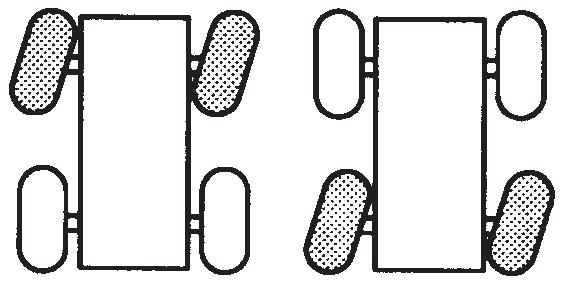
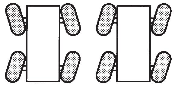
Steering
Steering is accomplished by the steering wheel and the rear steer control. These controls, used singly or together, provide front wheel steering, rear wheel steering, four-wheel steering, and crabbing capabilities (Figure3-16).
Front Wheel Steering
Conventional front wheel steering is accomplished with the steering wheel. This method of steering should always be used when traveling at higher speeds.
Warning
Unintentional Operation Hazard!
Operate the rear steer ONLY at slow speeds for added job site maneuverability.
Rear Wheel Steering
Rear wheel steering is controlled by the Rear Steer Control Switch. Moving the control switch to the desired position activates the rear steer cylinders, thereby steering the crane in the selected direction.
Four Wheel Steering
Four wheel steering is accomplished with the steering wheel and the Rear Steer Control Switch. Depending upon which direction the operator wishes to travel, the steering wheel is turned opposite direction of the Rear Steer control position. This allows the crane to turn or maneuver in close, restricted areas.
Crabbing
Crabbing is accomplished with the steering wheel and the Rear Steer Control Switch. Depending upon which direction the operator wishes to travel (crab), the steering wheel is turned in the same direction as the Rear Steer Control Switch. This permits driving the crane forward or backward in a crabbing manner.
3. Position the Drive Axle Selector Switch to four-wheel low.
NOTE: If the Drive Axle Selector Switch is positioned to four-wheel low and the Service Brake Foot Pedal is not depressed or the Transmission Shift Lever is not in neutral (N) position, the Four-Wheel Drive Indicator will flash and the four-wheel drive function will not engage.
4. Select gear speed and direction of travel using the Transmission Shift Lever and Knob.
5. Drive the crane as described under Traveling — Forward, page 3-31.
6. Return the Drive Axle Selector Switch to the two-wheel high position as soon as two-wheel traction will suffice and crane motion has stopped; again, the Service Brake Foot Pedal must be depressed and the Transmission Shift Lever must be in the neutral (N) position to shift from four-wheel low to two-wheel high.
Differential Lock Operation (Optional)
Caution
Unintended Operation!
Four-Wheel Drive Operation
CAUTION
Machine Damage Hazard!
Do not tow or pull in 1st gear with the Drive Axle Selector Switch in two-wheel drive position. Severe damage to the drive train will result. Always engage four-wheel drive.
If more traction is required due to slipping or spinning wheels, engage the front axle drive as follows:
Caution
Possible Machine Damage!
Before shifting from two-wheel drive to four-wheel drive (or from four back to two), crane travel must be stopped.
1. Stop the crane by depressing the Service Brake Foot Pedal.
2. Position the Transmission Shift Lever to the neutral (N) position.
When using the differential lock, steering characteristics may be affected.
Try to use four-wheel drive to gain adequate traction before using the differential lock.
Do not operate the differential lock when traveling downhill; at speeds above 10mph; on hard, dry surfaces; and/or during axle spin-out.
NOTE: The differential lock will not operate unless the Drive Selector Switch is in the four-wheel low position.
General
The purpose of the differential lock is to provide maximum traction and control on poor road or highway surfaces. When the differential locks are actuated, the clutch collar completely locks the differential case, gearing, and axle shafts together, thus maximizing traction to both wheels of each axle. The lock position will also protect against spinout. When normal driving conditions exist (during periods of good traction), the differential locks should not be actuated. The axles should be allowed to operate with differential action between both wheels.
Follow the steps below when engaging/disengaging the differential lock function.
1. Lock the differentials by pressing and holding the Axle Differential Control Switch in the lock position; disengage the function by releasing the switch.
2. Lock/unlock the differentials only when the vehicle is standing still or moving at a constant low speed with the wheels not slipping.
Caution
Possible Machine Damage!
When driving on hard, dry surfaces with the differentials locked, do not turn the wheels. Damage to the drive line components can result.
Do not lock the differentials when the wheels are slipping. Damage to the differentials can result.
3. Locked differentials cause the crane’s turning radius to increase, creating an understeer condition; use caution, good judgement and drive at low speeds when operating the vehicle with lock differentials.
4. Lock the differentials only when maximum traction is needed on poor road or highway surfaces.
Caution
Possible Loss of Vehicle Stability!
Do not lock the differentials when the vehicle is traveling down steep grades and traction is minimal.
5. Always unlock the differentials when the need for maximum traction has passed or when traveling on good road or highway surfaces.
Operation
The differential lock function should preferably be engaged when the crane is stationary but may be engaged when moving, if the following conditions are met:
1. The crane is moving very slowly (creep speed).
2. The wheels are not spinning at the time of engagement. When traveling with the differentials locked, do not deviate from a straight path more than is absolutely necessary. Engage the differential locks by doing the following:
1. Position the Axle Differential lock Control Switch to the locked position with the crane stationary or moving at a slow speed.
If moving at a slow speed, let up momentarily on the Foot Throttle Pedal to relieve torque on the differential gearing. This will fully engage the differential locks.
NOTE: When the differentials are locked, the Axle Differential Locked Indicator illuminates.
2. Proceed over the poor road condition cautiously. When the adverse condition has passed, disengage the differential locks by doing the following:
1. Release the Axle Differential Lock control Switch, allowing it to return to the unlocked position while maintaining a slow speed.
2. Let up momentarily on the Foot Throttle Pedal to relieve torque on the differential gearing, allowing the differential to fully unlock.
NOTE: When the differentials are unlocked, the Axle Differential Locked Indicator will not be illuminated.
3. Resume driving at a normal speed using good driving judgement.
Axle Oscillation Lockouts Operation
The following procedure should be used to periodically check the axle oscillation system and ensure that it is in proper working condition.
1. Ensure the tires are inflated to the recommended pressure. Refer to the Load Chart Book in the crane cab for proper inflation pressures.
2. With the hook unloaded, the boom fully retracted and centered over the front at no more than a 10° to 15° boom angle, position the crane on a block or curb so that one rear tire is approximately 6 to 12in (15 to 30cm) above the level of the opposite tire.
3. Slowly swing the superstructure to the left or right until the axle oscillation lockout valve is activated. This will lock the rear axle out of level. Do not swing beyond the tire track.
4. After engaging the swing brake, slowly drive off of the block or curb and stop. The rear tires should both be touching the road surface and the opposite front tire should be light or slightly off the road surface.
5. Release the swing brake and swing the superstructure until it is centered over the front
Warning
Tipping Hazard!
Do not operate the crane if the axle oscillation lockout system is not functioning properly.
Failure to comply with this warning may result in death or serious injury.
If the axle oscillation lockout valve is functioning properly, the crane will re-level itself; if the valve is not working properly, the crane will not re-level itself. If the rear axle does not lock or unlock properly, evaluate the lockout system and repair as necessary.
General Crane Operation Pump Drive
The main hydraulic pumps are mounted on the torque converter drive pad. The pumps operate any time the engine is running.
Control Lever Operation
The control lever operation for all crane functions is standard, i.e. the closer the lever is to neutral (center), the slower the system responds. The control lever should be returned to neutral to hold the load. Never feather the hoist control lever to hold the load.
NOTE: Always operate the control levers with slow, even pressure.
Preload Check
After the crane has been readied for service, an operational check of all crane functions (with no load applied) should be performed. The Preload Check is as follows:
NOTE: Operate engine at or near governed rpm during preload check of crane functions.
Carefully read and become familiar with all crane operating instructions before attempting a preload check or operating the crane under load.
1. Extend and set outriggers.
2. Raise, lower, and swing the boom a minimum of 45° right and left.
3. Telescope the boom in and out.
4. Raise and lower the cable a few times at various boom lengths. Ensure there is no kinking.
Using Your Load Chart
NOTE: One of the most important tools of every crane is the Load Chart found in the crane operator cab.
The Load Chart contains a large amount of information, which must be thoroughly understood by the operator.
The Load Chart contains outrigger capacity charts for fully extended, mid extended outriggers for the main boom and boom extension, and fully retracted outrigger beams for main boom only. In addition, the Load Chart contains two onrubber capacity charts: 360° stationary, and pick and carry over front.
The Load Charts are divided into structural strength and stability limits. This is shown by the bold line across the chart. Capacities above the line are structural strength limits and capacities below the line are stability limits.
The left column is the load radius, which is the distance from the center of crane rotation to the load center of gravity. The top row lists various boom lengths ranging from fully retracted to fully extended or boom extension lengths and offsets. The number at the intersection of the left column and top row is the total load capacity for that load radius and boom length or boom extension lengths offset. The number in parentheses below the total load capacity is the required boom angle (in degrees) for that load. When the boom length or lift radius or both are between values listed, the smallest load shown at either the next larger radius or next longer or shorter boom length shall be used.
Another important section is the range diagram. The range diagram shows the operating radius and tip height that can be achieved at a given boom length and angle. If the operator knows the radius and tip height required for a specific lift, the angle and boom length can be quickly determined from the range diagram. Or, if the boom length and angle are known, the tip height and operating radius can be quickly determined.
A lifting diagram is included to describe over side, over rear, and over front lifting areas. The lifting area diagram shows that the locations of the outrigger jack cylinders in the fully extended position are used to mark the boundaries of the lifting areas.
A boom extension capacity chart and notes are included to list the capacities for the extension length, load radius, and boom angle.
Another section contains the notes for lifting capacities. Be sure to read and understand all the notes concerning lifting capacities.
The load chart also gives weight reductions for load handling devices such as hook blocks, headache balls, boom extensions, etc., which must be taken into consideration as part of the load. Remember, the weight of any other load handling devices such as chains, slings, or spreader bars must be added to the weight of the load.
Proper Leveling of the Crane
ASME B30.5 specifies that if a crane is not level within 1% of grade, the allowable capacities must be reduced. Therefore, whether lifting on rubber or outriggers, it is essential that the crane is level to within 1% of grade. The bubble level that is provided on the crane is calibrated to be accurate within 1% of grade.
To properly level the crane, the boom must be positioned over the front of the crane, fully lowered to horizontal and fully retracted (for cranes fitted with a boom rest, the boom shall be stowed onto the rest). Raise and level the crane using the outriggers; refer to Setting the Outriggers, page 335.
A working crane may settle during lifting operations. Frequently check the crane for level. When rechecking the crane for level, the boom must be positioned over the front of the crane, fully lowered to horizontal and fully retracted (for cranes fitted with a boom rest, the boom shall be stowed onto the rest). If necessary, relevel the crane using the procedures under Setting the Outriggers, page 3-35.
Bubble Level Adjustment
The bubble level adjustment should be checked periodically; if it is suspected that the bubble level indicator is out of adjustment, verify and adjust the bubble level as follows:
1. Position the crane on a firm, level surface.
2. Extend and set the outriggers. Level the crane, as indicated by the bubble level indicator, using the outriggers.
3. Place a miracle pointer level, carpenter level, or similar type device on a machined surface such as the turntable bearing or bearing mounting surfaces.
4. Using the outriggers, level the crane as indicated on the leveling device used in step 3.
5. Using the bubble level indicator mounting screws, adjust the bubble level indicator to show level.
Crane Functions Setting the Outriggers
1. Engage the Parking Brake.
NOTE: The Parking Brake must be engaged to enable outrigger functions.
2. Position the outrigger floats directly out from each outrigger to where the outriggers will be properly extended.
Caution
Possible Equipment Damage!
Always depress one of the Outrigger/selector Switches before positioning the Outrigger Extension/retraction Switch to extend or retract. Failure to do this may cause a hydraulic lock against the individual solenoid valves, preventing them from opening.
Warning
Electrocution Hazard!
To avoid death or serious injury, keep all parts of this machine, the rigging, and materials being lifted at least 20 feet away from electrical power lines and equipment.
3. If extending the outrigger to the mid-extend or fully extended position, depress the desired Extension Switch on the Outrigger Selector Panel and hold the Outrigger Extension/Retraction Switch to EXTEND. The appropriate outrigger beam begins to extend. Refer to Engaging the Mid-Extend Lock Pin, page 3-36, if the crane is to be operated with any outrigger at the midextend position.
WARNING
Tipping Hazard!
All four outrigger beams must be deployed to one of three positions before beginning operation, which include fully retracted, mid-extend, or fully extended; do not operate the crane with the outriggers in any other position.
NOTE: More than one outrigger beam can be extended at a time. However, to ensure that each outrigger is fully extended, repeat step 3 for each outrigger after a multi-outrigger extension.
4. After deploying the four outrigger beams to one of the three proper positions (fully retracted, mid-extend, fully extended), depress the desired Jack Switch on the
Outrigger Selector Panel and hold the Outrigger Extension/Retraction Switch to EXTEND. The appropriate jack begins to move.
Extend each jack, positioning the float as necessary, until the locking levers of the float engage the jack cylinder barrel.
NOTE: More than one jack can be extended at a time.
5. Extend the front jacks approximately 3 to 4in (8 to 10cm).
6. Extend the rear jacks approximately 3 to 4in (8 to 10cm).
NOTE: If crane is equipped with tilting cab, ensure cab is in the lowered position before leveling machine.
7. Repeat step 4 until all wheels are clear of the ground and the crane is level as indicated by the bubble level indicator located on the right side of the cab.
NOTE: If it is suspected that the bubble level indicator is out of adjustment, verify and adjust the bubble level using the procedures under Bubble Level Adjustment, page 3-35.
Warning
Tipping Hazard!
The mid-extend outrigger beam lock pin must be engaged before operating on any beam from the mid-extend position.
The proper load chart and RCL program must be selected for the current outrigger configuration.
Outrigger Monitoring System (OMS) (Optional— Standard in North America)
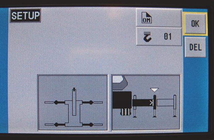
The Outrigger Monitoring System (OMS) aids the operator in accurately programming the Rated Capacity Limiter (RCL) by automatically identifying the horizontal position of each outrigger beam. The OMS uses four sensors, one per outrigger beam, to indicate when an outrigger beam is positioned to one of three pre-defined locations, including fully retracted, mid-extend, and fully extended.
Set up of the outriggers is the same for cranes equipped with OMS; refer to “Setting the Outriggers” on page35.
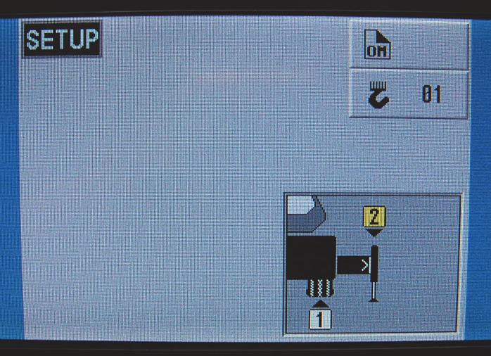
If the crane is setup on outriggers and “On Outriggers” is chosen when programming the RCL (Figure3-18), then the OMS indicates to the RCL the horizontal position of each of the four outrigger beams. Based on this information, the RCL will default to the most conservative outrigger beam configuration; that is, if three outriggers are fully extended and one is retracted, the RCL will select retracted as the outrigger configuration. A confirmation of this outrigger configuration is all that is needed (Figure3-19). Refer to the Rated Capacity Limiter Operator Handbook for detailed instructions.
NOTE: Figure3-19 depicts all four outrigger beams in the mid-extend position as indicated by the OMS and RCL.
Engaging the Mid-Extend Lock Pin
1. Turn the locking pin 90° from its stowed position and allow the pin to rest on top of the outrigger beam.
NOTE: It may be necessary to jog the outrigger extension/ retraction switch slightly to ensure proper pin engagement.
2. Slowly extend or retract the outrigger beam, allowing the locking pin to drop into the hole in the top of the outrigger beam, engaging the outrigger beam at the desired length.
Stowing the Outriggers
1. Select the rear jacks with the Jack Selector switches and hold the Extension/Retraction switch to RETRACT until the rear jacks have retracted several inches.
2. Select the front jack with the Jack Selector switches and hold the Extension/Retraction switch to RETRACT until the front jacks have retracted several inches.
3. Repeat steps 1 and 2 until the crane is resting on all four wheels and the jack floats are several inches off the ground
Caution
Crushing Hazard!
Keep feet and hands clear of floats when unlocking the floats from the jacks.
NOTE: Jack floats weigh approximately 99 lb (45 kg).
4. Release the locking levers and allow the floats to drop to the ground.
5. Continue to retract the jacks until they are fully retracted.
6. Depress the desired Extension rocker switch on the Outrigger Selector panel and hold the outrigger Extension/Retraction rocker switch to RETRACT. The appropriate outrigger beam should begin to retract.
NOTE: More than one outrigger may be retracted at one time.
7. After all outriggers have been fully retracted, stow the outrigger floats.
Stowing the Mid-Extend Lock Pin
1. Retract the outrigger extension/retraction cylinder.
NOTE: If the lock pin is wedged in the hole in the outrigger beam, it may be necessary to jog the outrigger extension/retraction switch slightly while pulling upward on the pin.
2. Lift the lock pin and turn it 90° to its stowed position.
Swinging the Boom
Warning
Crushing Hazard!
Death or serious injury could result from being crushed by moving machinery. Before activating swing, sound the horn and verify that all personnel are clear of rotating and moving parts.
Keep the area beneath the boom clear of all obstructions and personnel when lowering the boom.
The operator must select the proper load chart and RCL program for the outrigger position selected.
Caution
Machine Damage!
Never push or pull the swing control lever through neutral to the opposite direction to stop swing motion. Use the swing brake foot pedal to stop swing rotation.
NOTE: Automatic rear axle oscillation lockout will activate when the boom swings right or left of the crane centerline.
To swing the boom, the SWING control lever is pushed forward, away from the operator, to swing CLOCKWISE, or pulled back, toward the operator, to swing COUNTERCLOCKWISE. Always operate the control lever with a slow, even pressure. Use the swing brake foot pedal to stop rotation, then position the swing brake switch to ON to prevent further rotation.
Elevating the Boom
Warning
Crushing Hazard!
Keep the area above and below the boom clear of all obstructions and personnel when elevating the boom.
To elevate the boom, pull the BOOM (lift) control lever back, toward the operator, and hold until the boom reaches the desired elevation level.
Lowering the Boom
Warning
Crushing and/or Tipping Hazard!
Keep the area beneath the boom clear of all obstructions and personnel when lowering the boom. Long cantilever booms can create a tipping condition, even when unloaded and in an extended, lowered position.
Caution
Machine Damage!
When lowering the boom, simultaneously let out the hoist cable to prevent two-blocking the boom nose and hook block.
The closer the load is carried to the boom nose, the more important it becomes to simultaneously let out the hoist cable as the boom is lowered.
To lower the boom, push the Boom Control Lever forward, away from the operator, and hold until the boom is lowered to the desired position.
Extending the Boom
WARNING
Crushing Hazard!
Check the load chart for the maximum load at a given radius, boom angle, and length before extending the boom with a load.
Caution
Machine Damage!
Before extending the boom, ensure the large access cover on top of the boom base section is installed. When extending the boom, simultaneously let out the hoist cable to prevent two-blocking the boom nose and hook block.
NOTE: The telescope function is controlled by a foot pedal if the crane is equipped with an auxiliary hoist.
To extend the boom, push on the top of the Telescope Control foot pedal.
Retracting the Boom
Warning
Crushing Hazard!
When retracting the boom, the load will lower unless the hoist cable is taken in at the same time
To retract the boom, push on the bottom of the Telescope Control Foot Pedal.
Lowering and Raising the Hoist Cable
WARNING
Crushing Hazard!
Keep the area beneath the load clear of all obstructions and personnel when lowering or raising the cable (load). Do not jerk the control lever when starting or stopping the hoist. Jerking the lever causes the load to bounce, which could result in possible damage to the crane.
NOTE: When the load is stopped at the desired height, the automatic brake will engage and hold the load as long as the control lever remains in neutral.
Lowering the Cable
Push the Main or Aux hoist control lever forward, away from the operator, and hold until the hook or load is lowered to the desired height.
Raising the Cable
Pull the Main or Aux hoist control lever back, toward the operator, and hold until the hook or load is raised to the desired height.
Hoist Speed Range Selection
Caution
Equipment Damage!
Do not change the hoist speed range with the hoist in operation.
To change the speed range of the hoist(s), position the applicable switch (Main Hoist Speed or optional Aux Hoist Speed) to HIGH or LOW as applicable
Raising and Lowering the Hydraulic Boom Extension
The normal operating range for lifting loads with the hydraulic boom extension is an extension offset of 5 - 40 degrees. The extension must be retracted to 0 degree offset for stowage on the side of the boom.
The hydraulic luffing boom extension is controlled by two switches in the seat on the left hand seat armrest. The extension is controlled by an On/Off switch and a Raise/ Lower switch. See Luffing Jib Raise/Lower Switch (Optional) , page 3-15 for location and description of these switches.
The boom extension may also be controlled by two remote stations on the extension. The station is located on the boom extension adapter section, while the second station is located at the head of the boom extension base section.
Raising the Hydraulic Boom Extension
The Luffing Jib On/Off Switch must be in the ON position. Push the Luffing Jib Raise/Lower Switch to the RAISE position and hold until the extension is raised to the desired position or a switch-off point is reached.
To raise the extension to 0 degree offset for extension stowage, the Rated Capacity Limiter (RCL) system must be overridden. See the manufacturer’s RCL Operating Manual supplied with the crane for instructions.
To raise the extension at the remote stations, press the switch at the extension adapter or the switch at the head of the base section ((Figure3-20)).
Lowering the Hydraulic Boom Extension
WARNING Machine Damage!
When lowering the boom extension, simultaneously let out the hoist cable to prevent two-blocking the extension sheave and the hook block or headache ball.
The Luffing Jib On/Off Switch must be in the ON position. Push the Luffing Jib Raise/Lower Switch to the LOWER position and hold until the extension is lowered to the desired position or a switch-off point is reached.
To lower the extension at the remote stations, press the switch at the extension adapter or the switch at the head of the base section.
Operational Aids
Warning
Unexpected Operation Hazard!
Electronic equipment on this crane is intended as an aid to the operator. Under no condition should it be relied upon to replace the use of capacity charts and operating instructions. Sole reliance upon these electronic aids in place of good operating practices can cause an accident.
Rated Capacity Limiter (RCL) System
The Rated Capacity Limiter (RCL) is an electro-mechanical sensing system designed to alert the crane operator of impending capacity when the system has been properly preset by the operator. The control panel is mounted in the front console of the operator cab. When an overload condition is sensed, the system provides the operator with a visual and audible warning, and locks out the control levers to prevent lowering the boom, extending the boom, or raising the main or auxiliary hoist cables.
Three additional features are included within the RCL system:
• Swing Angle Set Limitation
• Work Area Definition
• Anti-two Block Device
Swing Angle Set Limitation allows left and right swing angle to be preset. When the preset angle is reached, the system will provide an audible warning.
Work Area Definition allows the crane operator to describe the crane’s working area by setting up “virtual walls”. They are referred to as virtual walls because they exist in the system and are not real walls. The virtual walls represent obstacles (i.e. buildings, towers, poles, etc.) in the crane’s working range. They are set by defining points along the outer limits of the working area with the tip of the boom. Once the working area has been defined, the system will provide a visual and an audible warning if the boom approaches a virtual wall.
Caution
Possible Machine Damage!
When defining virtual wall(s), always allow a safe working distance to any obstacles. Never work outside a safe working area as defined by common practice, standards, and manuals.
Warning
Risk of Unexpected Operation!
There are no cutouts associated with the swing angle set limitation or the work area definition features.
An Anti-Two Block Device is also incorporated into the system to prevent the hook block or headache ball from coming into contact with the boom nose or boom extension. This condition will also cause a lockout of hoist up, boom down, and telescope out, and also provide a visual and an audible alarm.
Refer to the RCL Operator Handbook for more detailed information on the function of the RCL system.
Control Lever Lockout System
The control lever lockout system consists of hydraulic solenoid valves (located in the directional control valves) which are in series between the hydraulic remote control valves in the cab and the pilot-operated directional control valves. When the valves are actuated, they prevent pilot flow between the hydraulic remote control valve in the cab and the appropriate directional control valve. The valves are activated in such a manner as to prevent worsening the condition, i.e. boom down, telescope out, or hoist up. The control lever lockout system is used with the anti-two-block system or the Rated Capacity Limiter (RCL) system.
Stowing and Parking
WARNING
Tipping Hazard!
Never park the crane near holes, or on rocky or extremely soft surfaces. This may cause the crane to overturn, resulting in injury to personnel.
When parking the crane, do the following:
1. Park the crane on a stable surface.
2. Remove the load from the hook.
3. Stow the swingaway boom extension, if erected.
4. Fully retract the boom and position it in the normal travel position.
5. Engage the swing brake and/or swing lock pin.
6. Retract all jack cylinders and outrigger beams.
7. Apply the parking brake.
Rt800e Operator Manual Operating Controls And Procedures
8. Put all operating controls in the neutral position.
9. Position the Crane Function switch to OFF.
10. Shut down the engine following the proper procedures specified in this Handbook and the applicable Engine manual.
11. Remove the keys.
12. Close and lock all windows, covers, and doors.
Caution
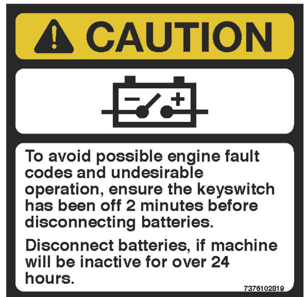
Risk of Undesirable Operation!
To avoid possible engine fault codes and undesirable operation, ensure the keyswitch has been off two minutes before disconnecting the batteries. Disconnect batteries, if machine will be inactive for over 24 hours.
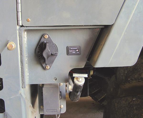
13. Turn Battery Disconnect to OFF position (shown) if machine will be inactive for over 24 hours (Figure3-21).
Warning
Tipping Hazard!
Changing weather conditions including but not limited to: wind, ice accumulation, precipitation, flooding, lightning, etc. should be considered when determining the location and configuration of a crane when it is to be left unattended.
Failure to comply with these instructions may cause death or serious injury.
The configuration in which the crane should be left while unattended shall be determined by a qualified, designated individual familiar with the job site, configuration, conditions, and limitations.
General
This section provides procedures for installing the hoist cable on the hoist drum, cable reeving, and erecting and stowing the boom extension.
Installing Cable On The Hoist
Caution
If cable is wound from the storage drum, the reel should be rotated in the same direction as the hoist.
NOTE: The cable should preferably be straightened before installation on the hoist drum.
Install cable on the hoist drum in accordance with the following procedure.
1. Position the cable over the boom nose sheave and route to the hoist drum.
2. Position the hoist drum with the cable anchor slot on top.
3. Insert the cable through the slot and position around the anchor wedge (1) (Figure4-1).
NOTE: The end of the cable should be even with the bottom of the slot for the anchor wedge.
4. Position the anchor wedge in the drum slot; pull firmly on the free end (2) of the cable to secure the wedge.
NOTE: If the wedge does not seat securely in the slot, carefully tap (3) the top of the wedge with a mallet.
Danger
Entanglement Hazard!
Death or serious injury may result if entanglement occurs during hoist operation.
Keep all body parts and loose clothing clear while hoist is operating.
5. Slowly rotate the drum, ensuring the first layer of cable is evenly wound onto the drum.
6. Install the remainder of the cable, as applicable.
Cable Reeving
NOTE: There are two types of cable (wire rope) available on this crane; 6 x 36 WS and 35 x 7 (non-rotating).
Within the limits of the load and range charts and permissible line pull, multi-part lines allow the operator to raise a greater load than can be raised with a single part line. Various cable reeving (part line) is possible with the boom nose and hook block Figure 4-7. This reeving should be performed by a qualified rigger using standard rigging procedures.
Caution
Do not reeve Auxiliary Hoist rope through the rope grab. Do reeve the Main Hoist rope through the rope grab. Figure 4-2
NOTE: Also use the rope grab when using the Main Hoist with lattice extensions responsible and should proceed in compliance with the regulations in force. If there are any questions, contact your local Manitowoc Distributor or Manitowoc Crane Care.
In order to quick reeve the hook block without removing the wedge socket on the end of the cable, see Figure 4-3.
Do not mix components from different manufacturers. The selection, installation and use of a wedge socket assembly must be in accordance with the requirements of the wedge socket manufacturer and the wire rope manufacturer upon whose wire rope the wedge socket assembly will be used.
Grove specifies the size, type, class and line pulls for wire rope, predominately rotation resistant wire rope, and rigging accessories such as overhaul balls and hook blocks for use with each new crane that it manufactures. Other wire ropes and rigging accessories are available from various vendors. Different wire rope manufacturers have differing requirements for the construction, handling, cutting, seizing, installation, termination, inspection and replacement of the wire ropes they produce. Their advice should be sought for each specific type of wire rope a crane user intends to install on a mobile crane.
When assembly is complete, raise the boom to a working position with a load suspended to firmly seat the wedge and rope into the socket before the crane is used operationally.
Caution
If the socket is not positioned with the flat face away from the boom sections, structural damage will occur.
When anchoring the socket to the boom, ensure the flat face of the socket is in position, as shown, away from the boom sections (Figure4-4).
Boom Cable Reeving
When reeving the boom, always reeve the main hoist wire rope through the rope grab; if also reeving the auxiliary hoist rope, reeve the auxiliary hoist rope outside of the rope grab.
DEAD-END RIGGING/WEDGE SOCKETS
Wedge socket assemblies are popular rigging accessories and have been successfully used for decades to terminate wire ropes on mobile cranes. A wedge socket assembly is easily installed and dismantled but it must be installed and used correctly. It is essential to use only a wedge and socket of the correct size for the rope fitted. Failure to do so may result in the rope pulling through the fitting.
Since state and local laws may vary, alternate attachment methods may be necessary depending upon work conditions. If alternate methods are selected, the user is
Wedge Socket Installation
1. Inspect the wedge and socket. Remove any rough edges and burrs.
2. The end of the wire rope should be seized using soft, or annealed wire or strand. If the end of the rope is welded, the welded end should be cut off. Do not weld on size 6X37 rope. This will allow the distortion of the rope strands, caused by the bend around the wedge, to adjust themselves at the end of the line. Refer to Section 1 - Introduction in the Service Manual for wire rope procedures. service. It is the wedge that secures the wire rope inside the socket. The dead-end treatment is used to restrain the wedge from becoming dislodged from the socket should the rope suddenly become unloaded due to the headache ball or hook block striking the ground, etc.
3. Make sure the live-end ((Figure4-5)) of the rope is directly in line with the ears of the socket and the direction of pull to which the rope will be subjected. If the rope is loaded into the socket incorrectly, under a load the rope will bend as it leaves the socket, and the edge of the socket will wear into the rope causing damage to the rope and eventual failure.
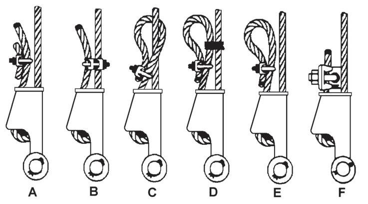
Sketches A through F ((Figure4-6)) illustrate various ANSI approved methods for treating the dead-ends of wire ropes which exit a wedge socket assembly. While use of the loopback method is acceptable, care must be exercised to avoid the loop becoming entangled with tree branches and other components during crane transport and with the anti-two block system and other components during use of the crane. Of the methods shown below, Manitowoc prefers that method A or F be used, i.e., clipping a short piece of wire rope to the dead-end or using a commercially available specialty clip or wedge. Typically, it is recommended that the tail length of the dead-end should be a minimum of 6 rope diameters but not less that 6in (15.2cm) for standard 6 to 8 strand ropes and 20 rope diameters but not less than 6in (15.2cm) for rotation resistant wire ropes.
When using method A, place a wire rope clip around the dead end by clamping a short extra piece of rope to the rope dead end. DO NOT CLAMP THE LIVE END. The U-bolt should bear against the dead end. The saddle of the clip should bear against the short extra piece. Torque the U-bolts according to the table titled Wire Rope Clip Torque Values ((Table 4-1)).
4. Insert the end of the wire rope into the socket, form a loop in the rope, and route the rope back through the socket allowing the dead-end ((Figure4-5)) to protrude from the socket. Ensure the dead-end of the rope is of sufficient length to apply end treatment to the dead-end after the wedge has been seated.
5. Insert the wedge into the loop and pull the live-end of the rope until the wedge and rope are snug inside the socket. It is recommended that the wedge be seated inside the socket to properly secure the wire rope by using the crane’s hoist to first apply a light load to the live-end.
6. After final pin connections are made, increase the loads gradually until the wedge is properly seated.
7. The wire rope and wedge must be properly secured inside the socket before placing the crane into lifting
NOTE: The use of swivels is not allowed in conjunction with non-rotation resistant wire ropes
Other sources for information with which crane users should be familiar and follow is provided by the American Society of Mechanical Engineers, American National Standard, ASME B30.5, latest revised. ASME (formerly ANSI) B30.5 applies to cableways, cranes, derricks, hoists, hooks, jacks, and slings. It states, in section 5-1.7.3, “(c) Swagged, compressed, or wedge socket fittings shall be applied as recommended by the rope, crane or fitting manufacture.” Wire ropes are addressed in ASME B30.5, section 5-1.7.2, ROPES, it states, in pertinent part, “(a) The ropes shall be of a construction recommended by the rope or crane manufacturer, or person qualified for that service.” Additional information is published by the Wire Rope Technical Board in the Wire Rope Users Manual, latest revised edition.
HOOK BLOCK DEAD END
BOTTOM BOOM NOSE SHEAVES
TO MAIN HOIST
UPPER BOOM NOSE SHEAVE
HOOK BLOCK SHEAVES
AUXILIARY NOSE
TO MAIN HOIST
BOTTOM BOOM NOSE SHEAVES
UPPER BOOM NOSE SHEAVE
BOOM NOSE DEAD END
HOOK BLOCK SHEAVES
FIGURE4-7
Published 04-05-2017 Control # 307-08
Counterweight and Auxiliary Hoist Removal
1. Position the crane on a firm, level surface. Fully extend and set the outriggers. Level the crane.
2. Position the boom over the front of the machine and engage the turntable lock.
3. Remove any load and handling device from the auxiliary hoist cable and retract all cable onto the hoist drum. Secure the cable.
4. Disconnect the auxiliary hoist hydraulic lines and electrical harness and secure. Do not disconnect the counterweight removal cylinder hydraulic lines.
5. Remove the ball detent pins which secure the counterweight mounting pins.
6. Ensure that the counterweight removal cylinder support pins are securely attaching the counterweight to the turntable wing-support brackets. Disengage the counterweight mounting pins using the pinning control lever (center).
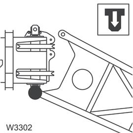
NOTE: It may be necessary to retract the counterweight removal cylinders (Figure4-9) and (Figure4-10) to relieve weight from the counterweight mounting pins.
7. Using the control levers (left and right), simultaneously extend (lower) the counterweight onto the frame counterweight supports. Feather individual controls as required to lower the counterweight in a level position.
8. Remove the counterweight removal support pins from turntable wing-support brackets and using the control levers (left and right), retract the counterweight removal cylinders fully.
9. Disconnect and secure the counterweight removal cylinder hydraulic lines and replace the counterweight removal cylinder support pins on the turntable wingsupport brackets.
10. Properly attach chains with clevis to the counterweight lifting holes (Figure4-9) and use a crane to carefully transfer the counterweight and auxiliary hoist to the ground or a suitable transport vehicle.
Installation
1. Position the crane on a firm, level surface. Fully extend and set the outriggers. Level the crane.
2. Position the boom over the front of the machine and engage the turntable lock.
3. Properly attach chains with clevis to the counterweight lifting holes (Figure4-9) and use a crane to carefully transfer the counterweight and auxiliary hoist to the frame counterweight supports over the rear outrigger box.
4. Attach the counterweight removal cylinder hydraulic lines.
5. Using the control levers (left and right), extend the counterweight removal cylinders, one at a time, guiding them into the turntable wing/support brackets and pin securely.
6. Using the control levers (left and right), simultaneously retract (raise) the counterweight removal cylinders until the counterweight round bar engages the lugs on the turntable and the counterweight pinning holes are aligned with the counterweight mounting pins. Feather individual controls as required to raise the counterweight in a level position.
7. Engage the counterweight mounting pins using the control lever (center).
8. Attach the ball detent pins securing the counterweight mounting pins.
9. Relieve pressure on the counterweight removal cylinder so that weight is fully supported by the counterweight mounting pins.
10. Attach the auxiliary hoist hydraulic lines and electrical harness.
Counterweight without Auxiliary Hoist Removal
1. Position the crane on a firm, level surface. Fully extend and set the outriggers.
2. Position the boom over the front of the machine and engage the turntable lock.
3. Remove the ball detent pins which secure the counterweight mounting pins.
4. Ensure that the counterweight removal cylinder support pins are securely attaching the counterweight to the turntable wing/support brackets. Disengage the counterweight mounting pins using the pinning control lever (center).
NOTE: It may be necessary to retract the counterweight removal cylinders to re lieve weight from the counterweight mounting pins.
5. Using the control levers (left and right), simultaneously extend (lower) the counterweight onto the frame counterweight supports. Feather individual controls as required to lower the counterweight in a level position.
6. Remove the counterweight removal cylinder support pins from turntable wing/support brackets and using the control levers (left and right), retract the counterweight removal cylinders fully.
7. Disconnect and secure the counterweight removal cylinder hydraulic lines and replace the counterweight removal cylinder support pins on the turntable wing/ support brackets.
8. If applicable, properly attach chains with clevis to the counterweight lifting holes (Figure4-9) and use a crane to carefully transfer the counterweight to the ground or a suitable transport vehicle.
Installation
1. Position the crane on a firm, level surface. Fully extend and set the outriggers. Level the crane.
2. Position the boom over the front of the machine and engage the turntable lock.
3. If applicable, properly attach chains with clevis to the counterweight lifting holes (Figure4-9) and use a crane to carefully transfer the counterweight to the frame counterweight supports over the rear outrigger box.
4. Attach the counterweight removal cylinder hydraulic lines.
5. Using the control levers (left and right) extend the counterweight removal cylinders, one at a time, guiding them into the turntable wing/support brackets and pin securely.
6. Using the control levers (left and right) simultaneously retract (raise) the counterweight removal cylinders until the counterweight round bar engages the lugs on the turntable and the counterweight pinning holes are aligned with the counterweight mounting pins. Feather individual controls as required to raise the counterweight in a level position.
7. Engage the counterweight mounting pins using the control lever (center).
8. Attach the ball detent pins securing the counterweight mounting pins.
9. Relieve pressure on the counterweight removal cylinder so that weight is fully supported by the counterweight mounting pins.
INSTALLING THE BI-FOLD MANUAL BOOM EXTENSION
Danger
To prevent serious injury or death, always wear personal protective equipment; i.e., a hard hat, eye protection, gloves and metatarsal boots.
1. Before installing the boom extension make sure the crane is set up on outriggers using normal setup procedures. Refer to Setting the Outriggers, page 3-35.
NOTE: An auxiliary crane with sling is required to install the bi-fold boom extension.
2. Check the transport condition of the bi-fold extension.
3. Using an auxiliary crane, attach sling to the bi-fold extension.
4. Lift the bi-fold extension in front of the main boom with the auxiliary crane and lock the 33 ft (10.1 m) section to the right of the main boom head (Figure4-11).
FIGURE4-11
5. Pin the left side to the boom nose.
6. Establish electrical connection between the extension and the main boom.
7. For units equipped with hydraulic luffing boom extension, establish hydraulic connections between the extension and the main boom.
NOTE: You can also install the bi-fold swingaway boom extension in front of a 16 ft (4.9 m) section when you are changing directly from the 56 ft (17.1 m) bifold swingaway extension to a boom extension.
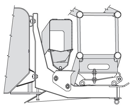
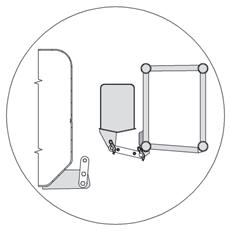
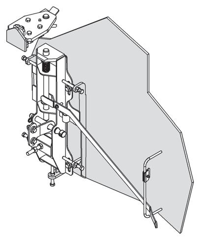
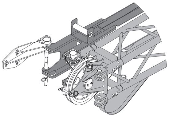
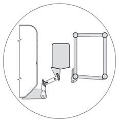
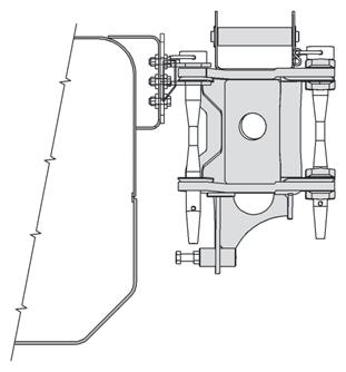
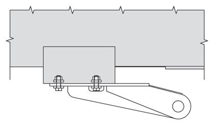
Checking the Transport Condition
For transportation you must establish certain connections between both parts of the lattice extension. The connections which need to be established depend on whether the lattice extension:
- is folded up at the side of the main boom for transportation or
- is completely removed for transportation.
Danger
Be careful not to damage the lattice extension and the main boom. Always put the lattice extension into transport condition when folded at the side or working with the main boom. Only then is the lattice extension secured against slipping. This way you prevent the partly fastened lattice extension hitting the main boom or the individual components of the lattice extension hitting each other and becoming damaged.
You must check transport condition:
- After stowing the lattice extension, before you drive the crane with the lattice extension folded at the side or work with the main boom.
- Before installation and before erecting the lattice extension.
The transport condition with the lattice extension folded at the side is created when all of the following connections are established.
• Check the connections and establish them if necessary (Figure4-12).
If 23 ft (7 m) section and 33 ft (10.1 m) section are folded at the side:
- The 33 ft (10.1 m) section is locked at the front support (1) on the main boom and is secured with a retaining pin (2)
- The pins (4) are inserted on the pivot point between the 23 ft (7 m) section and the 33 ft (10.1 m) section.
- The connection (7) in the middle area is between the 23 ft (7 m) section/33 ft (10.1 m) section.
- The connection (5) between 23 ft (7 m) section and main boom in the rear area is established (Figure4-12) (control # 6510-7).
If the 23 ft (7 m) section only is folded at the side:
- The connection (7) in the middle area is between the 23 ft (7 m) section and the main boom (3) (Figure4-12).
- The connection (5) between the 23 ft (7 m) section and the main boom in the rear area is established.
Boom Extension Erecting And Stowing Procedure
General Warnings
Warning
To prevent serious injury or death, always wear personal protective equipment; i.e., a hard hat, eye protection, gloves and metatarsal boots. Boom angles are used to control speed at which extensions swing during erecting and stowage. Improper boom angles will cause uncontrollable swing speeds of extension.
NOTE: Tag line used in these procedures is to control the movement of the boom extension.
Preparing the Crane for Boom Extension Erection Procedure
NOTE: The data in this section also applies to the erection of the boom extension.
Requirements for Boom Extension Erection
Before you erect a lattice extension or the boom extension, the following requirements must be met:
- The swingaway lattice extension is mounted on the side of the main boom and is in transport condition.
- The crane is supported by the outriggers according to the lifting capacity chart for the planned operation with the lattice extension and is aligned horizontally.
- The main boom is completely retracted and has been lowered into horizontal position.
- If the crane is equipped with two hoists with additional equipment, the hook block is unreeved on the hoist, which is not used for working with the lattice extension.
Requirements for Stowing the Boom Extension
Before you lower a lattice extension or the boom extension into a horizontal position, the following requirements must be met:
- No other load is raised apart from the hook block.
- The counterweight required according to the lifting capacity chart for the planned operation with the lattice extension is rigged.
- The crane is supported with the outriggers prescribed for operation with the erected lattice extension according to the lifting capacity chart
- The main boom is fully retracted.
Securing Lattice Extension With Tag Line (Rope)
Danger
Always secure the lattice extension with a tag line (rope) on the main boom before removing any connections. This will prevent the lattice extension from slipping off the runup rail, swinging around and knocking you off the carrier or injuring other persons in the swing range.
The lattice extension may swing out on its own accord when you remove the last connection that held the lattice extension at the side of the main boom.
You must therefore secure the lattice extension before you begin with the erection procedure.
Secure the lattice extension as follows:
• Attach a tag line (rope) at the front of the lattice extension.
• Guide the tag line (rope) underneath the lattice extension, via the holding rod on the main boom and back again.
• Have a helper hold the tag line (rope) tight while you are removing the last connection.
NOTE: If you are alone, secure the other end of the tag line (rope) on the crane (e.g. on the steps of the access ladder to the carrier or to the hole in the superstructure). Leave enough play in the tag line (rope) that it is tight only when you swing the lattice extension towards the main boom head later on. Refer to Erection and Stowing Procedure
Erecting Procedure
33 ft (10.1 m) Boom Extension
Danger
To prevent serious injury or death, do not stand on decking until extensions are secure.
1. Visually check to ensure all pins are installed.
2. Crane should be set up on outriggers using normal setup procedures (Figure4-13). Refer to Setting the Outriggers, page 3-35 a. Fully retract boom. b. Lower boom to horizontal for erecting over the front of the crane.
NOTE: Tag line is used to control movement of the boom extension during erecting procedure.
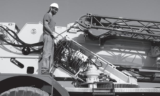
3. Attach tag line (1) (Figure4-14) to tip of extension.
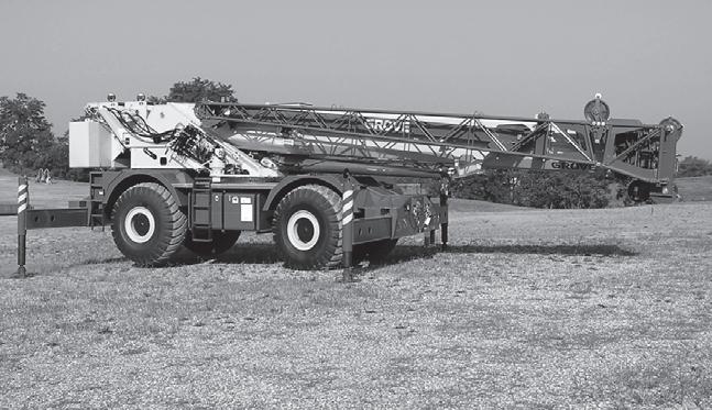
4. Pull the ramp latch pin (1) (Figure4-15).
5. Swing the stowage ramp out and latch into the folded out position (1) (Figure4-16).
7. If not using the bi-fold 23 ft (7 m) section, remove the retainer clip and bi-fold stowage pin (1) (Figure4-18) at the 33 ft lattice section connection. Stow pin on bi-fold. Leave the pin (2) attaching the 23 ft (7 m) section to the base section to retain the 23 ft (7 m) section.
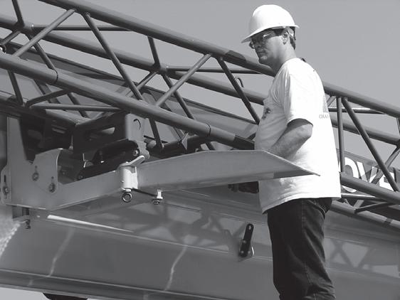
NOTE: If erecting the 33 ft (10.1 m) section without the 23 ft (7 m) section, perform steps 6 and 7, otherwise proceed to Step 10.
6. If not using the bi-fold 23 ft (7 m) section, remove pin (1) (Figure4-17), photo from the locking bar (2). Move locking bar (2) to the base section attachment bar (1) and install pin (3). Secure with retaining pin.
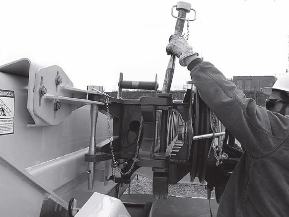
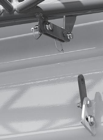
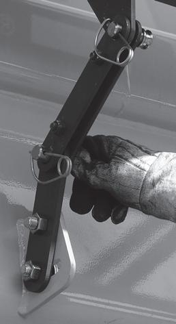
NOTE: Step 8., Step 9. and Step 10. apply when erecting the 23 ft (7 m) section together with the 33 ft (10.1 m)section. If not using the bi-fold 23 ft (7 m) section, proceed to Step 11..
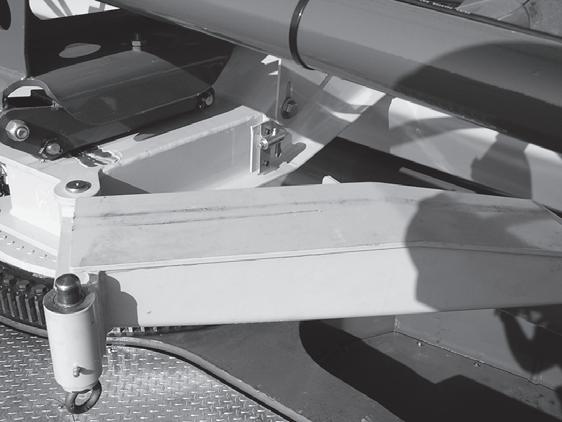
11. Using tag line, swing extension into position and align the lugs on the extension (1) (Figure4-22) with holes on the boom nose lugs (2).
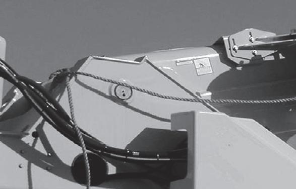
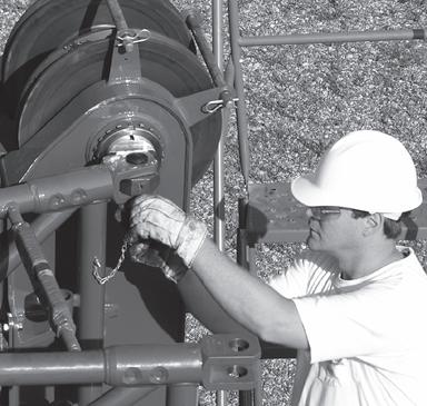
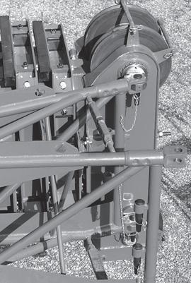
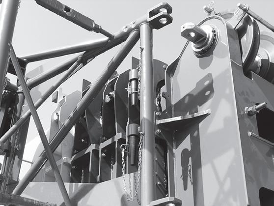
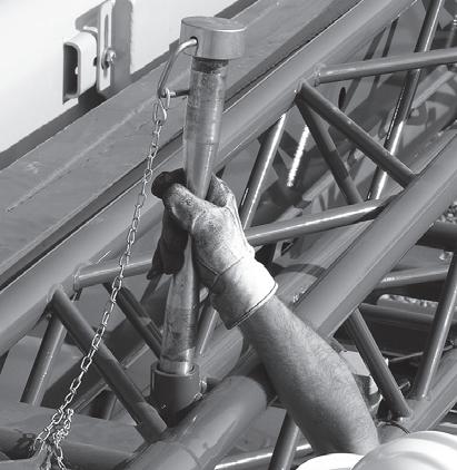
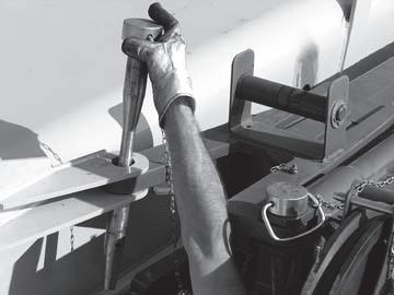
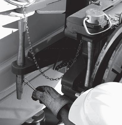
Published 04-05-2017 Control # 307-08
Danger
To prevent serious injury or death, do not stand or sit on the crane deck when pulling the boom extension off the stowage ramp.
Once the front latch pins are removed and the boom extension is free from the ramp it may abruptly swing with enough force to severely injury or cause death to anyone standing or sitting on the crane deck.
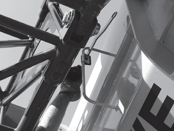
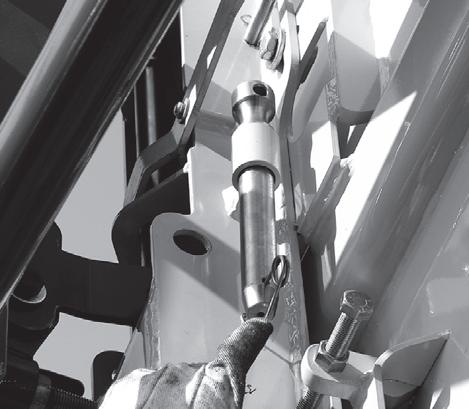
14. Remove horizontal locking pin (1) (Figure4-25) retainer clip.
DO NOT remove the locking pin (1) (Figure4-25) while standing on the crane deck. Remove the locking pin after moving off the crane deck and onto the ground.
Before moving to the ground, attach the jib extension pole (tool p/n 7714100000) located on the cab to the horizontal locking pin by placing the pole hooked end through the hole in the head of the locking pin (1), extend the pole so it will reach the ground.
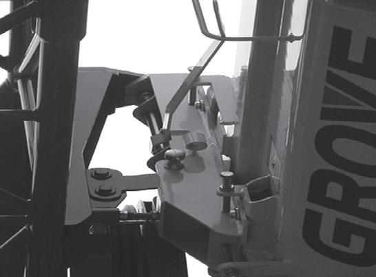
After moving to the ground, pull the locking pin (1) out of the front latching bracket using the jib extension pole.
16. Disengage front latch assembly by pushing handle (1) (Figure4-27) up and into the handle rest (2).
17. Remove tag line from superstructure.
NOTE: Tag line is used to control movement of the boom extension during erecting procedure.
NOTE: If erecting the 23 ft (7 m) section with the 33 ft (10.1 m)section, perform steps 18 and 19. If erecting the 33 ft (10.1 m) section without the 23 ft (7 m) section, proceed to Step 20.
18. Using the tag line (rope), pull the extension (1) (Figure4-28) off the ramp.
19. While maintaining control of the extension with the tag line, swing extension (1) (Figure4-28) into position on boom nose.
NOTE: Step 20 is with the 23 ft (7m) section (1) (Figure4-29) stowed on boom.
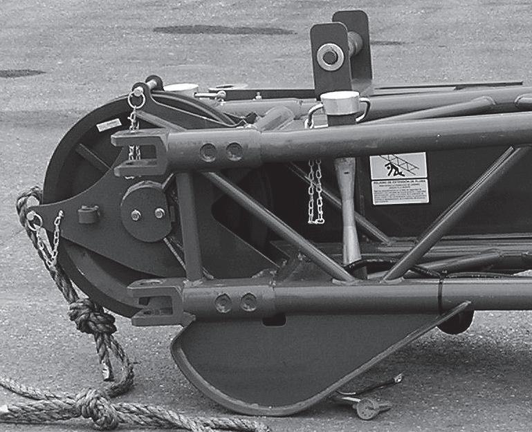
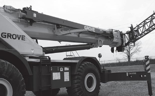
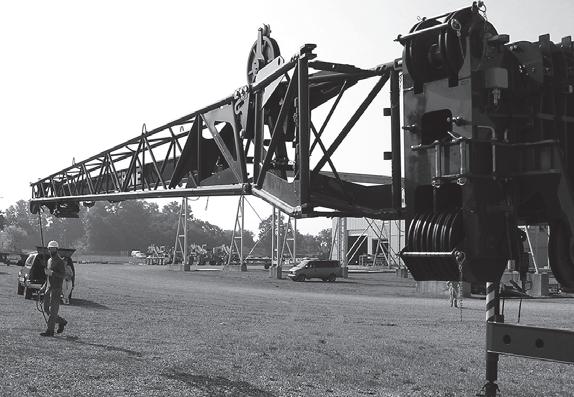
Relieving the Load on Bearing Points
NOTE: The dead weight of the lattice extension can cause the bearing points on the left side to be misaligned or the pins to get weighted which makes it impossible to knock them out.
When establishing or disconnecting the connections, proceed as follows:
• Lower the lattice extension until the supports are on the ground (1) (Figure4-31). If necessary, override the lifting limit switch.
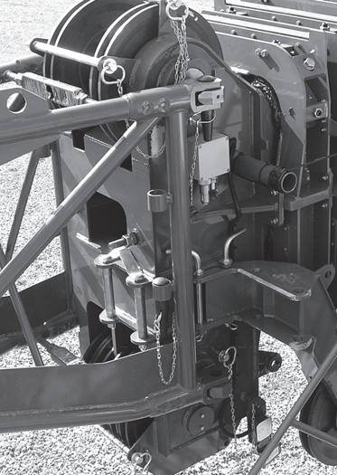
• Continue to lower carefully until the connecting points (1) (Figure4-32) align or until the load has been removed from the pins.
NOTE: If crane is equipped with a hydraulic luffing boom extension, connect the hydraulic couplings between the extension and main boom. Refer to Connecting and Disconnecting the Hydraulic Boom Extension in this section.
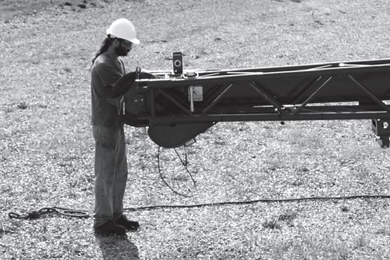
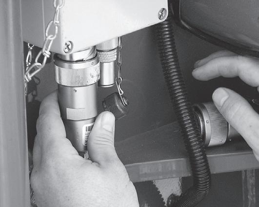
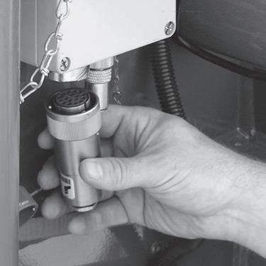
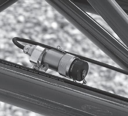
23. Lower boom and remove tag line (1) (Figure4-36) from the tip of the extension. (Figure4-36) shows the 23 ft (7m) and 33 ft (10.1 m) section together.
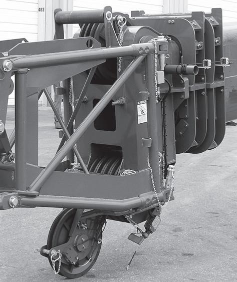
56 ft (17.1 m) Boom Extension
1. Secure tag line (1) (Figure4-37) to the bi-fold nose.
NOTE: Do not lower boom until bi-fold has been completely swung in front of the 33 ft (10.1 m) section.
5. Lower the boom.
6. Remove pin (1) (Figure4-40) from swingaway. Install pin in bi-fold and retain with clip pin.
2. Raise boom slightly above horizontal.
3. Remove retainer clip (2) (Figure4-38) and remove bifold stowage pin (1).
7. Connect RCL (1) (Figure4-41) connector to RCL connection box. The cable is stowed in the 23 ft (7m) section.
4. Using the tag line (1) (Figure4-39) to maintain control of the bi-fold (stinger), swing stinger into erected position.
8. Remove tag line before operating crane.
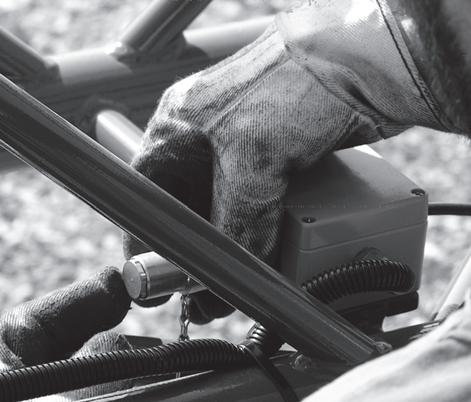
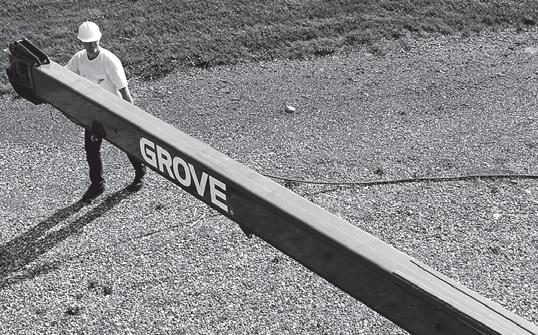

NOTE: Reeve the hoist cable as described under rigging and unrigging procedure in this section.
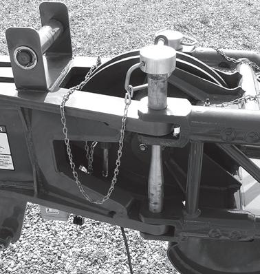
Published 04-05-2017 Control # 307-08
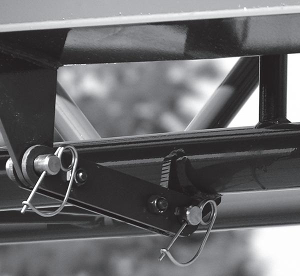
Stowing Procedure, Boom Extensions
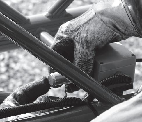
Stowing 23 ft (7 m) Bi-fold Extension
Danger
To prevent serious injury or death, do not stand on decking until extensions are secure.
1. Lower boom below horizontal.
2. Attach tag line (1) (Figure4-42) to bi-fold extension nose.
5. Raise boom to slightly above horizontal.
6. Using tag line to control movement of the bi-fold extension, swing it into stowed position on the main boom (Figure4-45).
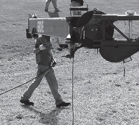
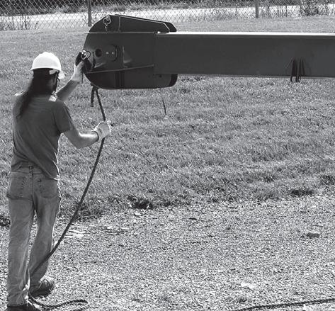
3. Disconnect RCL connection (1) (Figure4-43). Stow the cable in the 23 ft (7 m) section.
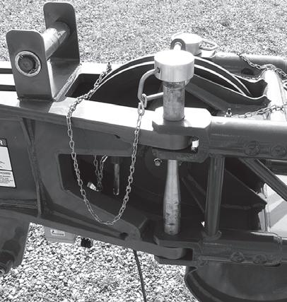
4. Remove retainer clip and remove the left side bi-fold retaining pin (1) (Figure4-44). Place pin in holder.
7. Raise boom slightly above horizontal.
8. Connect stowage link (1) (Figure4-46) to bi-fold and install pin (2) and retainer clip (3).
9. Remove tag line from bi-fold extension.
33 ft (10.1 m) Lattice Boom Extension
1. Lower boom and secure tag line (1) (Figure4-47) to tip of boom extension. Figure 4-47 shows the 23 ft (7 m) bifold and 33 ft (10.1) lattice extension together.
c. Route cable through boom extension and stow connector (1) (Figure4-50).
2. Disconnect RCL Cable.
a. Remove connector (1) (Figure4-48) from junction box on boom nose.
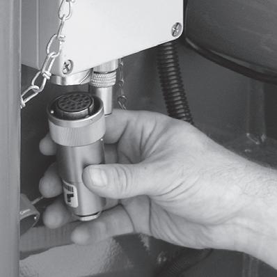
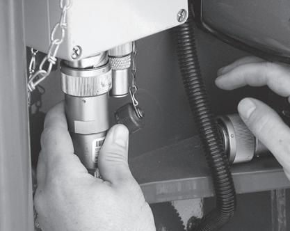
NOTE: If crane is equipped with a hydraulic luffing boom extension, disconnect the hydraulic couplings between the extension and main boom. Refer to Connecting and Disconnecting the Hydraulic Boom Extension in this section.
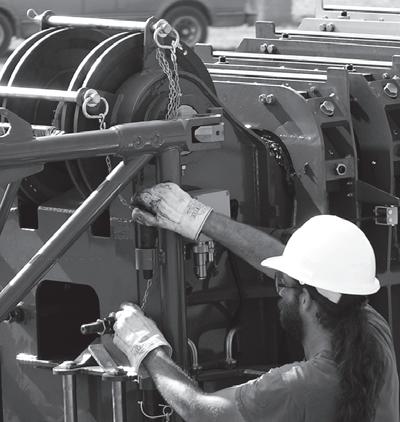
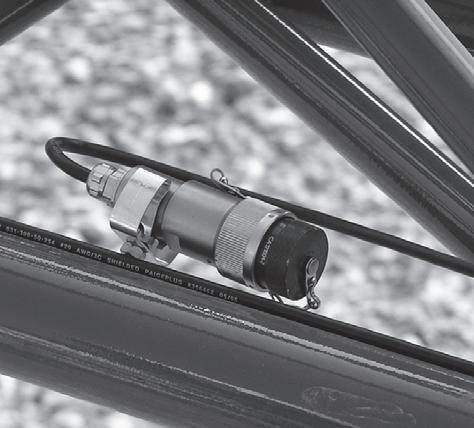
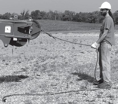
3. Remove retainer clips and remove pins (1) (Figure4-51) attaching the boom extension to the left side of boom nose. Stow the pins in the boom extension pin holders (2) (Figure4-51) and install the retainer clips.
b. Install dummy plug (1) (Figure4-49) on junction box.
4. Raise boom to horizontal.
5. Pull the front latch handle down (1) (Figure4-52).
7. Raise boom to slightly above horizontal.
NOTE: Step 8 is stowing with the 23 ft (7m) extension and 33 ft (10.1 m) section together. If the 23 ft (7m) section remained on the boom, proceed to step Step 9.
8. When stowing both the 33 ft lattice boom extension and the 23 ft bi-fold, use the tag line to maintain control of the boom extension, and swing the extension into the stowed position (Figure4-54), (Figure4-56), (Figure4-57).
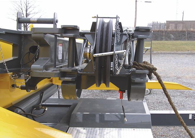
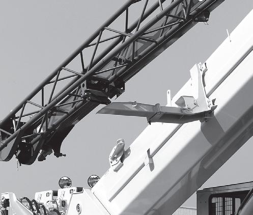
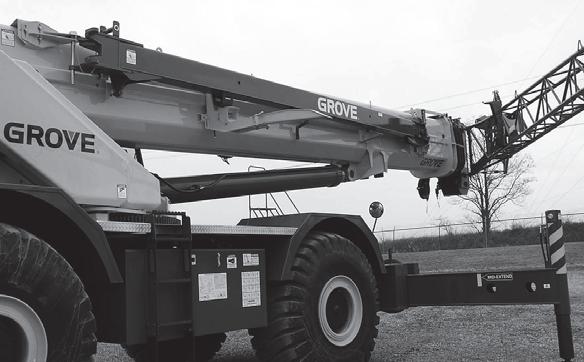
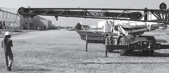
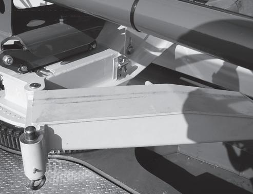
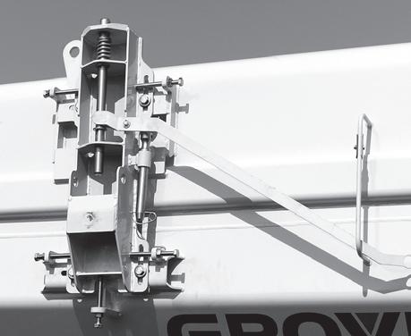
NOTE: Step 9. is with the 23 ft (7 m) section stowed on boom. If stowing the 23 ft (7 m) section and 33 ft (10.1 m) section together, proceed to step Step 10.
9. When stowing only the 33 ft. lattice boom extension. Use the tag line to maintain control of the boom extension, and swing the extension into the stowed position (Figure4-55), (Figure4-56), (Figure4-57).
10. Secure tag line (1) (Figure4-58) to hole in rear of superstructure while boom is still elevated.
Danger
If front latch spring pin (2) (Figure4-59) & (2) (Figure4-60) does not engage the 33 ft lattice extension (1) (Figure4-59), STOP. DO NOT continue to stow the boom extensions until the front latch spring pin (2) has been properly engaged and the locking pin (4) (Figure4-60) has also been installed correctly.
DO NOT climb onto decking or walk under boom extensions.
Sever injury or death may occur if the front latching mechanism is not properly attached to the boom extensions; the boom extensions may fall or swing away from the main boom stowage brackets.
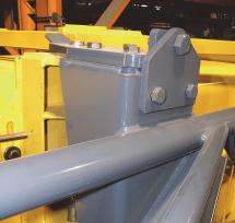
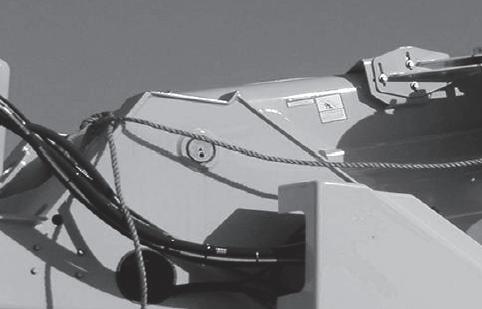
11. Raise boom until front latch spring pin 2, (Figure4-59) engages the 33 ft lattice extension. Verify that the spring pin handle (not shown, see Figure 4-52) is in the down position and against stop bar.
Contact Manitowoc Crane Care for correct adjustments if unable to align the lattice extension with the spring pin (2) (Figure4-59) & (2) (Figure4-60)or the locking pin (4) (Figure4-60).
12. Before proceeding with stowing boom extensions; verify that the spring pin (2) (Figure4-59) has engaged the lattice extension (1) as shown in (Figure4-59). The end of the spring pin (2) must be through and beyond the end of the hole in the bracket.
From ground leve l, visually verify spring pin (2) (Figure4-60) has engaged the 33 ft lattice extension (5). Check for engagement by seeing if spring (1) is extended; washer (3) should not be touching plate.
WARNING
Do not lower boom if stowage latch is not engaged.
Danger
Never remove the stowage pins (1, Figure 4-61) from the right side boom nose lugs until the 33 ft (10.1 m) lattice extension has been properly placed on the rear stowage ramp and secured to the front latching bracket (Figure 4-59 and Figure 4-60).
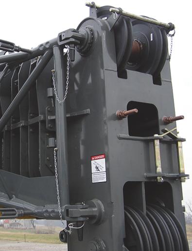
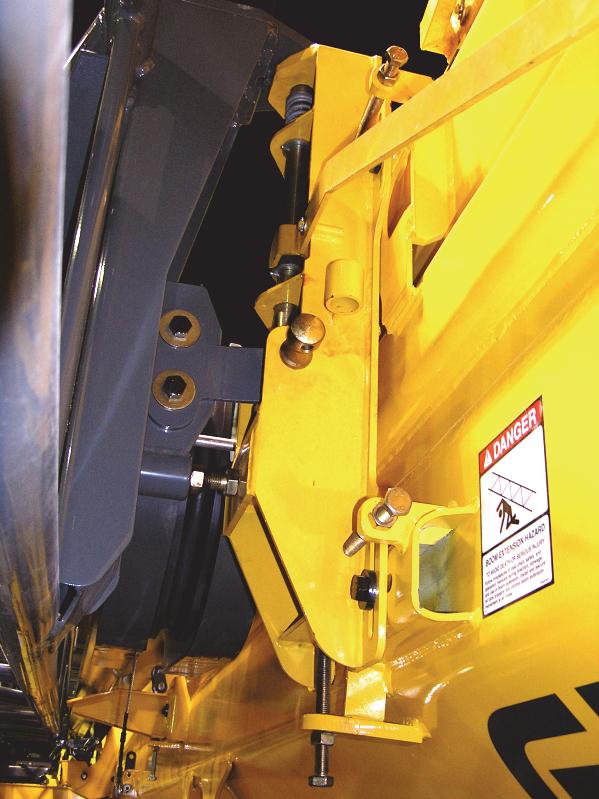
Sever injury or death may occur, boom extensions will fall from the main boom if not secured properly.
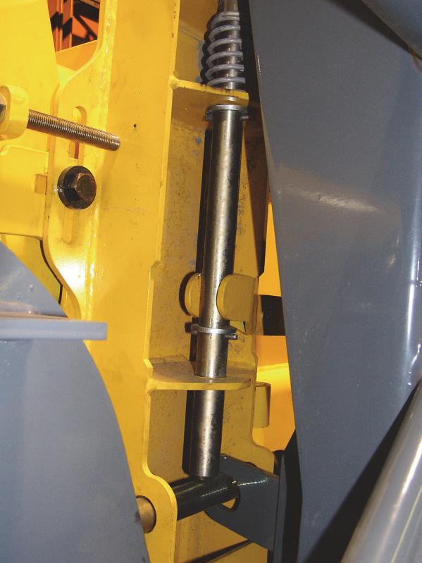
NOTE: Perform Step 16. and Step 17. if stowing the 10.1 m (33 ft) section when the 23 ft (7 m) section remained on the boom, otherwise proceed to Step 18.
16. When stowing only the 33 ft lattice boom extension. Remove the pin (1) (Figure4-62) from the main boom section locking bar (2). Move locking bar (2) to the 23 ft (7 m) bi-fold section and install pin (1). Secure with retaining pin.
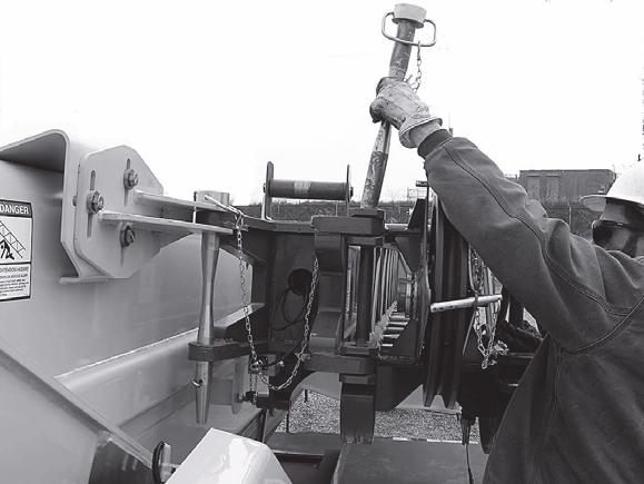
NOTE: Step 18. applies when the 7m (23 ft) section was erected with the 33 ft (10.1 m) section.
18. When stowing both the 33 ft lattice boom extension and the 23 ft bi-fold extension. Install rear stowage pin (1, (Figure4-64)) and retainer clip (2).
17. When stowing only the 33 ft lattice boom extension, remove bi-fold stowage pin (1) (Figure4-63) from bi-fold and install at the base section connection. Install retainer clip.
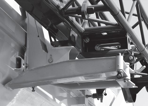
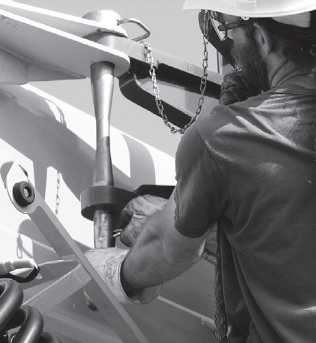
20.
(1) (Figure4-65) to stowed position.
Hose Drum for Hydraulic Luffing Boom Extension
The hydraulic supply for the lattice extension is provided through a hose drum on the left-hand side of the main boom. If the main boom is used for longer periods of time, the hose drum’s hydraulic connections should be brought into the main boom operation position. Refer to Position For Working With the Main Boom, page 4-28 in this section and (Figure4-69).
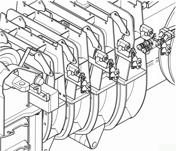
This prevents unnecessary reeling and unreeling of the hose.
The following rigging processes are described in this section:
- Locking device for transportation.
- Hydraulic connection.
Locking Devices For Transportation
The hose drum is equipped with an anti-twist device. The anti-twist device prevents the hose drum twisting unchecked against the holder when releasing the strain relief because of initial tension.
Danger
Risk of accidents from uncontrolled turning of hose drum. You may release the anti-twist device only when you have attached the strain relief on the main boom beforehand. By doing this, you prevent the hose drum from twisting uncontrollably against the holder and the turning hydraulic hoses injuring other people.
You must always insert the anti-twist device before releasing the strain relief (1) from the holder (2) on the main boom (Figure4-66).
You may release the anti-twist device only after you have attached the strain relief (1) back in the holder (2) on the main boom.
There are eight bores distributed over the radius on the inner flanged wheel of the hose drum.
Inserting Anti-Twist Device
• Turn the hose drum until a bore is in front of the spring latch (3) (Figure4-67).
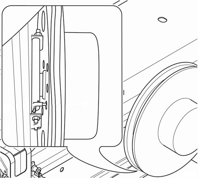
• Move the spring latch into the bore, the hose drum is secured against twisting.
Removing Anti-Twist Device
• Attach the strain relief on the main boom before removing.
• Withdraw spring latch (3) from the bore in the flanged wheel.
Hydraulic Connection
Before operating the lattice extension, you must establish the hydraulic connection. Before working with the main boom for longer periods, you must disconnect the hydraulic connections.
Caution
Risk of accidents from hydraulic hoses springing back! If you detach the strain relief after the anti-twist device has been released, do not under any circumstances let go of the strain relief before it has been reattached. If you let go of the strain relief, the hydraulic hoses will spring back uncontrollably due to the spring force in the hose drum and may injure persons or damage parts of the crane.
Position for Working with the Lattice Extension
• Take the strain relief out of the holder (1) and pull the hydraulic hoses (2) towards the main boom head.
• Hook the strain relief onto the holder (3).
• Guide the hydraulic hoses through the guide rollers (4) (Figure4-68).
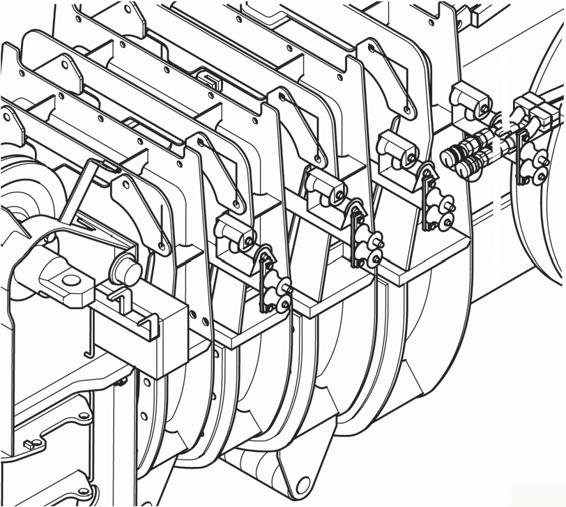
• Release the strain relief on the holder (3) and attach the strain relief to the holder (1).
Position For Working With the Main Boom
• Remove the hydraulic hoses from the guide rollers (4) (Figure4-69).
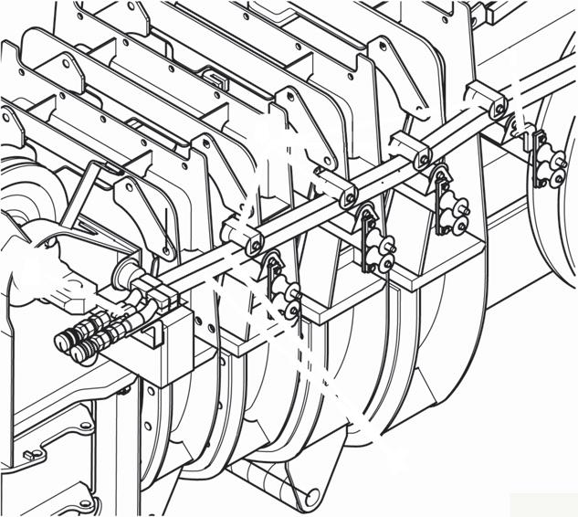
Raising and Lowering the Hydraulic Boom Extension
NOTE: For more information on operation of the boom extension switches, refer to Operating Controls and Procedures, page 3-1
When Erecting
To remotely raise or lower the lattice extension when erecting there are two control units each with two push buttons on the 33 ft (10.1 m) section.
• Press the top push-button to raise the lattice extension (1).
• Press the bottom push-button to lower the lattice extension (2).
During Operation
During operation the lattice extension is raised or lowered from the crane cab. The lattice extension can be raised or lowered, only when the power for the lattice extension is switched on.
When the power is switched on:
- The indicator lamp in the on/off rocker switch on the lattice extension lights up brightly.
- Activation of the power is shown on the RCL display.
• If necessary, switch on the power of the lattice extension, by pressing the lattice extension on/off rocker switch.
To raise, press the switch to the rear.
To lower, press the switch to the front.