17 minute read
OPERATING CONTROLS AND PROCEDURES


nine (9) volts, engine ECM voltage is below (9) volts, or there is no alternator charge signal present.
If the engine is running and the Battery Charge Indicator illuminates, investigate possible alternator, alternator fuse, or alternator wiring problems.
When the engine is not running and the Ignition Switch is in the ACC or RUN position, the Battery Charge Indicator turns on to indicate the batteries are being drained and not being charged.
Rt800e Operator Manual
Voltmeter
The Voltmeter (battery) Gauge (29) (Figure3-7) is located in the steering column gauge display. The voltmeter indicates the voltage being supplied to or from the battery and has a scale of 10 to 16 volts.
Tachometer
The Tachometer (30) (Figure3-7) is located in the steering column gauge display. The tachometer registers engine rpm and is calibrated in rpm x 100 with a range of zero [0] to 35. The tachometer receives a signal from the engine ECM.
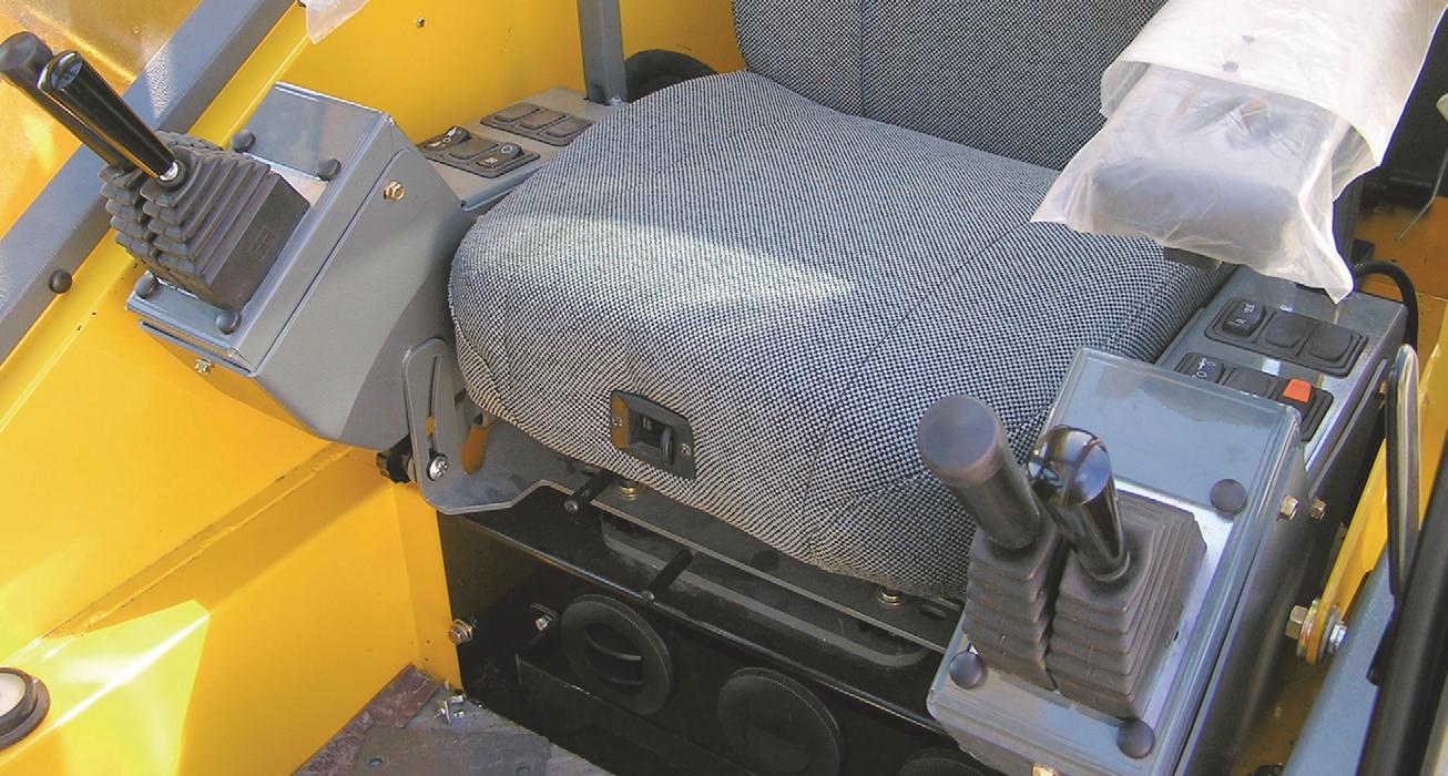
CONTROL SEAT ASSEMBLY - SINGLE AXIS
Item Description
1Main Hoist Control, Raise/ Lower
2Boom Lift Control
3Main Hoist Speed Switch
4Boom In/Out (Auxiliary Hoist Raise/Lower)
5Swing Control, Left/Right
6Auxiliary Hoist Speed Switch
7Rear Steer Switch
8Swing Brake Control Switch
9Axle Differential Lock Control Switch
10 Cab Door Release
11Seat Back Adjustment
12AC/Heater Vents
13Seat Slide Lever
14Whole Seat Slide Lever
15Right Arm Rest Adjustment
16AC/Heater Climate Control Unit
17Cab Tilt Switch
18Luffing Jib Raise/Lower Switch
ItemDescription
19Luffing Jib On/Off Switch
20Swing Speed Switch
Main Hoist Control (Single Axis Option)
The Main Hoist Control (1) (Figure3-9) is located on the right armrest. The joystick, when pushed forward, lowers the cable. When pulled back, it raises the cable.
Boom Lift Control (Single Axis Option)
The Boom Lift Control (2) (Figure3-9) is located on the right armrest. The joystick, when pushed forward (lowers the boom) or pulled back (raises the boom).
Boom Lift and Main Hoist Control Lever (Dual Axis Option) (Not Shown)
The Boom Lift/Main Hoist Control Lever is located on the right armrest. The controller, when pushed to the right (lowers the boom) or left (raises the boom).
When used for main hoist, the controller, when pushed forward (lowers the cable) or pulled back (raises the cable).
Main Hoist Speed Selector Switch
The Main Hoist Speed Selector Switch (3) (Figure3-9) is a three positioned maintained switch (High/Off/Low) that is located on th e right armrest. Positioning the switch to high position allows main hoist functions and energizes the Main Hoist High Speed Solenoid, resulting in high line speeds. Positioning the switch to the center off position will prevent hoisting. Positioning the switch to the low position allows main hoist functions and de-energizes the Main Hoist High Speed Solenoid, resulting in low line speeds.
Telescope or Auxiliary Hoist Control (Single Axis Option)
The Telescope or Auxiliary Hois t (Tele or Aux) Control (4) (Figure3-9) is located on the left armrest. The joystick controls the telescope functions when the crane is not equipped with an auxiliary hoist. Push the joystick forward to telescope the boom out, or pull the joystick back to telescope boom in.
When equipped with an auxiliary hoist, the joystick controls auxiliary hoist functions and telescope functions are controlled through a foot pedal. Push the joystick forward to let out the hoist cable or pull the lever back to reel the cable in.
Swing Control (Single Axis Option)
Danger
Crushing Hazard!
Death or serious injury could result from being crushed by moving machinery.
Before actuating swing or any other function, sound horn and verify that all personnel are clear of rotating and moving parts.
The Swing Control joystick (5) (Figure 3-6) located on the right armrest, controls the swing function. The joystick, when positioned forward (rotates the turntable clockwise) or back (rotates the turntable counterclockwise), actuates a control valve through hydraulic pilot pressure to provide 360 degree continuous rotation in the desired direction.
Swing and Telescope or Swing and Auxiliary Hoist Control Lever (Dual Axis Option) (Not Shown)
Danger
Crushing Hazard!
Death or serious injury could result from being crushed by moving machinery.
Before actuating swing or any other function, sound horn and verify that all personnel are clear of rotating and moving parts.
The Swing and Telescope or Auxiliary Hoist (Swing/Tele or Swing/Aux) Control Lever is located on the end of the left armrest. The lever controls the swing and telescope functions when the crane is not equipped with an auxiliary hoist. When equipped with an auxiliary hoist, the lever controls swing and auxiliary hoist functions and telescope functions are controlled through a foot pedal.
If not equipped with an auxiliary hoist, positioning the lever to the left or right actuates a control valve through hydraulic pilot pressure to provide 360 degree continuous rotation in the desired direction. Positioning the lever forward actuates the control valve to telescope the boom out and pulling the lever back actuates the boom to telescope in.
If equipped with an auxiliary hoist, positioning the lever forward actuates the control valve to let out hoist cable and pulling the lever back reels the cable in. Moving the lever in a diagonal direction actuates the two functions simultaneously.
Auxiliary Hoist Speed Selector Switch (Optional)
The Auxiliary Hoist Speed Selector Switch (6) (Figure3-9) is a three positioned maintained switch (High/Off/Low) that is located on the left armrest. Positioning the switch to high position allows auxiliary hoist functions and energizes the Auxiliary Hoist High Speed Solenoid, resulting in high line speeds. Positioning the switch to the center off position will prevent hoisting. Positioning the switch to the low position allows auxiliary hoist func tions and de-energizes the Auxiliary Hoist High Speed Solenoid, resulting in low line speeds.
Rear Steer Switch
The Rear Steer Control Switch (7) (Figure3-9) is a threeposition, spring centered to off, rocker switch, located on the left armrest. Press the bottom of the switch to actuate a control valve to turn the rear wheels to the left, causing the crane to turn to the right. Press the top of the switch actuates a control valve to turn the rear wheels to the right, causing the crane to turn to the left. When the wheels are not centered the Rear Wheels Not Centered light on the steering column illuminates. Releasing the switch causes it to return to the center off position.
To straighten the rear wheels press the switch until the Rear Wheels Not Centered indicator light goes off.
Swing Brake Control Switch
The Swing Brake Control Switch (8) (Figure3-9) is located on the left arm rest. This two-position rocker switch (ON/ OFF) is used to control a hydraulic valve that directs a regulated flow of pressure to and from the swing brake. Positioning the switch to ON will apply the swing brake and positioning the switch to OFF will release the swing brake. When the switch is in the ON position, the red indicator light on the steering column is illuminated. The switch has a lock to prevent accidental activation.
Axle Differential Lock Control Switch
(Optional)
NOTE: The differential lock will only work when the crane is in the 4WD mode.
The Differential Lock (Axle Diff) Control Switch (9) (Figure3-9) is located on the left arm rest. It is a two position, momentary rocker switch placarded LOCK and UNLOCK. When positioned to LOCK, the splines on the shift collar are engaged with the splines on the differential case and the axle shafts and the differential assembly are locked together and there is no differential action between the wheels. When positioned to UNLOCK, there is normal differential action between the wheels all the time. The amber indicator on the steering column is illuminated when the switch in each axle is activated.
Caution
Axle Damage!
Operating the machine with the differentials in the locked position while maneuvering on improved surfaces may result and damage to the axles.
Cab Door Release
Use the cab door release lever (10) (Figure3-9) to open and close the cab door from inside the cab.
Seat Back Adjustment
To adjust the back of the seat press the adjustment knob (11) (Figure3-9) and then adjust the seat as needed.
A/C Heater, Climate Control
The Air Conditioner/Heater Climate Control unit (16) (Figure3-9) is located in the cab under the driver’s seat. The vents (12) are part of the climate control unit and can be adjusted to direct the flow of air.
Seat Slide Lever
Moving the Seat Slide Lever (13) (Figure3-9) will slide the seat only either forward or backward.
Seat/Frame Slide Lever
Moving the Seat Slide Lever (14) (Figure3-9) will slide the seat and the seat frame either forward or backward.
Armrest Adjustment
The Armrest and armrest controls can be adjusted using adjustment knob (15) (Figure3-9). Loosen the knob and rotate the entire armrest to the desire position, retighten the knob when finished making the adjustment.
Hoist Rotation Indicators
The Hoist Rotation Indicators for the auxiliary and main hoist is located on top of each hoist control lever (1,4) (Figure3-9). Each indicator is electronically driven by an input signal from a sensor attached to its related hoist and an output signal from a control module. Each hoist control lever (1,4) pulses when its hoist is running so the operator’s thumb can sense it.
Cab Tilt Switch
The Cab Tilt switch (17) is located in the right arm rest. It is a three position, momentary spring centered to off rocker switch. It has two labeled positions, up and down, allowing the cab to be tilted either up or down.
NOTE: The Parking Brake must be engaged to operate the Cab Tilt feature and the cab must be completely down for the drive functions to be enabled.
Luffing Jib Raise/Lower Switch (Optional)
The Luffing Jib Raise/Lower Switch (18) is located on the right armrest. It is a three position, momentary switch (Lower/ Off/Raise) that energizes a solenoid to actuate the luffing jib cylinder, raises or lowers the jib when the Luffing Jib On/Off switch is ON.
Luffing Jib On/Off Switch (Optional)
The Luffing Jib Two Position On/Off Switch (19) is located on the right armrest. When in the ON position it energizes the Luffing Jib Raise/Lower switch to operate the luffing jib.
Two-Speed Swing Switch
The Two-Speed Swing switch (20) is located on left armrest. This two-position (fast/slow) switch determines the swing motor speed. When in the fast position, the swing speed high solenoid is energized.
Armrest Switch (Not Shown)
The Armrest Switch is a proximity switch located in the left hand armrest. The left hand armrest must be in the down position before crane functions can be activated.
Seat Switch (Not Shown)
This switch is located in the seat. An operator must be sitting in the seat before the crane functions can be activated. SIDE CONTROL PANEL
ItemDescription
9Bubble Level Indicator
10Boom Not Sync Indicator
11Hose Reel Brake
123rd Wrap Indicator (optional)
13Cold Weather Indicator (optional)
14 Ambient Temperature LED Indicator (optional)
15 Telescope Cylinder Charge Indicator (If Equipped)
Rated Capacity Limiter (RCL) and Work Area Definition System Control Panel
The RCL and Work Area Definition System Control Panel (1) (Figure3-10) is located on the right side of the cab. It maintains the controls and indicators for the crane’s Rated Capacity Limiter (R CL) System and Work Area Definition System. Refer to the RCL Manual for detailed information.
Rated Capacity Limiter (RCL) Bypass Switch
The RCL Bypass (Override) Swit ch (2) (Figure3-10) is a momentary type switch, turn the key to the ON position (right) to disengaged the RCL controls. Releasing the key allows the RCL controls to re-engage.
The RCL will be bypassed only as long as the switch is in the ON position.
Turning the key switch to the ON position re-engages the boom down, telescope out and winch up controls. These functions were disabled when an overload condition was sensed by the Rated Capacity Limiter (RCL). It is important to read and understand the RCL Override Warning information in the RCL Operator Manual before using the RCL Bypass switch (2) or the RCL on/off switch.
Emergency Stop Switch
ItemDescription
1Rated Capacity Limiter (RCL) Display
2Rated Capacity Limiter (RCL) Bypass Switch
3Emergency Stop Switch
4Transmission Oil Temp Gauge
5AC/Heater Vent
6Turntable Pin Swing Lock Control
712 Volt Receptacle
8Diagnostic Connector
The crane Emergency Stop Switch (3) (Figure3-10) is located on the right cab console and is used to shut down the crane’s engine. Push the red button in to shut down the engine, which illuminates the Emergency Stop indicator on the steering column. Rotate the knob and pull out to resume normally operation.
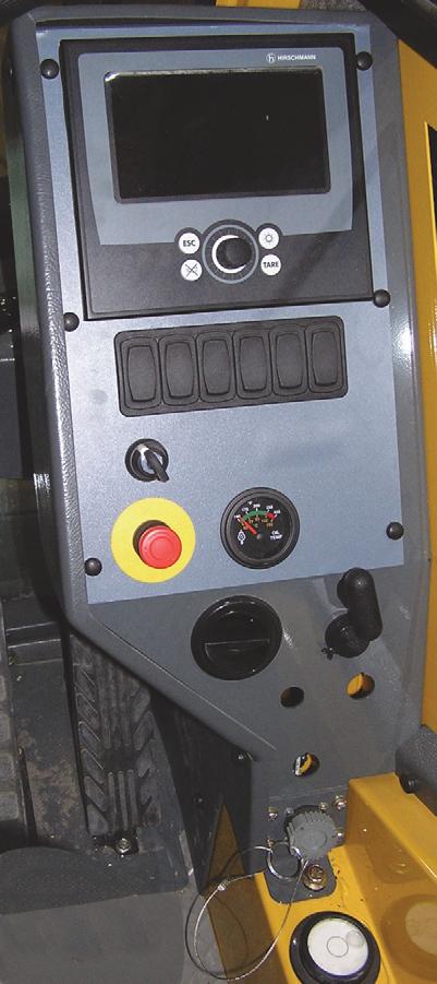
Transmission Oil Temperature Gauge
The Transmission Oil Temperature (TRANS TEMP) Gauge (4) (Figure3-10) is located in the center of the right console. The gauge indicates the transmission oil temperature on a dual scale calibrated from 60 to 160 °C and 140 to 320 °F. The gauge receives a signal from a temperature sending unit in the oil line at the torque converter.
Rt800e Operator Manual Operating Controls And Procedures
Turntable Pin Swing Lock Control
The Turntable Pin Swing Lock Control handle (6) (Figure3-10) is located on the right control panel. The purpose of the pin swing lock is to lock the superstructure in position directly over the front for pick and carry loads.
When the control handle is pushed in and the superstructure is directly over the front, the swing lock pin drops into the socket on the carrier frame, locking the superstructure in place.
When the control handle is pulled out, the pin is pulled out of the socket, unlocking the superstructure.
Caution
Swing Lock Damage! Do not engage the Pin Swing Lock while superstructure is in motion. Center boom over the front and engage Pin Swing Lock to prevent superstructure rotation during travel.
12V Receptacle
This 12 volt accessory outlet (7) (Figure3-10) is located on the lower part of the control panel and is designed to mate with most 12 volt adapter plugs.
Diagnostic Connector
The Diagnostic Connector (8) (Figure3-10) is located on the lower part of the front control panel. It is used for servicing the crane’s electrical system.
A laptop computer with a nine pin cable connector and the appropriate service software are required. Contact your local Grove distributor or Manitowoc Crane Care for assistance.
Bubble Level Indicator
The Bubble Level Indicator (9) (Figure3-10) is located on the left side of the cab by the door latch plate. The indicator provides the operator with a visual aid in determining the levelness of the crane.
NOTE: To ensure a true reading always make sure the cab is completely lowered.
Hose Reel Brake Indicator
The Hose Reel Brake ON indicator (10) (Figure3-10) is located on the right side console. It illuminates red when the Hose Reel Brake is applied and the telescope control foot pedal is in neutral.
NOTE: Do not telescope the boom in or out when the indicator light is on and the telescope control foot pedal is depressed.
Boom Not Sync Indicator
The Boom Not Sync Indicator (11) (Figure3-10) is located on the right side console. It illuminates red when the boom sections are no longer telescoping in the correct synchronization. The Boom Mode and Boom Telescope Section Select switches must then be used to correct the synchronization. This indicator light is controlled be the RCL.
Hoist Third Wrap Indicator (Optional— Standard in CE)
The Hoist 3rd Wrap Indicator (12) (Figure3-10) is located on the right side console. The indicator will illuminate red when three wraps or less of cable remains on either hoist.
Cold Weather Indicator (Optional)
The optional Cold Weather Indicator (13) (Figure3-10) is located on the right side console. The indicator comes on when ambient temperature is at or below -20°F (-29°C). It serves as a warning for the operator to stop operation in extreme cold.
Telescope Cylinder Charge Indicator (If Equipped)
The Telescope Cylinder Charge Indicator (15) (Figure3-10) is located on the right side control panel and is part of the telescope cylinder charge system. The telescope cylinder charge system is designed to prevent boom retraction due to thermal contraction under the following operating conditions: If the crane is operated with a long boom length and low boom angle, and the hydraulic oil in the telescope cylinders cools and contracts, the friction forces in the extended boom will prevent the boom from retracting. Then, if the operator begins to elevate the boom without telescoping out slightly, the crane may reach a boom elevation angle where the weight of the boom sections and load overcomes the friction forces in the boom sections, causing the boom to retract until the column of oil inside the cylinders once again supports the boom sections. The telescope cylinder charge system will prevent the boom from retracting under these conditions by automatically replenishing the volume of hydraulic oil lost in the telescope cylinders due to thermal contraction.
The telescope cylinder charge system operates automatically and does not require any operator input. The indicator illuminates amber and the buzzer sounds (2), (Figure3-13) when the boom is elevated above 35° and the telescope cylinder charge system is not functioning properly. If the buzzer sounds and th e indicator illuminates, the operator should immediately telescope out slightly to manually charge the telescope cylinders, stop operation, then have the system repaired as necessary.
NOTE: The telescope cylinder charge system does not prevent thermal contraction of hydraulic oil due to a drop in temperature and will only prevent boom retraction when the crane’s engine is running and the boom angle is greater than 35°. The system is designed only to prevent boom retraction that may occur due to thermal contraction under the operating conditions previously described.
Ambient Temperature LED Indicator
The Ambient Temperature LED Indicator (14) (Figure3-10) is located on the right side console. When the ambient temperature outside the crane reaches below -20°F (-29°C) the LED indicator will illuminate and send a signal to the RCL system. This temperature control is to prevent operation of crane lifting functions in temperatures below -20°F (-29°C). The system will initiate lockout of the following crane functions: hoist up, boom down, and boom telescopeextend. Hoist lowering, boom up and boom telescope-retract along with lockout override, will still be operational to lower the load.
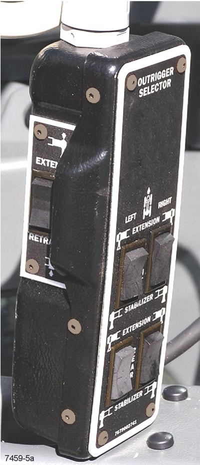
Outrigger Control
Item Description
1Hand Held Control
2Right Front Extension/Right Front Jack
3Left Front Extension/Left Front Jack
4Right Rear Extension/Right Rear Jack
5Left Rear Extension/Left Rear Jack
6Retract O/R
Cab Outrigger Control
The Cab Hand-held Outrigger Control (1, Figure3-11) is stowed in the cab (Figure3-1) and is used to control the outriggers from inside the cab.
Extend/Retract Switch
The Extend/Retract Switch (6,7 Figure3-11) is located on the side of the Outrigger Control Box and is used in conjunction with the Outrigger Selector Switches (2,3,4,5 Figure3-11) to control the outrigger functions.
Outrigger Selector Switches
There are four Outrigger Selector Switches (2,3,4,5 Figure3-11) on the Outrigger Control Box. To extend or retract an outrigger component, first select the component with the Outrigger Selector Switch (2,3,4,5), then select extend or retract with the Extend/retract Switch (6,7 Figure3-11).
NOTE: The park brake must be engaged for the outriggers to operate.
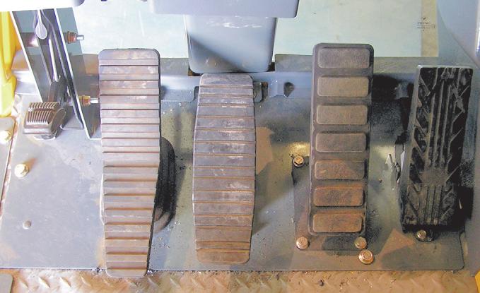
Foot Pedal Controls
7Extend O/R FIGURE3-12
Figure3-12 Item Numbers
ItemDescription
1360° Swing Lock Pedal
2360° Swing Lock Release Lever
3Swing Brake Pedal
4Telescope Control Foot Pedal (Optional)
5Service Brake Foot Pedal
6Foot Throttle Pedal
360° Swing Lock Pedal
The 360° Swing Lock Pedal (1) (Figure3-12) is located on the left side of the crane cab floor. The pedal is used to activate the swing lock to prevent the turret from turning. To release the swing lock, pull up on the 360° Swing Lock Release Lever (2).
Swing Brake Pedal
The Swing Brake Pedal (3) (Figure3-12) is located on the left side of the cab floor. The swing brake pedal is used to actuate the swing brake to slow or stop swing motion. Braking is proportional to pedal depression. With the pedal not depressed and the swing brake control valve disengaged, hydraulic pressure is applied to the brake, overcoming spring pressure and releasing the brake. Depressing the pedal actuates a swing power brake valve to apply pressure to the brake assembly. This pressure aids the spring pressure to overcome the hydraulic pressure being applied to the brake release circuit and applies the spring brake according to the pressure from the swing power brake valve.
Telescope Control Foot Pedal (Optional)
The Telescope Control Foot Pedal (4) Figure3-12 is supplied when the crane is equipped with an auxiliary hoist, it is located on the left side of the cab floor. Pushing forward on the top of the pedal will extend the boom and pushing down on the bottom of the pedal will retract the boom.
Service Brake Foot Pedal
The Brake Foot Pedal (5) (Figure3-12) is the second pedal from the right on the cab floor. Depressing the pedal controls the application of the service brakes.
Foot Throttle Pedal
The Foot Throttle Pedal (6) (Figure3-12) is located under the RCL display module, on the floor. It is used to control engine RPM which increases or decreases proportionately with the amount of foot pressure applied to the pedal. The pedal is electrically connected to the superstructure control module which sends the signal to the engine ECM via the J1939 data link.
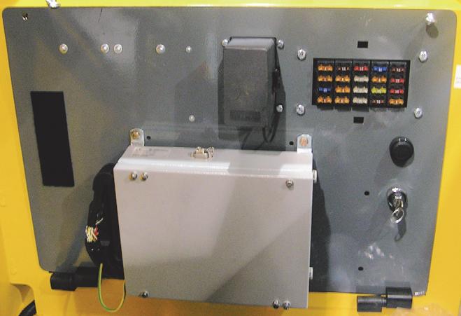
MISCELLANEOUS CONTROLS AND INDICATORS Fuse Panel
The Fuse Panel (1) (Figure3-13) is located behind the cab seat and on the cab fuse and relay panel assembly. It contains up to 20 fuses that protect the various electrical components of the crane.
Buzzer
The buzzer (2), located behind the cab seat, sounds when the following conditions exist:
• the ignition switch is turned to RUN; buzzer will sound for two seconds
• after the engine is started until the proper hydraulic oil pressure is reached
• engine stop
• emergency stop switch activated
• transmission service
• low brake pressure
• high hydraulic oil temperature
• high transmission oil temperature
• hose reel brake pressure warning
• boom not synchronized
• low steer pressure condition (for CE units)
• hoist third wrap condition (for CE units).
Rated Capacity Limiter (RCL) Emergency Override Switch (Non-CE Certified Cranes)
Warning
Loss of RCL Monitoring Hazard!
The RCL Emergency Override switch is to be used in emergency situations only.
Do not operate the crane with the RCL overridden during normal operations.
When the RCL is overridden always have a helper on the ground to signal you.
The RCL system, when programmed accurately, will lockout the three craning functions—boom down, telescope extend, and hoist up—when a lift is attempted at or above the crane's capacity or when a two-block condition exists. Locking out these three functions prevents the overload or two-block condition from worsening.
The RCL emergency override switch (3, Figure3-13) is a key operated switch that is located inside the operator cab on the panel assembly behind the seat. When actuated (turned clockwise), the switch will override and prevent the RCL from locking out the three craning functions (boom down, telescope extend, and hoist up) should an overload or twoblock condition occur.
Overriding the RCL with this switch should only be done in the case of an emergency or when servicing the boom.
A flashing light on the RCL display indicates the switch has been activated.
Refer to the RCL operator's manual for more information.
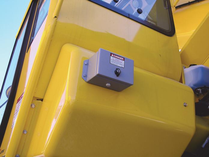
The RCL emergency override switch is located inside a keylocked single-door enclosure (1, Figure3-14) that is attached to the outside rear of the operator's cab. The switch is a two-position momentary rocker switch with integral indicator that, when actuated, will override and prevent the RCL, for a period of 30 minutes, from locking out the three craning functions (boom down, telescope extend, and hoist up) should an overload or two-block condition occur.
Overriding the RCL with this switch should only be done in the case of an emergency or when servicing the boom.
The indicator in the override switch will illuminate red and the RCL and A2B override indicators on the RCL display will flash to indicate the switch has been activated. Upon activation, all craning function movements are reduced to 15% of their normal maximum speeds.
The RCL override function is automatically cancelled after 30 minutes. The RCL override function can also be cancelled by the operator by either pressing the RCL emergency override switch a second time, by turning off the engine, or by turning the crane function power switch off.
Refer to the RCL operator's manual for more information.
Rated Capacity Limiter (RCL) Emergency Override Switch and Indicator (CE Certified Cranes)
Warning
Loss of RCL Monitoring Hazard!
The RCL Emergency Override Switch is to be used in emergency situations only.
Do not operate the crane with the RCL overridden during normal operations.
When the RCL is overridden, always have a helper on the ground to signal you.
The RCL system, when programmed accurately, will lockout the three craning functions—boom down, telescope extend, and hoist up—when a lift is attempted at or above the crane's capacity or when a two-block condition exists. Locking out these three functions prevents the overload or two-block condition from worsening.
RCL Internal Light Bar (Optional)
The Rated Capacity Limiter (RCL) Internal Light Bar is located on the upper left hand corner of the crane cab. The RCL is an operational aid that warns a crane operator of approaching overload conditions and over hoist conditions that could cause damage to equipment and personnel.
Strobe Light or Beacon (Optional) (Not Shown)
The Strobe Light or Beacon is on the roof of the cab. It is on when the ignition switch is on.