19 minute read
OPERATING CONTROLS AND PROCEDURES


Rt800e Operator Manual
Controls And Indicators
The engine is electronically controlled by the Electronic Control Module (ECM); it is th e control center of the entire engine system. The ECM processes all of the inputs and sends commands to the fuel systems as well as vehicle and engine control devices. This Operator Manual does not include information on the engine ECM, however a separate manual as prepared in detail by the engine manufacturer is shipped with the crane from the factory.
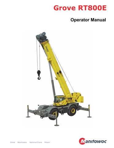
All the controls and indicators to operate and monitor crane functions are found inside the crane cab Figure3-2 and include the following:
1. Foot Pedals
2. Outrigger Control
3. Seat Joystick and Armrest Controls
4. Side Display Panel
5. Steering Column
6. Overhead Control Panels
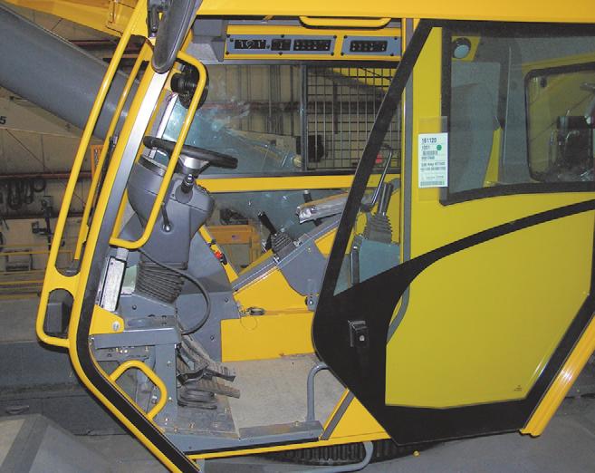
Steering Column
The steering column assembly in Figure3-2 is a pedestal style tilt and telescoping steering column. It has the ability to tilt forward 30° or be raised vertically approximately 2.5 inches. It also includes the ignition switch and the Canbus gauge display (11) (Figure 3-2).
ItemDescription
6Hazard Lights Switch
7Engine Diagnostic/Speed Control Switch
8Increment/Decrement Switch
9Ignition Switch
10Transmission Shift Lever
11Gauge Display
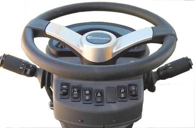
Turn Signal Lever and Windshield Wiper/ Washer/Headlight /Horn Controls
The Turn Signal Lever and Windshield Wiper/Washer Controls (1) (Figure3-2) are located on the left side of the steering column. Pushing the turn signal lever down causes the left front and left rear turn signals to flash. Pushing the turn signal lever up causes the right front and right rear turn signals to flash.
The windshield wiper switch is incorporated in the turn signal lever. The knob of the lever has three positions: O, I, and II. Pushing the button in the end of the knob energizes the windshield washer pump to spray washer fluid on the windshield. Positioning the knob to I operates the wiper at low speed and positioning the knob to II operates the wiper at high speed. Positioning the knob to O turns the wiper motor off and automatically returns the wiper to the parked position.
Pushing the small button on the end of the lever sounds the horn.
Steering Column Tilt Lever
The steering control column can be rotated forward approximately 30° and raised approximately 2.5 inches. Move the control lever (2) (F igure3-2) down to lock the steering column in place; rotating the lever up releases the steering column for the require adjustments.
Park Brake Control Switch
ItemDescription
1 Turn Signal Lever and Windshield Wiper/ Washer/Headlight /Horn Controls
2Steering Column Tilt Lever
3Park Brake Control Switch
4Headlights Switch
5Drive Axle Selector Switch
The Park Brake control switch (3) (Figure3-2) is located on the front of the steering column. This two-position rocker switch (ON/OFF) is used to apply and release the parking brake on the drive line. The red Park Brake Indicator light on the steering column is illuminated when the pressure switch in the brake release system is activated and the brake is applied.
Headlights Switch
The Headlights Switch (4) (Figure3-2) is located on the front of the steering column. This three-position rocker switch (OFF/Park/Headlight) controls operation of the instrument lights, switch LED’s, and the marker lights on the front, rear, and side of the crane. When the switch is in the ON position, the steering column and switch lights are illuminated.
Drive Axle Selector Switch
The Drive Axle Selector Switch (5) (Figure3-2) is located on the front of the steering column. This two-position rocker switch is labeled 2WD HI (high range) and 4WD LO (low range). The switch controls a solenoid valve (energized for 2WD HI) that operates the speed range and axle disconnect cylinders on the transmission. When the switch is in the 4WD LO position, the Drive Axle Indicator light on the steering column is illuminated.
Hazard Lights Switch
The Hazard Lights Switch (6) (Figure3-2) is located on the front of the steering column. The switch is a two-position rocker switch (ON/OFF) that causes the four turn signal lights to flash at the same time when the switch is positioned to ON. When the switch is positioned to ON, the turn signal indicator lights on the steering column will flash.
Engine Diagnostic and Engine Speed Control Switches
Two engine diagnostic and speed control switches (Engine Diagnostic/Speed Control and Increment/Decrement) are located on the front of the steering column.
Engine Diagnostic/Speed Control Switch
The Engine Diagnostic/Speed Control Switch (7) (Figure3-2) is a two position maintained on/off rocker switch used to access the engine fault codes or enable the control of the low engine idle and engine rpm functions.
Diagnostic function — With the Ignition Switch in the RUN position and the engine off, press the top of the Engine Diagnostic/Speed Control Switch to view the engine fault codes on the steering column display. If there is more than one active engine fault code, use the Increment/Decrement Switch (8) (Figure3-2) to toggle forward and backward through the fault codes. If there are no engine fault codes, zeroes will be shown in the steering column display.
Engine low idle function — With the engine running and the top of the Engine Diagnostic/Speed Control Switch pressed, the engine low idle is adjusted using the Increment/ Decrement Switch (8) (Figure3-2).
Engine rpm function — With the engine running and the bottom of the Engine Diagnostic/Speed Control Switch pressed, the engine rpm is adjusted using the Increment/ Decrement Switch (8) (Figure3-2).
Increment/Decrement Switch
The Increment/Decrement Switch (8) (Figure3-2) is a three position momentary rocker switch with center maintained position being off. Use this switch to toggle backward and forward through active engine fault codes or adjust engine speed.
Diagnostic function — With the Ignition Switch in the RUN position, the engine off, and the top of the Engine Diagnostic/ Speed Control Switch (7) (Figure3-2) pressed, press the top or bottom of the Increment/Decrement Switch to toggle forward and backward through the engine fault codes shown on the steering column display. If there are no engine fault codes, zeroes will be shown in the steering column display.
Engine low idle function — With the engine running and the top of the Engine Diagnostic/Speed Control Switch (7) (Figure3-2) pressed, press the top or bottom of the Increment/Decrement Switch to increase or decrease the low engine idle.
Engine rpm function — With the engine running and the bottom of the Engine Diagnostic/Speed Control Switch (7) (Figure3-2) pressed, the Increment/Decrement Switch is used to adjust engine rpm. Quickly press the top of the switch once to go to full engine rpm; quickly press the bottom of the switch once to return to low engine idle. If the engine speed is below the maximum rpm setting, pressing and holding the top of the switch will cause the engine rpm to slowly increase; release the switch when the desired rpm is attained. If the engine speed is above the minimum rpm setting, pressing and holding the bottom of the switch will cause the engine rpm to slowly decrease; release the switch when the desired rpm is attained.
Ignition Switch
The Ignition Switch (9) is located on the right side of the steering column and under the transmission shift lever(10). The switch is key-operated and has four positions: ACC [3], OFF [0], RUN [1], and START [2]. In the OFF position, all electrical power is off except for the lights controlled by the Headlights Switch, turn/hazard/stop lights, dome light and work light. Positioning the switch to ACC energizes all electrical components except for the start solenoid and engine ECM. Positioning the switch to RUN is the same as ACC. Positioning the switch to START energizes the start relay, which in turn energizes the cranking motor solenoid and cranks the engine for starting. The switch is spring returned from START to RUN. To shut down the engine, position the switch to OFF.
The Ignition switch has a mechanical anti-restart built into it. If the engine does not start after the first attempt, the key switch must go to the OFF position and then back to START in order to try and start the engine another time.
Transmission Shift Lever
Caution
Transmission Damage!
To prevent transmission damage: shift between twowheel and four-wheel drive only with the crane stopped with the transmission in neutral or park.
The Transmission Shift Lever (10) (Figure3-2) is located on the right side of the steering column. The control lever operates the transmission selector valve electrically. Positioning the lever up actuates forward and positioning the lever down actuates reverse. When the lever is in neutral, it rests in a detent. To move the lever up or down, pull back on the lever first. To shift the transmission to first, second, or third gear, rotate the knob to 1, 2, or 3.
The transmission has six forward gears and six reverse gears. To use the three low gears, put the Drive Axle switch at 4WD LO. To use the three high gears, put the Drive Axle switch at 2WD HI.
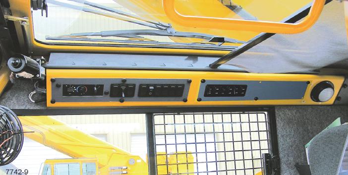
Cab Overhead Controls
Skylight Window Latch
The Skylight Window Latch (1, (Figure3-3)) is at the front of the window. Squeeze the latch and slide the window to the rear to open. to close slide the window forward until the latch engages.
Skylight Wiper and Wiper Motor
The Skylight Wiper (2, Figure3-3) is controlled by the wiper switch, (4) (Figure3-4), and operated by the Wiper Motor.
Skylight Sunscreen
The Skylight Sunscreen (3, Figure3-3) is used to diminish direct sunlight. The sunscreen is self retracting and can be set to screen all the light or adjusted rearward by moving it into the notches provided.
Dome Light
The cab Dome Light (4, Figure3-3) is on the right rear corner of the cab overhead console and provides illumination in the cab. The dome light is controlled by a switch on the light.
Cab Circulating Fan
The Cab Circulating Fan (5, Figure3-3) is located on the left front side of the cab, above the window frame. A swivel allows the fan to be rotated and a switch on the fan base controls the fan. The switch has a high, low and off position.
Right Side Window Latch
The window on the right side of the cab can be opened. Squeeze latch (6, Figure3-3) to release the window and slide forward. To close slide the window rearward until the latch engages.
Overhead Control Panel
ItemDescription
1Skylight Window Latch
2Skylight Wiper & Motor
3Skylight Sunscreen
4Dome Light
5Cab Circulating Fan
6Window Latch
7Overhead Control Panels
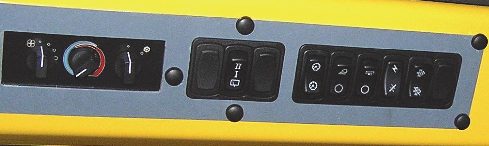
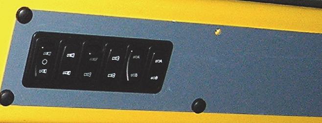
Figure3-4 Item Numbers
ItemDescription
3Air Conditioning Switch
4Skylight Wiper Switch
5Panel Dimmer Switch
6Work Lights Switch
7Boom LightS Switch (Optional)
8Crane Function Power Switch
9DPF Regeneration Switch (Tier 4 engine only)
Heater/Air Conditioner Fan Switch
The Heater/Air Conditioner Fan Switch (1) (Figure3-4) controls the cab fan’s speed. Fan speed controls the volume of heated air output (or cooled air output) of the fan. Settings are off, low speed, medium speed, and high speed.
Heater Control Switch
The Heater Control Switch (2) (Figure3-4) controls intensity of heating temperature. Turn the switch to the right (clockwise) to open the valve for heat. (Heat comes from heated fluid going through the heater coil.) Turn the switch to the left (counterclockwise) to close the valve to stop fluid flow and minimize heat.
Air Conditioner Switch
The Air Conditioning Switch (3) (Figure3-4) controls the operation of the optional air conditioning system. Settings are off (O) and on (I).
Skylight Wiper Switch
The electrically-operated Skyl ight Wiper is installed to remove moisture from the skylight. The Skylight Wiper is controlled by the Skylight Wiper Switch (4) (Figure3-4). This is a 3 position switch OFF/LOW speed/HIGH speed.
Panel Dimmer Switch
The Panel Dimmer Switch (5) (Figure3-4) controls the lighting for the overhead heater/air conditioning controls and the Transmission Oil Temperature Gauge.(7) (Figure3-3), push the switch to increase or decrease the panel lighting.
Work Lights Switch
The Work Lights Switch (6, (Figure3-4)) controls the crane’s work lights mounted on the bottom front of the superstructure cab. Press the top of the switch to turn on the work lights. Press the bottom of the switch to turn off the work lights.
Boom Lights Switch (Optional)
The Boom Lights Switch (7) (Figure3-4) is located on the side display panel. This two-position rocker switch (ON/OFF) controls operation of the boom flood lights. Press the top of the switch to turn on the boom lights, press the bottom of the switch to turn the lights off.
Crane Function Power Switch
The Crane Function Power Switch (8) (Figure3-4) is located on the side display panel. This two-position (ON/OFF) rocker switch permits the operator to disconnect power from the crane functions controlled by the hydraulic remote controllers on the armrests. Po sitioning the switch to OFF prevents inadvertent operation of functions due to bumping the controllers while roading or any other operation. With the switch in the OFF position, operation of the high speed hoist is also prevented.
DPF Regeneration Switch (Tier 4 Engines Only)
Warning
Fire or Burn Hazard!
During the regeneration process the exhaust becomes very hot. Do not park the vehicle near flammable objects. Use caution near the exhaust tailpipe during regeneration as it will become very hot.
The Engine DPF (Diesel Partic ulate Filter) Switch (9) (Figure3-4) is located on the right side of the overhead control panel. This switch is a three position switch, Inhibit Regen/Permit Regen/Start Regen. Press this switch to start engine regeneration or to disable regeneration:
• Start Regeneration (7649-10)
• Inhibit Regeneration (7649-11)
To manually regenerate, set the crane parking brake, the crane transmission must be in neutral and have all pedals released. Refer to Diesel Particulate Filter (Tier 4 Engines Only) , page 3-10 for a description of when manual regeneration is needed.
Set up a safe exhaust area around the crane; remove tools, rags, grease or any debris from the engine exhaust area. With the engine idling push the DPF Regen Switch (9) to initiate regeneration.
Within 5 seconds the engine should rev up to 1000 to 1400 rpm. The engine will continue to run at this speed for up to 45 minutes.
As a warning, the light (1, Figure3-5) above the exhaust pipe (2) will flash during regeneration.
Pressing the brake or throttle pedal during regeneration or activating the Inhibit Regen switch will interrupt the regeneration process.
Make sure the crane and surrounding area are monitored during manual regeneration. If any unsafe condition occurs, shut off the engine immediately.
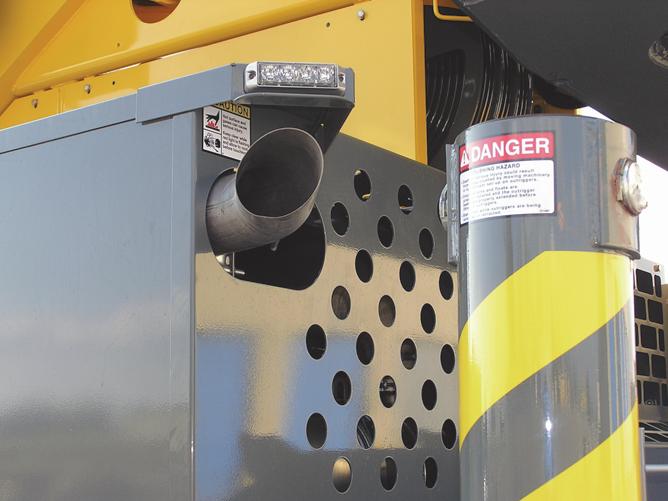
During this period the sound of the engine may change. When regeneration is complete the engine will return to it’s idle speed.
Boom Inner Mid/Center Mid (IM/CM) Select Switch and Indicator
The Inner Mid/Center Mid (IM/CM) Boom Telescope Section select switch (1) (Figure3-6) and indicator (11) are located on the overhead control panel. This switch is a three position rocker switch that is used in conjunction with the Boom Manual/Auto Telescope Mode switch (3) (Figure3-6).
When the Boom Mode switch (3) is positioned to manual, the Boom Telescope Section Select switch may be positioned to either of the two positions. When placed in the upper position, the center mid can be extended. When the center mid is fully extended, the outer mid and fly can be controlled.
The IM/CM indicator (2) will illuminate when the switch is positioned in either inner mid or center mid position.
Boom Manual/Auto Switch
The Boom Manual/Auto Telescope Switch (3) (Figure3-6) and indicator (4) are located on the overhead control panel. The switch is a two-position rocker switch placarded auto and manual.
When the switch is in the auto mode, the boom sections extend in a predetermined sequence when telescoping the boom. The sections retract in the same manner in reverse order.
When in the manual mode the switch indicator (4) will illuminate and the Boom Telescope Section Select switch is positioned to either the center mid or inner mid position in order to extend or retract the selected section until it is returned to the proper position for normal boom synchronization to occur.
Boom A/B Mode Switch and Indicator
ItemDescription
1Boom IM/CM Select Switch
2Boom IM/CM Indicator
3Boom Manual/Auto Switch
4Boom Manual/Auto Indicator
5Boom A/B Mode Switch
6Boom A/B Mode Indicator
The Boom Telescope Mode A/B select switch (5) and indicator (6) ((Figure3-6)) are located on the overhead control panel.
The five section boom is operated either automatically or manually. The manual mode of operation is used mainly to place the boom back into synchronization or for rigging and maintenance purposes. In manual operation, the operator selects which boom section is to be extended or retracted.
The automatic mode has two modes; A and B. These two modes are used when lifting and are controlled by the RCL System. The A mode retains the inner mid section fully retracted until all other sections are fully extended. The B mode begins by extending the inner mid first.
Steering Column Indicator And Gauge Display
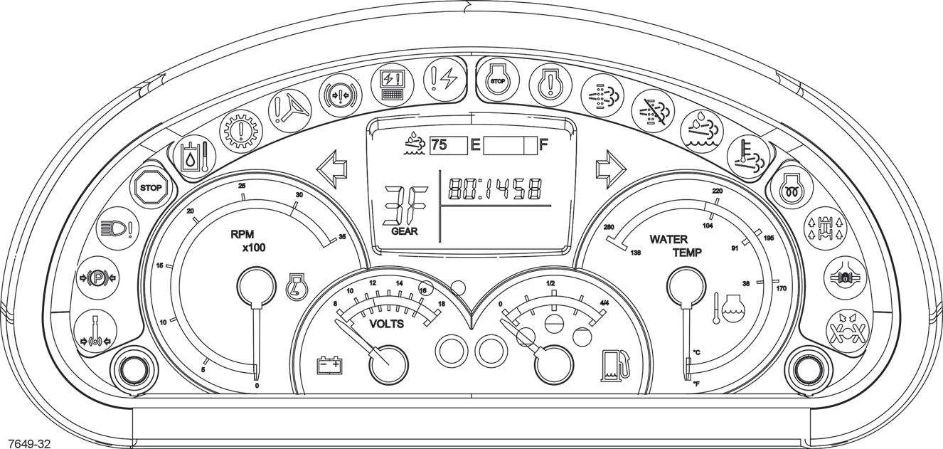
As a system check, the indicators will come on for two seconds when the Ignition Switch is turned to the RUN position.
1Swing Brake Engaged
2Parking Brake Engaged
3Light Malfunction
4Emergency Stop
5Hydraulic Oil High Temperature
6Transmission Warning
7Low Steer Pressure
8Left Turn Signal
9Low Brake Pressure
10Electronic Module Control
11 Electrical System Diagnostics
12LCD Display
13Engine Stop
14Engine Warning
15DPF, Regeneration Required
16Right Turn Signal
17Inhibit Regeneration
18Not Used
19High Exhaust System Temperature
20Engine Wait to Start
21Four-Wheel Drive Engaged
22Axle Differential Locked
23Rear Wheels Not Centered
24Push Button Switch (not used)
25Engine Coolant Temperature Gauge
26Fuel Gauge
27Low Fuel Level Indicator
ItemDescription
28Battery Charge Indicator
29Voltmeter
30Tachometer
31Push Button Switch (not used)
Swing Brake Engaged
The Swing Brake Engaged Indicator (1) (Figure3-7) is located in the steering column gauge display. It illuminates red when the Turntable Swing Motor Swing Brake is engaged preventing the rotation of the crane superstructure.
Parking Brake Engaged
The Parking Brake Engaged Indicator (2) (Figure3-7) is located in the steering column gauge display. It illuminates red when the crane parking brake is engaged.
Light Malfunction
The Light Malfunction Indicator (3) (Figure3-7) is located in the steering column gauge display. It illuminates amber when the crane headlights are malfunctioning.
Emergency Stop
The Emergency Stop Indicator (4) (Figure3-7) is located in the steering column gauge display. It illuminates red when the Emergency Stop Switch is pushed in (refer to Emergency Stop Switch, page 3-16) and a warning buzzer will sound.
Hydraulic Oil High Temperature
The Hydraulic Oil High Temperature Indicator (5) (Figure3-7) is located in the steering column gauge display. It illuminates red when the hydraulic oil temperature exceeds 200°F (93°C); a warning buzzer will also sound. When this indicator illuminates; set down the load as soon as possible, turn off the engine and try to find the cause of the high hydraulic oil temperature.
Transmission Warning
The Transmission Warning Indicator (6) (Figure3-7) is located in the steering column gauge display. It illuminates red during high transmission oil temperature conditions. A warning buzzer will also sound.
Low Steer Pressure (Optional on CE Units)
The Low Steer Pressure Indicator (7) (Figure3-7) is located in the steering column gauge display. It illuminates red when the hydraulic pressure is low. A warning buzzer will also sound.
Left Turn Signal Indicator
The Left Turn Signal Indicator (8) (Figure3-7) is located in the steering column gauge display. It is a green arrow light that flashes when the turn signal lever is pushed down or the HAZARD light switch is positioned to ON.
Low Brake Pressure
The Low Brake Pressure Indicator (9) (Figure3-7) is located in the steering column gauge display. It illuminates red when the pressure in the dual accumulator charge valve falls below normal operating requirements. A warning buzzer will also sound.
Electronic Module Indicator
The Electronic Module Indicator (10) (Figure3-7) is located in the steering column gauge display. If any of the electronic modules are off-line and not communicating with the system the indictor illuminates red.
Electronic System Diagnostic
The Electronic System Diagnostic Indicator (11) (Figure3-7) is located in the steering column gauge display. The indicator is a red light that is used for troubleshooting the CANBUS system.
A laptop computer with appropriate service system software are required. Contact your local Grove distributor or Manitowoc Crane Care.
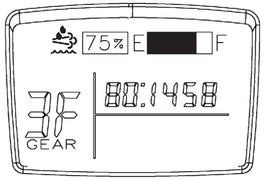
LCD Display
The LCD Display(12) (Figure3-7) is located in the steering column gauge display. The display shows the transmission gear being used, fault codes, and master software version. If an active engine fault code is present, the display will show the code when the Ignition Switch is in the RUN position and the engine is off. The display will show the master software version when the Ignition Switch is in the ACC position.
Diesel Particulate Filter (Tier 4 Engines Only)
The Diesel Particulate Filter (DPF) Indicator (15) (Figure3-7) is located in the steering column gauge display. This indicator illuminates amber when the diesel particulate filter is getting filled with soot and needs to be cleaned out.
When the DPF indicator illuminates or flashes, start regeneration process.
The indicator will be lit continuously during the early stages of clogging. If the system continues to clog, the lamp will begin to flash and slight engine derate will occur.
If even more clogging occurs, the engine warning light (14) will illuminate in addition to the DPF indicator (15) and severe engine derate will occur.
WARNING
Extreme Heat Hazard!
During the regeneration process the exhaust becomes very hot. Do not park the vehicle near flammable objects. Use caution near the exhaust tailpipe during regeneration as it will become very hot.
The regeneration process can take place in three different modes:
Figure3-8 Item Numbers
ItemDescription
Engine Stop
The Engine Stop Indicator (13) (Figure3-7) is located in the steering column gauge display. It illuminates red when a signal is sent from the engine ECM. In addition, a warning buzzer will also sound.
If this indicator light illuminates, note the fault code, shut the engine off and refer to the Engine Operator Manual.
Engine Warning
The Engine Warning Indicator (14) (Figure3-7) is located in the steering column gauge display. It illuminates amber when a signal is sent from the engine ECM.
If this indicator light illuminates, note the fault code and see Engine Operator Manual.
The Engine Warning Indicator may also illuminate with the Diesel Particulate Filter Indi cator or Diesel Exhaust Fluid Indicator.
Passive: the exhaust is hot enough during normal working operation to burn off any hydrocarbon (soot) accumulation
Active : Active self-regeneration occurs when there is not sufficient heat in the exhaust to convert all the hydrocarbon being collected in the DPF. Exhaust temperatures are raised by injecting a small amount of fuel. The resulting chemical reaction raises exhaust gas temperatures high enough to oxidize the hydrocarbon from the filter. This is all done without any operator intervention.
Manual: Manual or stationary, regeneration is the same as active regeneration but takes place while the equipment is not being operated. It offers the equipment operator the option, if needed, of performing regeneration outside the normal duty cycle.
Right Turn Signal Indicator
The Right Turn Signal Indicator (16) (Figure3-7) is located in the steering column gauge display.It is a green arrow light that flashes when the turn signal lever is pushed up or the Hazard Light switch is positioned to ON.
Inhibit Regeneration
The Inhibit Regeneration Indicator (17) (Figure3-7) is located in the steering column gauge display. When the Regen Switch (9) (Figure3-4) is in the inhibit regeneration position, this amber indicator is illuminated and active and manual regeneration is prevented.
Diesel Exhaust Fluid (Tier 4 Engines—2014 Only)
The Diesel Exhaust Fluid (DEF) Indicator (18) (Figure3-7) is located in the steering column gauge display. The indicator has four different stages which will be triggered by the fluid level sensor in the DEF tank.
Low Tank - First warning to the operator is that the reducing agent in the tank is low. The DEF indicator lamp (18) will be lit continuously.
Derate - The DEF indicator lamp (18) will start to flash as a warning to the operator that a derate will be activated if the reducing agent in the DEF tank is not refilled.
Low Level Inducement - The DEF indicator (18) will flash and the engine warning indicator (14) will be lit continuously. Derate will be activated at this stage.
Severe Inducement - Once the DEF (18) tank is empty, the crane operation will be restricted. The DEF indicator (18) will flash and the stop engine indicator (13) is solid red.
High Exhaust System Temperature
The High Exhaust System Temperature (HEST) Indicator (19) (Figure3-7) is located in the steering column gauge display.
During regeneration it is possible for the engine exhaust to reach temperatures exceeding 1200°F. The HEST indicator will illuminate red to warn the operator of when temperatures reach 1247°F (675°C) and will stay on until the temperatures falls below 1157°F (625°C).
Warning lights near the tailpipe will flash during regeneration when high exhaust temperatures exist.
For more information on the regeneration process, refer to Diesel Particulate Filter (Tier 4 Engines Only), page 3-10
Engine Wait-to-Start
The Engine Wait-to-Start Indicator (20) (Figure3-7) is located in the steering column gauge display. It illuminates amber for a period of time when the ignition switch is in the ON position. The engine should not be cranked until the Wait-To-Start light turns off. This light is controlled by the engine ECM.
Four-Wheel Drive Engaged
The Four-Wheel Drive Indicator (21) (Figure3-7) is located in the steering column gauge display. It illuminates amber when the Drive Axle Selector Switch (5) (Figure 3-2) is in the four-wheel low position. This i ndicator will also blink if the crane is shifted between two-wheel high and four-wheel low and the brake pedal is not depressed and the transmission is not in neutral.
Axle Differential Locked
The Axle Differential Locked Indicator (22) (Figure3-7) is located in the steering column gauge display. This indicator illuminates amber after the Differential Lock switch (10) (Figure3-9) is pressed to the LOCK position and the carrier differential lock switches located on each axle are closed. When in the LOCK position there is no differential action between the wheels.
Rear Wheels Not Centered Indicator
The Rear Wheels Not Centered Indicator (23) (Figure3-7) is located in the steering column gauge display. The indicator is an amber light that will illuminate any time the rear wheels are not centered.
Engine Coolant Temperature Gauge
The Engine Coolant Temperature (water temp) Gauge (25) (Figure3-7) is located in the steering column gauge display. The gauge indicates the engine coolant temperature on a dual scale calibrated from 38 to 138°C and 100 to 280°F. The gauge receives a signal from the engine ECM and a temperature sending unit in the engine cooling system.
Fuel Gauge
The Fuel Gauge (26) (Figure3-7) is located in the steering column gauge display. The gauge indicates the quantity of fuel in the fuel tank and has a scale calibrated from zero [0] to 4/4. The fuel gauge receives a signal from a sending unit in the fuel tank.
Caution
Engine Damage Hazard!
Ultra low sulfur diesel fuel required in Tier 4 engines. If “Ultra Low Sulfur” fuel in not used in engines that require it, the Cummins warranty will be void and the engine performance will quickly deteriorate and may stop running.
Low Fuel Level
The Low Fuel Level Indicator (27) (Figure3-7) illuminates when the fuel level in the tank is nearing empty (15%). When this indicator comes on fuel should be added to the fuel tank immediately. The light will go out when the fuel tank level reaches 20% of capacity.
Battery Charge Indicator
With the engine running, the Battery Charge Indicator (28) (Figure3-7) illuminates red if battery system voltage is below