3 minute read
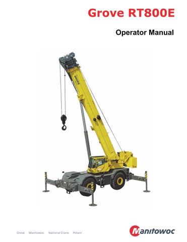
OPERATOR MANUAL


This manual has been prepared for and is considered part ofRT800E
Crane Model Number
This Manual is divided into the following sections:
SECTION 1INTRODUCTION
SECTION 2SAFETY PRECAUTIONS
SECTION 3OPERATING CONTROLS AND PROCEDURES
SECTION 4SET-UP AND INSTALLATION
SECTION 5LUBRICATION
SECTION 6MAINTENANCE CHECKLIST
NOTICE
The crane serial number is the only method your distributor or the factory has of providing you with correct parts and service information.
The crane serial number is identified on the builder’s decal attached to the operator cab. Always furnish crane serial number when ordering parts or communicating service problems with your distributor or the factory.
An untrained operator subjects himself and others to death or serious injury. Do not operate this crane unless:
•You are trained in the safe operation of this crane. Manitowoc is not responsible for qualifying personnel.
•You read, understand, and follow the safety and operating recommendations contained in the crane manufacturer’s manuals and load charts, your employer’s work rules, and applicable government regulations.
•You are sure that all safety signs, guards, and other safety features are in place and in proper condition.
• The Operator Manual and Load Chart are in the holder provided on crane.
California Proposition 65 Warning
Diesel engine exhaust and some of its constituents are known to the State of California to cause cancer, birth defects, and other reproductive harm.
California Proposition 65 Warning
Battery posts, terminals, and related accessories contain chemical lead and lead compounds, chemicals known to the State of California to cause cancer, birth defects or other reproductive harm. Wash hands after handling.
The original language of this publication is English.
See end of this manual for Alphabetical Index
Control Lever (Dual Axis Option) (Not Shown)
Main Hoist Speed Selector Switch
Telescope or Auxiliary Hoist Control (Single Axis Option)
Swing Control (Single Axis Option)
Swing and Telescope or Swing and Auxiliary Hoist Control Lever (Dual Axis Option) (Not Shown)3-14
Auxiliary Hoist Speed Selector Switch (Optional).
Rear Steer Switch.
General
NOTE: Throughout this handbook, reference is made to left, right, front, and rear when describing locations. These reference locations are to be considered as those viewed from the operator seat with the superstructure facing forward over the front of the carrier frame.
This manual has been compiled to assist you in properly operating and maintaining your Grove Crane.
Before placing the crane in service, take time to thoroughly familiarize yourself with the contents of this manual. After all sections have been read and understood, retain the manual for future reference in a readily accessible location in the crane.
This Grove crane has been designed for maximum performance with minimum maintenance. With proper care, years of trouble-free service can be expected.
Constant improvement and engineering progress makes it necessary that we reserve the right to make specification and equipment changes without notice.
Engine operating procedures and routine maintenance procedures are supplied in a separate manual with each crane, and should be referred to for detailed information.
Information in this manual does not replace federal, state, or local regulations, safety codes, or insurance requirements.
Customer Support
Manitowoc and our Distributor Network want to ensure your satisfaction with our products and customer support. Your local distributor is the best equipped and most knowledgeable to assist you for parts, service and warranty issues. They have the facilit ies, parts, factory trained personnel, and the information to assist you in a timely manner. We request that you first contact them for assistance. If you feel you need factory assistance, please ask the distributor’s service management to coordinate the contact on your behalf.
New Owners
If you are the new owner of a Grove crane, please register it with Manitowoc Crane Care so we have the ability to contact you if the need arises.
Go to: http://www.manitowoccranes.com/MCG_CARE/ Includes/EN/changeofownership.cfm and complete the form. This manual provides important information for the operator of the Model RT890E4 Series Grove Crane.
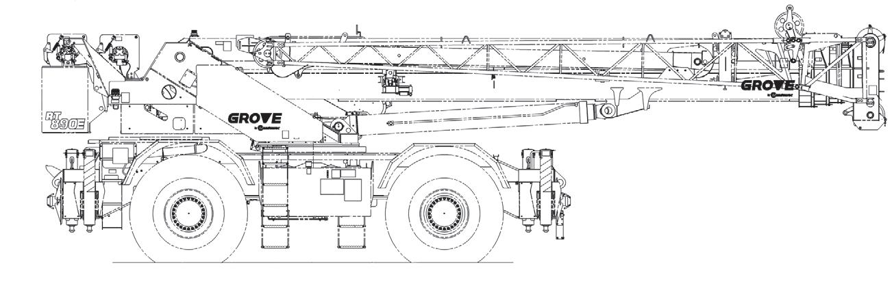
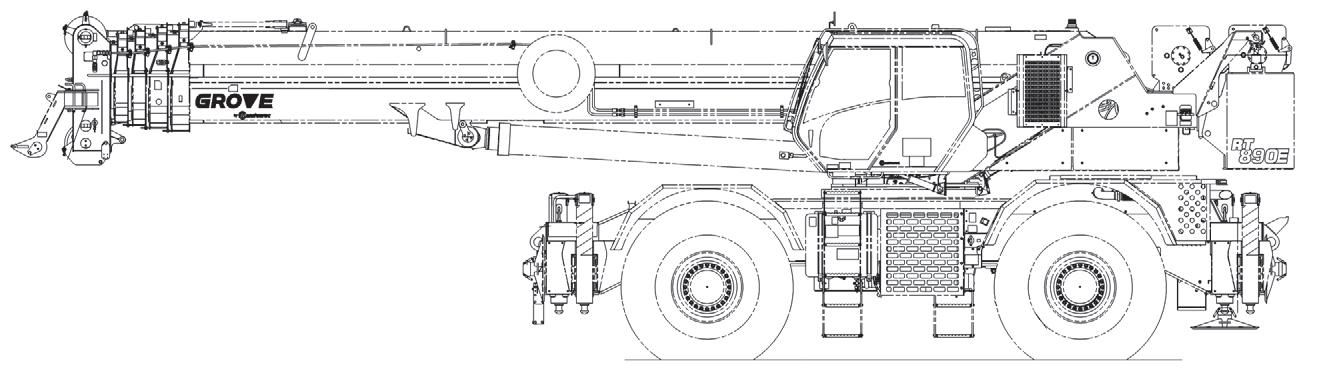
The rough terrain crane incorporates an all welded steel frame, using planetary drive axles to provide four-wheel drive. Axle steering is accomplished utilizing hydraulic steer cylinders. The engine is mounted at the rear of the crane and provides motive power through a six speed forward and reverse transmission.
The carrier frame incorporates an integral fifth wheel, to which the rear axle is mounted, to provide axle oscillation. Axle oscillation lockout is automatic when the superstructure rotates from the travel position.
The superstructure is capable of 360° rotation in either direction. All crane functions are controlled from the fullyenclosed cab mounted on the superstructure. The crane is equipped with a five-section, full power, sequenced and synchronized boom. Additional reach is obtained by utilizing an optional swingaway boom extension. Lifting is provided by a main and auxiliary hoist.
NOISE/VIBRATION TEST RESULTS
Noise Level Test Results
• When equipped with the CE certification package, the guaranteed sound power level LWA is 107dB(A) as measured by Directive 2000/14/EC and 80dB(A) at the crane operator’s position as measured by Annex G.1 of EN 13000:2010.
Vibration Level Test Results
At the operator station with closed cab operation, vibration levels are less than 0.5 m/s/s for Whole Body Vibration exposure and are less than 2.5 m/s/s for Hand Arm Vibration exposure when measured according to 89/392/ EEC Community Legislation on Machinery per standard ISO 2631/1 - Evaluation of Human Exposure to Work Body Vibration, ISO 5349 - Guidelines for the Measurement and Assessment of Human Exposure to Hand Transmitted Vibrations, and ISO/DIS 8041 - Human Response Vibration Measuring Instrumentation.
Serial Number Location
The serial number (Figure1-1) of the crane can be found:
• On the frame (1)
• Inside the cab (2)
• On the cover of this Operator Manual (3).