OPERATOR’S MANUAL Form No.
909879
418T Wheel Loader
GEHL CONSTRUCTION WARRANTY
GEHL CONSTRUCTION DIVISION of the GEHL COMPANY, hereinafter referred to as Gehl, warrants new Gehl construction equipment to the Original Retail Purchaser to be free from defects in material and workmanship for a period of twelve (12) months from the Warranty
Start Date:
GEHL CONSTRUCTION WARRANTY INCLUDES:
Genuine Gehl parts and labor costs required to repair or replace equipment at the selling dealer’s business location.
GEHL MAKES NO REPRESENTATIONS OR WARRANTIES OF ANY KIND, EXPRESS OR IMPLIED (INCLUDING THE IMPLIED WARRANTIES OF MERCHANTABILITY AND FITNESS FOR PARTICULAR PURPOSE), EXCEPT AS EXPRESSLY STATED IN THIS WARRANTY STATEMENT.
GEHL WARRANTY SERVICE DOES NOT INCLUDE:
1.Transportation to selling dealer’s business location or, at the option of the Original Retail Purchaser, the cost of a service call.
2.Used equipment.
3.Components covered by their own non-Gehl warranties, such as tires, trade accessories and engines.
4.Normal maintenance service and expendable, high wear items.
5.Repairs or adjustments caused by: improper use; failure to follow recommended maintenance procedures; use of unauthorized attachments; accident or other casualty.
6.Liability for incidental or consequential damages of any type, including, but not limited to lost profits or expenses of acquiring replacement equipment.
No agent, employee or representative of Gehl has any authority to bind Gehl to any warranty except as specifically set forth herein. Any of these limitations excluded by local law shall be deemed deleted from this warranty; all other terms will continue to apply.
Thecompletedocumentationconsistsof:
Description
Partnumber
Operator’sManual909879
Operator’sManual(Engine)
Sparepartscatalogue909880
Legend
Edition Issued
ASeptember2002
©Copyright–2002GehlCompany
PrintedintheUnitedStatesofAmerica
Allrightsreserved
Nopartofthispublicationmaybereproduced,translatedorusedinanyformorbyanymeans–graphic,electronic ormechanicalincludingphotocopying,recording,tapingor informationstorageorretrievalsystems–withoutprior permissioninwriting.
Thecoverfeaturesthemachinewithpossibleoptionalequipment.
GehlCompany
P.O.Box179
WestBend,WI53095U.S.A.
Document:909879
Partno.:909879
Edition:A
Tableofcontents
AP0902 I-1
Introduction Introduction....................................................................................................................1-1 Notesonthisoperator’smanual.............................................................................1-1 Machine:Overview...................................................................................................1-2 Briefdescription........................................................................................................1-3 Applications..............................................................................................................1-4 Regulations...............................................................................................................1-5 Machinedata............................................................................................................1-6 Typelabelsandcomponentnumbers.......................................................................1-7 Safetysignsandsymbols.......................................................................................1-8 Safetyinstructions Safetyinstructions..........................................................................................................2-1 Identificationofwarningsanddangers...................................................................2-1 Designateduses.......................................................................................................2-2 Generalconductandsafetyinstructions...................................................................2-3 Safetyinstructionsregardingoperation....................................................................2-5 Safetyinstructionsforserviceandmaintenance......................................................2-9 Warningofspecialhazards...................................................................................2-11 Operation Operation.......................................................................................................................3-1 Overviewofcab.......................................................................................................3-2 Overview:Multifunctionalleverandconsoles.........................................................3-4 Placingintoservice..................................................................................................3-5 Safetyinstructions.............................................................................................3-5 Placingthemachineintoserviceforthefirsttime.............................................3-5 Checklists..........................................................................................................3-6 Drivingthemachine..................................................................................................3-8 Overviewofcontrols:........................................................................................3-8 WarningLights:overview................................................................................3-13 Beforestartingtheengine...............................................................................3-16 Startingtheengine..........................................................................................3-16 Beforedrivingthemachine...............................................................................3-20 Driving.............................................................................................................3-22 Driveranges.....................................................................................................3-23 Differentiallock.................................................................................................3-25 Stoppingthemachine......................................................................................3-25 Parkingthemachine.........................................................................................3-26 Lightsystem.....................................................................................................3-27 Signallingsystem..............................................................................................3-28 Cabheatingandventilation..............................................................................3-29 Windowwashsystem.......................................................................................3-30 Seatadjustment................................................................................................3-31 Seatbelt...........................................................................................................3-33 Driver'sdoorandsidewindow..........................................................................3-35 Othercontrols...................................................................................................3-38 Towingandtransportingthemachine..............................................................3-39 Workingwiththemachine......................................................................................3-42 Generalsafetyinstructions..............................................................................3-42 Loaddiagram...................................................................................................3-42 Safeloadindicator............................................................................................3-43 Controlvalveforthetelescopicunit:overview.................................................3-45 Tableofcontents
I-2 AP0902 Tableofcontents Loweringthetelescopicunitwiththeengineswitchedoff................................3-47 Relievingpressurethequickcouplersonthetelescopicunit.........................3-47 Installinganattachment...................................................................................3-48 Connectingpressurizedquickcouplers...........................................................3-51 Operationofthetelescopicunit........................................................................3-53 Safetydevice“Hoseburstvalve“......................................................................3-55 Workingwithstandardbucketandpalletforks.................................................3-58 Workingwithpalletforks...................................................................................3-66 Troubleshooting Troubleshooting.............................................................................................................4-1 Enginetrouble..........................................................................................................4-2 Possiblecausesformalfunctions.......................................................................4-3 Maintenance Maintenance...................................................................................................................5-1 Introduction..............................................................................................................5-1 Fuelsystem..............................................................................................................5-1 Specificsafetyinstructions................................................................................5-1 Refuelling............................................................................................................5-2 Cleaningthefueltank........................................................................................5-3 Changingthefuelfilter........................................................................................5-4 Cleaningthefuel/waterseparator.......................................................................5-5 Bleedingthefuelsystem.....................................................................................5-6 Enginelubricationsystem.........................................................................................5-7 Checkingtheengineoillevel.............................................................................5-7 Toppinguptheengineoil..................................................................................5-7 Changingtheengineoil......................................................................................5-8 Changingtheengineoilfiltercartridge...............................................................5-9 Engineandhydraulicscoolingsystem....................................................................5-10 Specificsafetyinstructions..............................................................................5-10 Checkingthecoolantlevel/toppingupthecoolantlevel..................................5-11 Cleaningthecoolingfins..................................................................................5-12 Airfilter...................................................................................................................5-13 V-belt.......................................................................................................................5-15 CheckingtheV-belttension.............................................................................5-15 Re-tensioningtheV-belt..................................................................................5-15 Hydraulicsystem.....................................................................................................5-16 Specificsafetyinstructions..............................................................................5-16 Checkingthehydraulicoillevel.......................................................................5-16 Toppingupthehydraulicoil..............................................................................5-17 Changingthehydraulicoil...............................................................................5-17 Hydraulicoilreturnfilter....................................................................................5-20 Replacingthebreatherfilter.............................................................................5-21 Hydraulicpressurelines..................................................................................5-21 Gearboxesandaxles.............................................................................................5-22 Rearaxletransfergearbox..............................................................................5-22 Frontandrearaxledifferentials........................................................................5-24 Frontandrearaxleplanetarydrives................................................................5-25 Lubricatingtherearaxleoscillation-typebearing.............................................5-26
AP0902 I-3 Tableofcontents Maintenanceofthebrakesystem...........................................................................5-27 Specificsafetyinstructions..............................................................................5-27 Checking/toppingupbrakefluid......................................................................5-27 Telescopicunit........................................................................................................5-28 Lubricatingthepivotpointsofthetelescopicunit............................................5-28 Lubricatingthetelescopicunit.........................................................................5-28 Adjustingthewearpads...................................................................................5-29 Tirecare.................................................................................................................5-30 Inspectionwork................................................................................................5-30 Wheelchange...................................................................................................5-31 Heating...................................................................................................................5-32 Cleaningthedustfilteroftheheatingsystem..................................................5-32 Electricalsystem.....................................................................................................5-33 Specificsafetyinstructions..............................................................................5-33 Serviceandmaintenanceworkatregularintervals.........................................5-33 Instructionsconcerningspecificcomponents...................................................5-34 Generalmaintenancework.....................................................................................5-36 Cleaning..........................................................................................................5-36 Boltedconnections...........................................................................................5-38 Pivotsandhinges............................................................................................5-38 Enginefluidsandlubricants..................................................................................5-39 Maintenancekits....................................................................................................5-40 Helpfulinformationforusingtheservicepartslist Helpfulinformationforusingtheservicepartslist.........................................................6-1 Introduction..............................................................................................................6-1 Compositionofservicepartslist..............................................................................6-1 Groups...............................................................................................................6-1 Groupoverview..................................................................................................6-2 Figures................................................................................................................6-3 Numberindex....................................................................................................6-3 Symbolsandabbreviations......................................................................................6-4 Descriptionofsymbols......................................................................................6-4 Abbreviations......................................................................................................6-6 Machinedata...........................................................................................................6-6 Helpfulinformationfororderingserviceparts...........................................................6-7 Orderinformation...............................................................................................6-7 Addressforyourservicepartorder....................................................................6-8 Specifications Specifications................................................................................................................. 7-1 Frame......................................................................................................................7-1 Engine.....................................................................................................................7-1 Powertrain...............................................................................................................7-2 Axles.......................................................................................................................7-2 Brakes.....................................................................................................................7-3 Steering..................................................................................................................7-3 Workhydraulics......................................................................................................7-3 Telescopicunit........................................................................................................7-4 Electricalsystem......................................................................................................7-5 Fuseboxesinsideconsole...............................................................................7-5 Mainfusesinenginecompartment....................................................................7-6 Relays................................................................................................................7-6 Tires.......................................................................................................................... 7-7
I-4 AP0902 Tableofcontents Weights...................................................................................................................7-7 Noiselevels.............................................................................................................7-7 Vibration...................................................................................................................7-8 Dimensions.............................................................................................................7-8 Coolanttable.............................................................................................................7-9 Tighteningtorques...................................................................................................7-9 Generaltighteningtorques................................................................................7-9 Specifictighteningtorques................................................................................7-9 Conversiontables..................................................................................................7-10 Conversionfactors...........................................................................................7-10 Specificconvertedvalues................................................................................7-11 Annex Proofsofmaintenance..................................................................................................A-1 Maintenanceplanmodel418T(overview)....................................................................A-3 Maintenanceplanmodel 418T(maintenancelabel).............................................................................................A-5 Explanationofsymbolsusedinmaintenanceplan..................................................A-5 Legendforhydraulicsdiagram, model418T ❙➜ 418T0001.....................................................................................A-6 Hydraulicsdiagrammodel418T...................................................................................A-7 Electricaldiagram418T................................................................................................A-9
Fuelsystem....................................................................................5-1
Gearboxesandaxles...................................................................5-22
Generalmaintenancework..........................................................5-36
Heating.........................................................................................5-32
Hydraulicoilreturnfilter................................................................5-20
Hydraulicpressurelines...............................................................5-21
Hydraulicsystem..........................................................................5-16
Instructionsconcerningspecificcomponents...............................5-34
Lubricatingtheoscillation-typebearing........................................5-26
Lubricatingthetelescopicunit......................................................5-28
Maintenanceplan...........................................................................A-3 Pivotsandhinges.........................................................................5-38
Planetarydrives............................................................................5-25
Proofsofmaintenance...................................................................A-1
Replacingthefillerandbreatherfiltersonthehydraulicoiltank..5-21
Screwconnections.......................................................................5-38
Serviceandmaintenanceworkatregularintervals......................5-33 Telescopicunit.............................................................................5-28
Toppingupthe
Coolantlevel......................................................................5-11
Engineoil.............................................................................5-7
Hydraulicoil.......................................................................5-17
Transfergearbox..........................................................................5-22
Tirecare.......................................................................................5-30
V-belt............................................................................................5-15
Wheelchange..............................................................................5-31
AP0902 I-5 Index A Abbreviations.........................................................................................1-1 Acceleratorpedal...................................................................................3-9 Applications Attachments....................................................................................1-4 B Backupwarningsystem(option)..........................................................3-24 Biodegradableoil.................................................................................5-19 Brakeinchingpedal...............................................................................3-9 Brakesystem.......................................................................................5-27 Brakefluid.....................................................................................5-27 Safetyinstructions.........................................................................5-27 C Changingdirection...............................................................................3-24 Changingdirection,Tipswitchfor........................................................3-24 Checklists..............................................................................................3-6 Controlelements....................................................................................3-8 Controlleverforattachmentsand3rdcontrolcircuit...........................3-46 Conversionfactors...............................................................................7-10 Convertedvalues.................................................................................7-11 D Designateduseandexemptionfromliability.........................................2-2 Differentiallock....................................................................................3-25 Documents.............................................................................................1-5 Drivingdirectionselectorswitch............................................................3-8 Drivinglicence.......................................................................................1-5 Drivingonpublicroads........................................................................3-20 Drivingthemachine...............................................................................3-8 Dustfilter..............................................................................................5-32 E Electricaldiagram.................................................................................A-9 Enginecoolantpreheater(option).......................................................3-18 Enginepreheater(option)....................................................................3-18 Equipmentofthemachine.....................................................................1-5 F Fieldsofapplication Possibleattachments......................................................................1-4 Fuellevelindicator...............................................................................3-15 Fuelpreheater(option)........................................................................3-18 G Generalconduct....................................................................................2-3 H Hazardwarningsystem.......................................................................3-28 Heating................................................................................................3-29 Highbeam...........................................................................................3-27 Hydraulicoilpreheater(option)............................................................3-18 J Jump-startingtheengine.....................................................................3-19 L Lightsystem.........................................................................................3-27 Loaddiagram.............................................................................1-12,3-42 Loaderunit Checkingthetiltpositionofthebucket.........................................3-58 Lockfordrivingonpublicroads...........................................................3-46 Loweringthetelescopicunitwiththeengineswitchedoff...................3-47 M Machine Briefdescription..............................................................................1-3 Data................................................................................................1-7 Fieldsofapplication........................................................................1-4 Overview........................................................................................1-2 Machineinspections..............................................................................1-5 Maintenance Airfilter.........................................................................................5-13 Biodegradableoil..........................................................................5-19 Bleedingthefuelsystem................................................................5-6 Brakesystem................................................................................5-27 Changingthe Engineoil.............................................................................5-8 Engineoilfiltercartridge......................................................5-9 Fuelfilter..............................................................................5-4 Hydraulicoil.......................................................................5-17 Checkingthe Coolantlevel......................................................................5-11 Engineoillevel.....................................................................5-7 Hydraulicoillevel...............................................................5-16 Cleaning.......................................................................................5-36 Cleaningthe Fueltank..............................................................................5-3 Cleaningthecoolingribs..............................................................5-12 Cleaningthefuel/waterseparator..................................................5-5 Differentials..................................................................................5-24 Electricaldiagram...........................................................................A-9 Electricalsystem..........................................................................5-33 Engineandhydraulicscoolingsystem.........................................5-10 Enginelubricationsystem..............................................................5-7
Index I
I-6 AP0902 Index
Multifunctionallever.............................................................................3-11 O Operation...............................................................................................3-1
Beforemovingoff..........................................................................3-20 Beforestartingtheengine.............................................................3-16 Changingdirection........................................................................3-24 Driveranges.................................................................................3-23
Parkingthemachine.....................................................................3-26
Startingtheengine........................................................................3-16 Stoppingthemachine...................................................................3-25 Operationmanual Notes..............................................................................................1-1 P Palletforks...........................................................................................3-66 Approachingthematerial..............................................................3-66 Loadingthematerial.....................................................................3-67 Safetyinstructions........................................................................3-66 Settingdownthematerial.............................................................3-68 Parkingbrake.......................................................................................3-10 Preheatingstartswitch..........................................................................3-8 R Refuelling...............................................................................................5-2 Regulations............................................................................................1-5 Rotatingbeacon(option).....................................................................3-28 Running-inperiod..................................................................................3-5 S Safeloadindicator...............................................................................3-43 Adjustingsignalvolume................................................................3-44 Overview.......................................................................................3-43 Whattodoif.................................................................................3-44 Safetyinstructions.................................................................................2-1 Identification....................................................................................2-1 Operation........................................................................................2-6 Specialhazards............................................................................2-13 Seatadjustment...................................................................................3-31 Armrestsetting..............................................................................3-32 Backrestsetting............................................................................3-32 Heightsetting................................................................................3-31 Longitudinalsetting.......................................................................3-32 Weightsetting...............................................................................3-31 Seatbelt...............................................................................................3-33 Servicebrake.......................................................................................3-22 Signallingsystem.................................................................................3-28 Signsandsymbols.................................................................................1-9 Specifications.........................................................................................7-1 Axles...............................................................................................7-2 Brakes.............................................................................................7-3 Conversionfactors........................................................................7-10 Coolantcompoundtable.................................................................7-9 Dimensions.....................................................................................7-8 Electricalsystem.............................................................................7-5 Engine.............................................................................................7-1 Frame.............................................................................................7-1 Noiselevels....................................................................................7-7 Powertrain.....................................................................................7-2 Specificconvertedvalues.............................................................7-11 Steering..........................................................................................7-3 Telescopicunit...............................................................................7-4 Tighteningtorques..........................................................................7-9 Tires...............................................................................................7-7 Vibration.........................................................................................7-8 Weights..........................................................................................7-7 Workhydraulics..............................................................................7-3 Startingwithstartingaid......................................................................3-24 Steering...............................................................................................3-21 Symbols................................................................................................1-1 T Takingintoservice................................................................................3-5 Checklists.......................................................................................3-6 Overviewofthecontrolelements...................................................3-8 Safetyinstructions..........................................................................3-5 Takingthemachineintoserviceforthefirsttime...........................3-5 Telescopicunit Checkingthetransportpositionofthebucket..............................3-58 Depressurizingthequickcouplersonthetelescopicunit.............3-47 Loweringthetelescopicunitwiththeengineswitchedoff............3-47 Lubrication....................................................................................5-28 Re-equippingthetelescopicunit..................................................3-48 WarningLights....................................................................................3-13 Towingandtransportingthemachine.................................................3-39 Transportingwithafullbucket............................................................3-59 Turnindicators....................................................................................3-28 Typelabelsandcomponentnumbers...................................................1-8 Tirecare..............................................................................................5-30 Tireinflationpressuretable.................................................................1-11 Tires......................................................................................................7-7 V Ventilation...........................................................................................3-29 Ventilation,freshair......................................................................3-29 W Warningidentification(option)...............................................................1-5 Warranty................................................................................................2-1 Washerpump......................................................................................3-30 Washersystem Tank.............................................................................................3-30 Wheelchange.....................................................................................5-31 Wheelsynchronizationposition...........................................................3-21 Windowwashsystem..........................................................................3-30 Wipers.................................................................................................3-30 Working ...withpalletforks.........................................................................3-66 Approachingthematerial.............................................................3-66 Loadingthematerial.....................................................................3-67 Safetydevice"Hoseburstvalve".................................................3-55 Settingdownthematerial.............................................................3-68 Workinglight(option)..........................................................................3-27 Workingwiththemachine Freeingthemachine.....................................................................3-65 Grading.........................................................................................3-65 Loadingheapedmaterial..............................................................3-64 Loadingloosematerial.................................................................3-60 Practicalhints...............................................................................3-65 Removingmaterial/digginginhardsoil........................................3-63 Removingmaterial/digginginsoftsoil..........................................3-62
Maintenancekits..................................................................................5-40
Backupwarningsystem(option)...................................................3-24
Movingoff.....................................................................................3-22 Overviewofcab..............................................................................3-2 Overviewofinstrumentpanel,multifunctionalanddrivelever........3-4
Selectingdriverange....................................................................3-23
1
Section1 Introduction
1.1Notesonthisoperator’smanual
Thisoperator’smanualcontainsimportantinformationonhowtoworksafely,correctlyand economicallywiththewheelloadermodel418T.Therefore,itaimsnotonlyatnewoperators,butitisalsoareferenceforexperienced ones.Ithelpstoavoiddangeroussituations, andreducerepaircostsanddowntimes.Furthermore,thereliabilityandtheservicelifeof themachinewillbeincreasedbyfollowingtheinstructionsintheoperator’smanual.Thisis whytheoperator’smanual must alwaysbekeptinthemachine.
Yourownsafety,aswellasthesafetyofothers,dependstoagreatextentonhowthe machineismovedandoperated.Therefore,carefullyreadandunderstandthisoperator’s manualpriortothefirstuse.Thisoperator’smanualwillhelptofamiliarizeyourselfmore easilywiththemachine,therebyenablingyoutouseitmoresafelyandefficiently.
GeneralsafetyinstructionsaregiveninPart2ofthisoperator’smanual.Carefullyread andunderstandthempriortothefirstdrive.Asarule,keepthefollowinginmind: Carefulandprudentworkingisthebestwaytoavoidaccidents!
Specialsafetyinstructionswithdirectreferencetoservice,functionandoperator’softhe machinearegivenbeforetheproceduretofollowintherespectivechapters.Thesesafety instructionsmustalwaysbeobservedandfollowed.
Operationalsafetyandreadinessofthemachinedonotonlydependonyourskill,butalso onmaintenanceandserviceofthemachine.Thisiswhyregularmaintenanceandservice workisabsolutelynecessary.Extensivemaintenanceandrepairworkshouldalwaysbe carriedoutbyanexpertwithappropriatetraining.Insistonusingoriginalserviceparts whenperformingmaintenanceandrepairwork.Thisensuresoperationalsafetyandreadinessofyourmachine,andmaintainsitsvalue.
Yourdealerwillbepleasedtoansweranyfurtherquestionsregardingthemachineorthe operator’smanual.
Abbreviations/symbols
• Thissymbolstandsforalist
• Thissymbolstandsforthesubdivisionofanenumerationoranactivity.Followthe stepsintherecommendedsequence.
☞ Thissymbolrequiresyoutocarryouttheactivitydescribed.
➥ Descriptionoftheeffectsorresultsofanactivity.
n.s.=notshown
SO=option
Statedwhenevercontrolsorothercomponentsofthemachineareinstalledasanoption.
Thissymbolshowsthedirectionoftravel–forbetterorientationinfiguresand graphics.
AP0902 1–1 1 1Introduction
Introduction
1–2 AP0902 Introduction 1.2Machine:Overview
308b0070.eps 308b0060.eps
31100b0190.eps
1 Workinglight(option) 2 Dangerlabel 3 Fronteyehooks–liftingandstrappingdownthemachine 4 Wheelchock 5 Horn 6 Mark–telescopicunitpositionforlong-haultravel 7 Accesshandle 8 ProtectiveFOPSscreen 9 Noiseemissionlabel 10 ECsign 11 Maximumdrivingspeedlabel 12 Fuelfillerinlet 13 Drawbarpin 14 Reareyehooks–liftingandstrappingdownthemachine 15 Step 16 Workinglight(option) 17 Turnindicator 18 Headlights 19 Enginecoverlock 20 Label–“Donotopenenginecoverbeforeengineisata standstill!” Donottouchanymovingorturningparts! 21 Brakelight,rearlight,turnindicator 22 Rearviewmirror 2 20 6 8 9 4 5 10 11 13 14 21 21 2 20 11 1 16 22 17 18 17 18 7 15 19 12 22 3 20 14 !
Fig.1:Machineoutsideviews
1.3Briefdescription
Thewheelloadermodel418Tisaself-propelledworkmachine. Thismachineisaversatileandpowerfulhelperformovingearth,gravelanddebrisonconstructionsitesandelsewhere.Thewiderangeofattachmentsaccountsforthenumerous applicationsofthemachine:asaforklift,asnowplow,aspreaderforsand,saltetc.,a sweeperoratreereplanter.Seepart 1.4Applications forfurtherapplications.Fitthe machinewiththerespectivesafetydeviceswhenusingitasaliftingmachine(see“Applicationswithliftingaccessories”inPart2SafetyInstructions).
Themaincomponentsofthewheelloadermodel418Tare:
• ROPStestedoperator’scab
• Water-cooledfourcylinderPERKINSdieselengine,58hp(43.1kW)at2400rpm(as perDINISO9249)
• Sturdysteelsheetframeintorsion-resistantbox-typedesign
• Hydrostaticdrivewithelectroniccontrol,inching;12mph(20km/h)max.speed
• Hydrostaticfour-wheelsteeringwithemergencysteeringfeatures
• Frontandrearplanetaryaxles,rearaxlewithoscillation
• Servicebrake(mechanicalorhydrostatic),mechanicaldisk-typeparkingbrake
• Telescopicunitwithsafeloadindicator
Hydrostaticdrive
Thedieselenginedrivesahydraulicpump,whoseoilflowissenttoahydraulicmotorconnectedtotherearaxle.Theforceofthehydraulicmotoristransmittedtotherearaxlevia thetransfergearbox.Atthesametime,thefrontaxleisdrivenbythecardanshaft,ensuringpermanentfourwheeldrive.
Workhydraulicsandhydrostaticfourwheelsteering
Thedieselenginealsodrivesthejointgearpumpforworkhydraulicsandhydrostaticfourwheelsteering.Theoilflowofthispumpdependsonthedieselenginespeedonly.
Whenthemachineisinoperation,theentiredieselengineoutputcanbetransmittedtothe gearpumpforworkhydraulicsandsteering.Thisismadepossiblebytheso-calledinching whichrespondsassoonastheinchingbrakeisused,reducingorcuttingoffpowerinputof thedrive.Therefore,engineoutputisfullyavailableforthetelescopicunitbypressingthe acceleratorpedalandtheinchingbrakepedalatthesametime.
Coolingsystem
Acombinedoil/watercooler(forthedieselengineandthehydraulicoil)islocatedatthe rearofthemachine.Thewarninglightsintheinstrumentpanel 17 ensureconstantmonitoringofthecoolantandhydraulicoiltemperature.Inaddition,anaudiblesignalsoundsin themachinecabassoonasthereisdangerofcoolantorhydraulicoiloverheatingandin caseoflowengineoilpressure.
AP0902 1–3 Introduction
Introduction 1.4Applications
Theattachmentswilldeterminewhereandhowthemachinecanbeused. Thefollowingtablegivesanoverviewofthepossibleattachments.
1–4 AP0902
DescriptionandModel ModelNo. Use Standardbucketw/teeth –normalmaterial 418T 810136Loosening,pickingup,transportingandloadinglooseor solidmaterial(materialdensity ≤ 2700lbs/yd³(18kg/m³)) Palletforks 418T 810135Pickingupandtransportingpalletsperloaddiagram
1.5Regulations
Drivinglicense
Earthmovingmachineryshouldbedrivenonpublicroadsonlyifthedriverhasadrivers license.
Getinformedonandfollowthelegalregulationsofyourcountry.
Equipment
Thehighwayregulationsofyourstate/provincemayrequireyoutoequipyourmachine with:
• Slow-MovingVehicle(SMV)emblem
• warninglights
Becomeinformedonandfollowthelocalhighwayregulations.
GehlwillsendyoutheoriginalcopyofthisDeclarationofManufactureratyourrequest. Pleasestatenameofproduct,modelandidentificationnumber(seetypelabelofthe attachment).
AP0902 1–5 Introduction
Introduction
1.6Machinedata
Thefollowingdataprovideadetaileddescriptionofyourmachine.Pleasesupplyyour dealerwiththesedataforallcorrespondenceortelephoneinquiries.
Pleasereadthedatavalidforyourmachineofftheserialnumberplates,andenterthis datainthelist.Theywillimmediatelybeathandforallinquiriesorservicepartsorders.
Machinemodel:
Dateofregistration:
Servicehours/kilometerreading: ......................................................................................................................................
Serialnumber:
Cabnumber:
Engineno.: ......................................................................................................................................
Variabledisplacementpumpmodel–identificationno.:
Variabledisplacementmotormodel–identificationno.:
Frontaxleno.:
Rearaxleno.: ......................................................................................................................................
Cabno.:
Optionalattachments:
Yourlocaldealer:
• Address:
• Telephone:
1–6 AP0902
1.7Typelabelsandcomponentnumbers
Typelabel
Thetypelabel(Fig.3)islocatedatthefrontrightofthemachineframe(Fig.2 /1)
Serialnumber
Theserialnumberisstampedonthemachineframe(Fig.2/2).Itisalsostampedonthe typelabel(Fig.3)
Exampleforwheelloadermodel418T: 418T0005
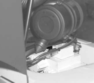
Enginenumber
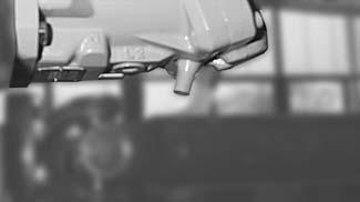
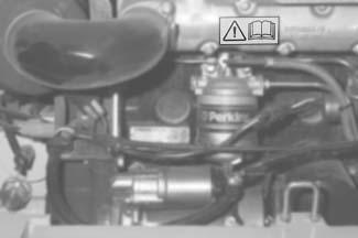
Theenginenumberislocatedonthelabelatthefrontoftheengineblock(arrow,Fig.4)
Example: 073305
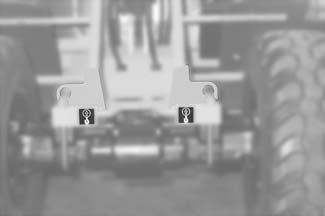
Numberofhydraulicpump
Thetypelabel(arrow,Fig.5)islocatedonthepump,belowtheairfilter
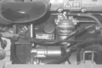
Hydraulicmotornumber
Thetypelabel(arrow,Fig.6)islocatedonthelowersideofthehydraulicmotor,abovethe cardanshaft
AP0902 1–7
Introduction
Fhzg-Typ Model Modèle 308 311 10 311 10 0003 2001 Typ Ausf. Version Version Fg.-Nr. Serial no. No. de série Baujahr Model year Anné e fabr. Zul. Achslast vorn Front GAWR PNBE AV Zul. Achslast hinten Rear GAWR PNBE AR Zul. Ges. Gew. GWR PTAC Leistung Output Performance [ kg ] [ kg ] [ kg ] [ kW ] 3750 3750 6000 43,5 31100b0230.eps
Fig.2:Typelabel:location
1 2
Fig.3:Typelabelmodel418T
Fig.4:Dieselenginenumber
Fig.5:Hydraulicpump:typelabel
Fig.6:Hydraulicmotor:typelabel
Front/rearaxlenumber
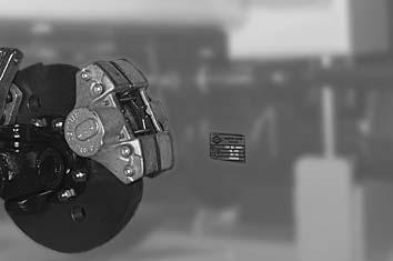
Theaxlenumberislocatedonthetypelabel,ontherightsideofeachaxle(arrow,Fig.7)
1.8Safetysignsandsymbols
Thefollowingexplainssignsandsymbolsthatdonotcontainexplanatorytext.
...ontheoutsideofthemachine
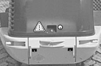
Meaning
Generalindicationofdanger:
Thissign(Fig.9)warnspersonsstandingorworkingnearthemachineofincreaseddangeraroundthemachine.
Location
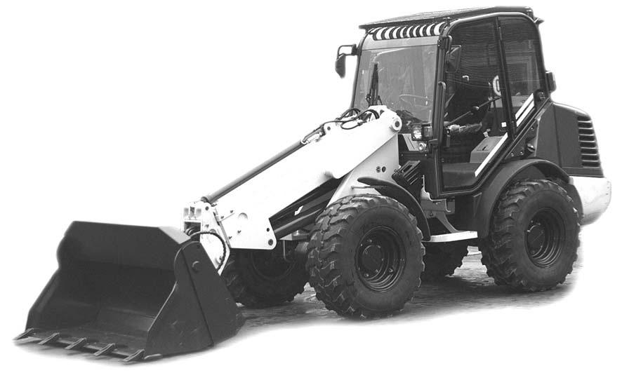
Frontleftandrightofmachineframe,andatrearofmachine(Fig.8/3)
Meaning
Eyehooks/limit(Fig.10)stopsonthemachine. Theeyehooksareusedforliftingorstrappingdownthemachine.
Location
Attherearofthecounterweight(Fig.8/2),aswellas atthefrontabovethefrontaxle,leftandrightontheframe
Meaning
1(Fig.11)Donotopenenginecoverbeforeengineisstopped!
2(Fig.11)Donottouchanymovingorturningparts!
Location
Attherearontheenginecover(Fig.8/1),aswellasontheengineblock.
1–8 AP0902 Introduction
Fig.7:Typelabelonthefrontaxle
3 3 2
Fig.8:Decalsattherear
308b0360.eps
Fig.9:Dangersign
308b0680.eps
Fig.10:Decal:eyehooks
Fig.11:Prohibitorysign
Meaning
Readandobservetheoperator’smanualbeforecarryingoutmaintenancework!
Location
Ontheengineblock(Fig.12)
AP0902 1–9 Introduction
Fig.12:Pleaserefertooperator’smanual
Introduction
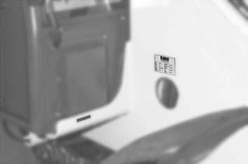
...insidetheoperator’scompartment
Meaning
Cabtypelabel(Fig.13)
Location
OnleftsideofB-column
Meaning
Reifenluftdrucktabelle
Tire pressure
Pression pneumatiques
Tireinflationpressuretable (Fig.14)
Listofauthorizedtypesoftireswithprescribedtireinflationpressure
Tires Pneumatiques
Reifenbezeichnung vorn (bar) front (bar) AV (bar)
hinten (bar) rear (bar) AR (bar)
Bei Stapelbetrieb Luftdruck vorne um 0,5bar erhöhen! Increase tire pressure by 0,5 bar during pallet forks operation! Augmenter la pression pneumatique de 0,5bar en service porte-palette!
Location
Insidethecab,onleftsideoffrontwindow
Meaning
Loaddiagram (Fig.15foroperationwithpalletforks(forkarms):
Theframednumbersindicatethemaximumauthorizedloadontheforkarmsforindustrial (S=1.25)andoff-road(S=1.67)applicationsrespectively.Themaximumloadvaries accordingtothehorizontalandverticaldistanceoftheloadcenter,inthediagramdepicted ontheforkarmswithadistanceof500mmtotherearoftheforkarms.Thetelescopicunit withforkarmsmoveswithinthedottedrange.
Readingexampleforattachmentno.810135:

Off-roadapplication ➝ safetyfactorS=1.67
Distanceofloadtorearofforkarms=20inches(500mm)
Heightofforkarmabovetirecontactarea=61inches(1.56m)
Distancetotirefront=132inches(3.36m)
Maximumloadis2061lbs(935kg)!
1–10 AP0902
Fig.13:Cabinspectionlabel
31100b0010.eps
Fig.14:Tyreinflationpressuretablemodel31100
Fig.15:Loaddiagram
S=1,25/ 1100 kg S=1,67/ 820 kg S=1,25/ 1270 kg S=1,67/ 950 kg S=1,25/ 1500 kg S=1,67/ 1120 kg S=1,25/ 1800 kg S=1,67/ 1345 kg 311-00 311-10
charges Gültig
Anbaugerät
for attachment Valable pour équipement Nr. 10103-00 Nr. 10149-00 Nr. 10162-00 Nr. 10165-00
31100b0210.eps
Traglastdiagramm Load diagram Diagramme de
für
Valid
Section2
Safetyinstructions 2
2Safetyinstructions
2.1Identificationofwarningsanddangers
Importantindicationsregardingthesafetyoftheoperatingpersonnelandthemachineare indicatedinthisoperator’smanualwiththefollowingtermsandsymbols:
DANGER!/WARNING!/CAUTION!
Failuretoobservetheinstructionsidentifiedbythissymbolmayresultin personalinjuryordeathfortheoperatororotherpersons.
☞ Measuresforavoidingdanger
IMPORTANT
Failuretoobservetheinstructionsidentifiedbythissymbolmayresultin damagetothemachine.
☞ Measuresforavoidingdangerforthemachine
NOTE:
Thissymbolidentifiesinstructionsforamoreefficientandeconomicaluseofthe machine.
Environment!
Failuretoobservetheinstructionsidentifiedbythissymbolmayresultindamagetothe environment. Theenvironmentisindangerifenvironmentallyhazardousmaterial(e.g.wasteoil)isnot subjecttoproperuseordisposal.
AP0902 2–1 2
Safetyinstructions
Safetyinstructions
2.2Designateduses
• Themachineisintendedfor:
• Movingearth,gravel,coarsegravelorballastandrubbleaswellas
• Workingwiththeattachmentmentionedinthepresentoperator’smanual Everyotherapplicationisregardedasnotdesignatedfortheuseofthemachine.Gehl willnotbeliablefordamageresultingfromuseotherthanmentionedabove.Theuser alonewillbeartherisk.
Designatedusealsoincludesobservingtheinstructionsintheoperator’smanualand observingtheconditionsofmaintenanceandservice
• Observethepertinentregulationsrelevanttoaccidentprevention,othergenerally acknowledgedregulationsregardingsafetyandoccupationalmedicine,aswellasthe regulationsandstandardsrelevanttomotormachinesandtraffic.Themanufactureris notliablefordamageresultingfromthefailuretoobservetheseregulations
• Thesafetyofthemachinecanbenegativelyaffectedbycarryingoutmachinemodificationswithoutproperauthorityandbyusingspareparts,equipment,attachmentsand optionalequipmentwhichhavenotbeencheckedandapprovedbythemanufacturer. Themanufacturerwillnotbeliablefordamageresultingfromthis
• Themanufacturerwillnotbeliableforpersonalinjuryand/ordamagetoproperty causedbyfailuretoobservethesafetyinstructionsandtheoperator’smanual,andby thefailuretoexerciseduecarewhen:
• Handling
• Operating
• Servicingandcarryingoutmaintenancework
• Repairing themachine.Thisisalsoapplicableinthosecasesinwhichspecialattentionhasnot beendrawntothedutytoexerciseduecare,inthesafetyinstructionsaswellasinthe operator’sandmaintenancemanuals(machine/engine).
Readandunderstandtheoperator’smanualbeforestarting,servicingorrepairingthe machine.Observethesafetyinstructions!
• Themachinemaynotbeusedfortransportjobsonpublicroads
• Inapplicationswithliftingaccessories,themachineistobeusedaccordingtoitsdesignateduseonlyiftherequiredsafetydevicesareinstalledandfunctional
2–2 AP0902
2.3Generalconductandsafetyinstructions
Organizationalmeasures
• Themachinehasbeendesignedandbuiltinaccordancewithcurrentstandardsand therecognizedsafetyregulations.Nevertheless,itsusemayconstitutearisktolifeand limboftheuserorofthirdparties,orcausedamagetothemachineandtoother materialpropertyifitisnotusedproperly.
• Themachinemustonlybeusedinmechanicallygoodconditioninaccordancewithits designateduse(s)andtheinstructionssetoutintheoperator’smanual,andonlyby safety-consciouspersonswhoarefullyawareoftherisksinvolvedinoperatingthe machine.Anymalfunctions,especiallythoseaffectingthesafetyofthemachine,must thereforebecorrectedimmediately!
Basicrule:
Beforestartingthemachine,inspectthemachineforsafetyinworkandroadoperation!
• Carefulandprudentoperationisthebestwaytoavoidaccidents!
• Theoperatinginstructionsmustalwaysbeavailable,andmustthereforebekeptinthe storagecompartmentprovidedforinthecab.
Immediatelycompleteorreplaceanincompleteorillegibleoperator’smanual.
• Inadditiontotheoperatinginstructions,observeandinstructtheoperatorinallapplicablelegalandmandatoryregulationsrelevanttoaccidentpreventionandenvironmentalprotection.
Thesecompulsoryregulationsmayalsodealwiththehandlingofhazardous substances,issuingand/orwearingofpersonalprotectiveequipment,ortrafficregulations.
• Withregardtospecificoperationalfeatures,e.g.thoserelevanttojoborganization, worksequencesorthepersonsdoingthework,supplementtheoperator’smanualby correspondinginstructions,includingthoserelevanttosupervisingandreportingduties.
• Personswhowithworkonthemachinemusthavereadandunderstoodtheoperator’s manualandinparticular,Section2“SafetyInstructions”beforebeginningwork.This appliesespeciallytopersonsworkingonlyoccasionallyonthemachine,e.g.set-upor maintenance.
• Theuser/ownermustcheck–atleastfromtimetotime–whetherthepersonsdoing operationormaintenanceofthemachineareworkingincompliancewiththeoperator’s manualandareawareofrisksandsafetyfactors.
• Theuser/ownercommitshimselftooperateandkeepthemachineinagoodoperating condition,and,ifnecessaryorrequiredbylaw,torequiretheoperatingorservicing personstowearprotectiveclothingetc.
• Intheeventofsafety-relevantmodificationsorchangesonthemachineorofits behavior,stopthemachineimmediatelyandreportthemalfunctiontothecompetent authority/person. Safety-relateddamageormalfunctionsofthemachinemustbecorrectedimmediately.
• Nevermakeanymodifications,additionsor conversionstothemachineanditssuperstructure(cab,telescopicunitetc.),aswellastotheattachments,whichmightaffect safetywithouttheapprovalofthemanuufacturer!Thisalsoappliestotheinstallation andtheadjustmentofsafetydevicesandvalves,aswellastoweldingworkonloadbearingelements.
• Servicepartsmustcomplywiththetechnicalrequirementsspecifiedbythemanuufacturer.Originalservicepartsfromthemanuufacturercanbereliedtodoso.
• Replacehydraulichoseswithinstipulatedandappropriateintervalsevenifnosafetyrelateddefectshavebeendetected.
AP0902 2–3
Safetyinstructions
Safetyinstructions
• Beforeworkingonorwiththemachine,take offjewelry,suchasrings,wristwatches, bracelets,etc.,andtiebacklonghair,and donotwearloose-fittinggarments,suchas unbuttonedorunzippedjackets,tiesorscarves. Injurymayresultfrombeingcaughtupinthemachineryorfromringscatchingon movingparts!
• Keepthemachineclean.Thisreduces:
• Firehazard,e.g.duetooil-soakedragslyingaround
• Dangerofinjury,e.g.duetodirtordebrisonthesteps,and
• Dangerofaccidente.g.duetodirtordebrisonthebrakeoracceleratorpedal!
• Observeallsafety,warningandinformationsignsanddecalsonthemachine.
• Adheretoprescribedintervalsorthosespecifiedintheoperator’smanualforroutine checks/inspectionsandmaintenancework!
• Forservice,inspection,maintenanceorrepairwork,toolsandworkshopequipment adaptedtothetaskinvolvedareabsolutelyindispensable.
Selectionandqualificationofpersonnel,basicresponsibilities
• Anyworkonorwiththemachinemustbeperformedbyreliablepersonnelonly.Donot letunauthorizedpersonsdriveorworkwiththemachine!Observestatutoryminimum agelimits!
• Employonlytrainedorinstructedstaffonthemachine,andsetoutclearlyandunequivocallytheindividualresponsibilitiesofthepersonnelforoperation,set-up,maintenance andrepair!
• Definethemachineoperator'sresponsibilities –includingobservingtrafficregulations. Givetheoperatortheauthoritytorefuseinstructionsbythirdpartiesthatarecontraryto safety.
• Donotallowpersonstobetrainedorinstructed,orpersonstakingpartinageneral trainingcourse,toworkonorwiththemachinewithoutbeingsupervisedbyanexperiencedperson!
• Workontheelectricalsystemandequipment,onthechassisandonthesteeringand brakesystemsmaybecarriedoutonlybyskilledpersonnelwhohasbeenspecially trainedforsuchwork.
Workonthehydraulicsystemofthemachinemustbecarriedoutonlybypersonnel withspecialknowledgeandexperienceofhydraulicequipment!
• Sealofftheareaofdangershoulditnotbepossibletokeepasafedistance. Stopworkifpersonsdonotleavetheareaofdangerinspiteofwarning!Keepoutof theareaofdanger!
Areaofdanger : Theareaofdangeristheareainwhichpersonsareindangerduetothemovementsof the
• Machine
• Workequipment
• Additionalequipment,or
• Material
Thisalsoincludestheareaaffectedbyfallingmaterial,equipment,orbypartsthatare thrown.
2–4 AP0902
2.4Safetyinstructionsregardingoperation
Normaloperation
• Beforebeginningwork,familiarizeyourselfwiththesurroundingsandcircumstancesof theworksite.Theseare,e.g.,obstaclesintheworkingandtravellingarea,thesoil bearingcapacityandanynecessarybarriersseparatingtheworksitefrompublicroads.
• Takethenecessaryprecautionstoensurethatthemachineisusedonlywheninasafe andreliablecondition!
• Operatethemachineonlyifallprotectiveandsafety-relateddevices,e.g.,removable safety-devices,soundproofingelementsandmufflersetc.,areinplaceandfully functional!
• Checkthemachineatleastoncedaily/perworkingshiftforvisibledamageanddefects. Reportanychanges(suchaschangesinthemachine’sworkingbehavior)tothe competentorganization/personimmediately!Ifnecessary,stopthemachineimmediatelyandlockit!
• Intheeventofmalfunctions,stopthemachineimmediatelyandlockit!Haveany defectscorrectedimmediately!
• Startandoperatethemachinefromtheoperator’sseatonly!
• Carryoutstart-upandshut-downproceduresinaccordancewiththeoperator’smanual, andobservethewarninglights!
• Beforeputtingthemachine/attachmentintooperation(start-up/moving),makesure nobodyisatrisk!
• Beforedrivingthemachine,andalsoafterstoppingwork,checkwhetherthebrakes, steering,signallingandlightsystemsarefunctional!
• Beforemovingthemachinealwayscheckwhetherthesupplementaryequipmentand theattachmentshavebeensafelystowedawayorattached!
• Whendrivingonpublicroads,observethetrafficregulationsand,ifnecessary,make surebeforehandthatthemachineisincompliancewiththeseregulations!
• Inconditionsofpoorvisibilityandafterdarkalwaysswitchonthelights!
• Nolifting,loweringorcarryingofpersonsinthe workequipment/attachments!
• Nomountingofamanbasketorpersonalworkplatform!
• Whencrossingunderpasses,bridgesandtunnels,orwhenpassingunderoverhead lines,alwaysmakesurethereissufficientclearance!
• Alwayskeepatasafedistancefromtheedgesofexcavationsandslopes!
• Whenworkinginbuildingsorinenclosedareas,lookoutforthe
• Heightoftheceiling/clearances
• Widthoftheentrancesand
• Maximumloadofceilingsandfloors Provideforsufficientroomventilation–dangerofpoisoning!
AP0902 2–5
Safetyinstructions
Safetyinstructions
• Avoidanyoperationthatmightbearisktostability!
• Duringoperationonslopes,driveorworkuphillordownhill.Ifdrivingacrossaslope cannotbeavoided,bearinmindthestabilitylimitofthemachine! Alwayskeeptheattachments/worktoolclosetotheground.Thisalsoapplieswhen drivingdownhill!
Whendrivingorworkingacrossaslope,theloadmustbeontheuphillsideofthe machine.
• Onslopingterrainalwaysadaptyourdrivingspeedtotheprevailinggroundconditions. Neverchangetoalowergearonaslope,butalwaysbeforereachingit!
• Beforeleavingthemachine
• Lowertheworktool/attachmentstotheground
• Beforeleavingtheoperatorseat,alwayssecurethemachineagainstinadvertent movementandunauthorizeduse!
• Beforestartingwork,checkwhether
• Allsafetydevicesareproperlyinstalledandfunctional
• SlowMovingVehicle(SMV)embleminstalledasneeded
• Warninglightsinstalledasneeded,and
• AFirst-aidkitisonhand
• Beforemovingthemachineorbeforestartingwork:
• Makesurevisibilityissufficient(donotforgetrearviewmirrors!)
• Adjustcorrectseatposition(brakepedalmustbedepressedtothelimit). Neveradjusttheoperatorseatwhendrivingorworking!
• Fastenyourseatbelt
• Inspecttheimmediatearea(children!).Intheworkareatheoperatorisresponsible forthirdparties!
• Cautionwhenhandlingfuel–increaseddangeroffire!
Makesurefueldoesnotcomeintocontactwithhotparts!Stoptheengineduringrefuelling!Donotsmokeduringrefuelling,andavoidfireandsparks!
• Nevergetonoroffamovingmachine!Neverjumpoffthemachine!
• Ifthelightsofthemachinearenotsufficientforthesafeexecutionofcertainwork processes,provideadditionallightingoftheworkarea.
• Installedrearworklightsmustnotbeswitchedonfortravelonpublicroads.Theycan beswitchedoninworkoperationifusersofpublicroadsarenotdazzled.
• Hydrostaticfour-wheelsteeringtakestimegettingusedto.Therefore,adjustthedriving speedtoyourabilitiesandthecircumstances.Selectionandchangesteeringmodeof machineatstandstillonly!
WARNING!
Exposuretocrystallinesilica(foundinsand,soilandrocks)hasbeen associatedwithsilicosis,adebilitatingandoftenfatallungdisease.A HazardReview(Pub.No.2002-129)bytheU.S.NationalInstitutefor OccupationalSafetyandHealth(NIOSH)indicatesasignificantrisk(at least1in100)ofchronicsilicosisforworkersexposedtoinhaledcrystallinesilicaoveraworkinglifetime.NIOSHrecommendsanexposurelimit of0.05mg/m3 asatime-weightedaverageforuptoa10-hrworkdayduringa40-hrworkweek.NIOSHalsorecommendssubstitutinglesshazardousmaterialswhenfeasible,usingrespiratoryprotection,andregular medicalexaminationsforexposedworkers.
2–6 AP0902
Safetyinstructions
ApplicationswithliftingaccessoriesDefinition:
Applicationswithliftingaccessoriesareunderstoodasproceduresinvolvingthelifting, transportingandloweringofloadswithhelpofslingsandload-securingdevices(e.g. ropes,chains).Indoingso,thehelpofpersonsisnecessaryforsecuringanddetaching theload.Thisapplies,forexample,toliftingandloweringofpipes,shaftringsorcontainers.
• Themachinemaybeusedforapplicationswith liftingaccessoriesonlyiftheprescribed safetydevicesareinplaceandfunctional. Theseare,e.g.:
• Accessoriesforslingingandsecuringaliftingattachment(loadhook)
• Loaddiagrams
• Theloadmustbesecuredsoastopreventitfromfallingorslipping.
• Personsguidingtheloadorsecuringitmuststayinvisualcontactwiththemachine operator.
• Themachineoperatormustguidetheloadasnearaspossibletotheground,andavoid anyoscillatingorswingingmovements.
• Themachinemaybemovedwitharaisedloadonlyifthepathofthemachineislevel.
• Thepersonsattachingorsecuringloadsmayapproachtheboomfromthesideonly, andonlyafterthemachineoperatorhasgivenpermission.Themachineoperatormay givehispermissiononlyafterthemachineisatastandstillandthetool/attachmentis notmoving.
• Donotuseanydamagedliftingattachmentsorsuchliftingaccessories(ropes,chains) thatarenotsufficientlysized.Alwayswearprotectivegloveswhenworkingwithlifting accessories.
AP0902 2–7
Safetyinstructions
Trailersandattachments
• Itisnotpermittedtouseatrailerwiththetowingdeviceofthemachine!
• Attachmentsandcounterweightsaffecthandling,aswellasthesteeringandbrake capabilityofthemachine!
• Fittheattachmentswiththespeciallyrequireddevicesonly!
• Beforeuncouplingorcouplinghydrauliclines(hydraulicquickcouplers):
• Turnofftheengine,and
• Relievetheoilpressureinthehydraulicsystembymovingthecontrolleversofthe hydrauliccontrolunitsbackandforthacoupletimes.
• Couplingofattachmentsrequiresspecialcare!
• Securetheattachmentsagainstinadvertentmovement!
• Operatethemachineonlyifallsafetydevicesareinstalledandarefunctional,andifall brake,lightandhydraulicconnectionsareconnected!
• Ifoptionalequipmentisinstalled,alladditionallyrequiredlightinstallations,warning lights,etc.,mustbeprovidedforandfunctional.
• Mounttheattachmentsonlyiftheengineisstoppedandthedrivesystemisswitched off.
• Relievepressureinthehydraulicsystembeforeconnectingordisconnectinghydraulic lines.
• Especiallywhendrivingorworkingwithmachineswithaquickhitchfacilityforthe attachments,besurethattheattachmentissecurelylockedinthequickhitchfacility. Thelockpinmustbevisibleonbothsidesoftheboresontheattachment.Check beforestartingwork.
• Priortoconnectingattachmentstotheloader,securethecontrolleverofthehydraulic controlagainstunintentionalmovement.
• Becarefulwhenconnectingattachmentstotheloadert:becauseofthedangerof personalinjuryduetocrushingandshearing.Besurenobodyisbetweenthemachine andtheequipmentwithoutsecuringthemachineandtheattachmentagainst movement. Transport
• Themachinemustbetowed,loadedandtransportedonlyinaccordancewiththe operator’smanual!
• Fortowingthemachineobservetheprescribedtransportposition,speedand procedure.
• Useonlyappropriatemeansoftransport,anduseliftinggearofadequatecapacity!
• Safelysecurethemachineonthetransportmachine!Usesuitablemountingpointsand load-securingdevices.
• Thestartupproceduremustbestrictlyinaccordancewiththeoperator’smanual!
2–8 AP0902
2.5Safetyinstructionsforserviceandmaintenance
• Avoidanyunsafeoperationalmode!
• Observetheadjusting,maintenanceandinspectionactivitiesandserviceintervalsset outintheoperator’smanual,includinginformationonthereplacementofparts/partial equipment.
Theseactivitiesmaybeperformedbyskilledpersonnelonly.
• Themachinemaynotbeserviced,repairedortest-drivenbyunauthorizedpersonnel.
• Informoperatingpersonnelbeforebeginningspecialoperationsandmaintenancework! Appointapersontosupervisetheactivities!
• Inanyworkconcerningtheoperation,conversionoradjustmentofthemachineandits safetydevices,oranyworkrelatedtomaintenance,inspectionandrepair,observethe start-upandshut-downproceduressetoutintheoperator’smanual,andtheinformationonmaintenancework.
• Ifrequired,securethemaintenanceareaappropriately!
• Priortoperformingservice,maintenanceandrepairwork,attachawarninglabel,such as“Repairwork–donotstartmachine!”,totheignitionlock/steeringwheelortothe controlelements.
Removetheignitionkey!
• Performservice,maintenanceandrepairworkonlyif:
• machineispositionedonfirmandlevelground
• Transmissioncontrolleverisinneutralposition
• Parkingbrakeisapplied
• Allhydraulicallymovableattachmentsandworkingequipmenthavebeenloweredto theground
• Engineisstopped
• Ignitionkeyisremoved,and
• machinehasbeensecuredagainstunintentionalmovement
• Ifmaintenanceorrepairisrequiredwiththeenginerunning:
• Onlyworkingroupsoftwo
• Bothpersonsmustbeauthorizedtooperatethemachine
• Onepersonmustbeseatedontheoperatorseatandmaintainvisualcontactwiththe otherperson
• Observethespecificsafetyinstructionsintherespectiveworkmanual
• Keepasafedistancefromallrotatingandmovingparts,e.g.fanblades,V-belt drives,PTOshaftdrives,fans,etc.
• Priortoperformingassemblyworkonthemachine,besurenomovablepartswillroll awayorstartmoving.
• Toavoidtheriskofaccidents,individualpartsandlargeassembliesbeingmovedfor replacementpurposesmustbecarefullyattachedandsecuredtoliftingtackle. Useonlysuitableliftinggearandsuspensionsystemsinagoodconditionwith adequateliftingcapacity!
Neverworkorstandundersuspendedloads!
AP0902 2–9
Safetyinstructions
Safetyinstructions
• Thefasteningofloadsandtheinstructingofliftoperatorsmustbedonebyexperienced personsonly!
Thepersongivingtheinstructionstotheoperatormustbewithinsightorsoundofhim.
• Foroverheadassemblywork,alwaysusespeciallydesignedorotherwisesafetyorientedladdersandworkplatforms.
Neverusemachinepartsorattachments/superstructuresasaclimbingaid! Wearasafetyharnesswhencarryingoutmaintenanceworkatgreaterheights! Keepallhandles,steps,handrails,platforms,landingsandladdersfreefromdirt,snow andice!
• Cleanthemachine,especiallyconnectionsandthreadedunions,ofanytracesofoil, fuelorpreservativesbeforecarryingoutmaintenance/repairwork! Donotuseaggressivedetergents!
Uselint-freecleaningrags!
• Beforecleaningthemachinewithwater,steamcleaning(high-pressurecleaning)or usingdetergents,coverortapeupallopeningsthat–forsafetyandfunctionalreasons –mustbeprotectedagainstwater,steamordetergents.Specialcaremustbetaken withtheelectricalsystem.
• Aftercleaning,removeallcoversandtapesappliedforthatpurpose!
• Aftercleaning,examineallfuel,lubricantandhydraulicoillinesforleaks,chafemarks anddamage!
Anydefectsfoundmustbecorrectedwithoutdelay!
• Tightenanyscrewconnectionsthathavebeenloosenedduringmaintenanceand repair!
• Anysafetydevicesremovedforset-up,maintenanceorrepairpurposesmustbe refittedandcheckeduponcompletionofthemaintenanceandrepairwork.
• Ensurethatallfluidsandreplacedpartsaredisposedofsafelyandwithminimum environmentalimpact!
• Donotusetheworktoolsasliftingplatformsforpersons!
• Beforeworkingonamachineparts/attachmentsmoveandcauseinjury(bruising, cutting),alwaysensuresafeblocking/supportofthesecomponents.
• Performmaintenanceandrepairworkbeneatharaisedmachine,worktool/attachmentsoradditionalequipmentonlyifasafeandsecuresupporthasbeenprovided (Theuseofhydrauliccylinders,jacks,etc.doesnotsufficientlysecureraisedmachines orequipment/attachments).
• Avoidcontactwithhotparts,suchastheengineblockortheexhaustsystemduringthe operationofthemachineandforsometimeafterwards–dangerofburns!
• Retainerpinscanflyoutorsplinterwhenstruckwithforce–becarefultoavoid personalinjury!
• Donotusestartingfluid(ether)!Thisespeciallyappliestothosecasesinwhicha heaterplug(intake-airpreheating)isusedatthesametime–becauseofthedangerof explosions!
• Usespecialcarewhenworkingonthefuelsystem–becauseoftheincreaseddanger offire!
2–10 AP0902
2.6Warningofspecialhazards
Electricalhazards
• Useonlyoriginalfuseswiththespecifiedcurrentrating! Turnoffthemachineimmediatelyandcorrectthemalfunctioniftroubleoccursinthe electricalsystem!
• Whenworkingwiththemachine,maintainasafedistancefromoverheadelectriclines! Ifworkistobecarriedoutclosetooverheadlines,theequipment/attachmentsmustbe keptwellawayfromthem.Learntheprescribedsafetydistances!
• Ifyourmachinecomesintocontactwithanelectricalwire:
• Donotleavethemachine
• Drivethemachineoutoftheareaofdanger,ifpossible
• Warnothersagainstapproachingandtouchingthemachine
• Havetheelectrifiedwirede-energized
• Donotleavethemachineuntiltheelectrifiedwirehasbeensafelyde-energized!
• Workontheelectricalsystemmayonlybeperformedbyaskilledtechnician,inaccordancewiththeapplicableelectricalsystemrepairprocedures.
• Inspectandchecktheelectricalsystemofthemachineatregularintervals.Defects suchaslooseconnectionsorburnedcablesmustbecorrectedimmediately.
• Observetheoperatingvoltageofthemachine!
• Alwaysremovethegroundstrapfromthebatterywhenworkingontheelectricalsystem orwhenperformingweldingwork!
• Startingwithabatteryjumpcablecanbedangerousifperformedimproperly.Observe thesafetyinstructionsregardingthebattery!
• Operatethemachineonlyinadequatelyventilatedlocations!Beforestartinginternal combustionenginesinenclosedlocations,makesurethatthereissufficientventilation!
• Carryoutwelding,flame-cuttingandgrindingworkonthemachineonlyifithasbeen expresslyauthorized,becausetheremaybeariskofexplosionorfire.
• Beforecarryingoutwelding,flame-cutting andgrindingwork,cleanthemachineandits surroundingsfromdustandotherflammablesubstances,andbesurethatthe premisesareadequatelyventilated–becauseofthedangerofexplosions!
AP0902 2–11
Safetyinstructions
Gas,dust,steam,smoke
Safetyinstructions
Hydraulicequipment
• Workonthehydraulicequipmentofthemachinemaybedoneonlybypersonshaving knowledgeandexperienceinhydraulicsystems!
• Checkalllines,hosesandconnections regularlyforleaksanddamage!Repairany damageandleaksimmediately!Leakingoilmaycauseinjuryandfire.
• Inaccordancewiththeoperator’smanual/instructionsfortheassembly,relievethe pressureinallsystemsectionsandpressurepipes(hydraulicsystem,)tobeopened beforedoinganyrepairwork!
• Hydrauliclinesmustberoutedandfittedproperly.Ensurethatnoconnectionsareinterchanged.Thefittings,lengthsandqualityofthehosesmustcomplywiththedesign specifications.
Noise
Oil,greaseandotherchemicalsubstances
• Wearhearingprotectionifnecessary!
• Whenhandlingoil,greaseandotherchemicalsubstances(e.g.,batteryelectrolyte— sulfuricacid),observetheproduct-relatedsafetyregulations(materialsafetydatasheet MSDS)!
• Becarefulwhenhandlingfluids,becauseoftheriskofburningorscalding!
Battery Whenhandlingthebattery,observethespecificsafetyinstructionstoavoidinjury.Batteriescontainsulfuricacid.
• Especiallywhenchargingbatteries,aswellasduringnormaloperation,ahydrogen-air mixtureisformedinthecellswhichhasadangerofexplosion!
• Inthecaseofafrozenbatteryorofaninsufficientelectrolytelevel,donottrystart-up withjumpercables.Thebatterycanburstorexplode.
Tires
• Repairworkontiresandrimsmaybecarriedoutbyskilledpersonalorbyanauthorizedworkshoponly!
• Damagedtiresand/orwrongtirepressurereducetheoperationalsafetyofthe machine.Thereforeconductregularchecksofthetiresfor
• Prescribedtirepressureand
• Damage
• Donotinflatetireswithinflammablegas–dangerofexplosion!
• Conductregularchecksofthewheelnutsfortightness,atleastevery600service hours.Afterchangingtirescheckthewheelnutsafter10servicehours–tightenif necessary!
2–12 AP0902
Section3 Operation
3Operation
Thischapterdescribingthecontrolscontainsinformationonthefunctionandtheuseoftheindividualwarninglightsandcontrolsinthe operatorcab.
Thepageslistedinthetablerefertothedescriptionofthecorrespondingcontrols. Theidentificationofthecontrolswithacombinationofdigitsoracombinationofdigitsandletters,e.g.40/18 or40/A,means:Figureno. 40/controlelementno.18orposition A infigureno.40. Afigurecarriesnonumberwhenitisplacedtotheleftofthetext.
Unfoldpages3-2and3-4forabetteroverview.
Thesymbolsusedinthedescriptionhavethefollowingmeanings:
• Thissymbolstandsforalist
• Thissymbolstandsforthesubdivisionofanenumerationoranactivity.Followthestepsintherecommendedsequence
☞ Thissymbolrequiresyoutocarryouttheactivitydescribed
➥ Descriptionoftheeffectsorresultsofanactivity
n.s.=notshown
SO=option
Statedwhenevercontrolsorothercomponentsofthemachineareinstalledasanoption.
AP0902 3-1
3
Overview:seeoverleaf
3.1Overviewofcab
31110b0062.eps 308b0950.eps 308b0960.eps Operation 3-2 AP0902 1 2 3 19 21 22 6 8 9 10 25 7 Fig.16:Cab:overview
Ref.no. Description Formoreinformationseepage 1Doorlock..................................................................................................................................................................................................3-35 2Washerfluidtank.....................................................................................................................................................................................3-30 3Brakeinchingpedal...................................................................................................................................................................................3-9 4Brakefluidtank.......................................................................................................................................................................3-6,5-27,5-39 5Hydrostaticsteering.................................................................................................................................................................................3-21 6Acceleratorpedal.......................................................................................................................................................................................3-9 7Multifunctionallever...........................................................................................................................................................................3-4,3-11 8Sunvisor 9Interiorlight..............................................................................................................................................................................................3-27 10Rearwiper–rockerswitch......................................................................................................................................................................3-30 11Hook 12Doorholderleftandright.........................................................................................................................................................................3-35 13Driveelectronics.......................................................................................................................................................................................3-9, 14Electronicloadindicator...........................................................................................................................................................................3-43 15Frontwiper...............................................................................................................................................................................................3-30 16Sidewindow,locking...............................................................................................................................................................................3-35 17Controlpanel....................................................................................................................................................................................3-4,3-13 18Heatercontrol..........................................................................................................................................................................................3-29 19Controlflapforfan...................................................................................................................................................................................3-29 20Cabtypelabel............................................................................................................................................................................................1-7 21Controllever–telescopic.................................................................................................................................................................3-4,3-45 22Controllever–3rdcontrolcircuit/attachment.........................................................................................................................................3-46 23Lockforcontrollever 22 ..........................................................................................................................................................................3-45 24Sideconsole..............................................................................................................................................................................................3-4 25Parkingbrake...........................................................................................................................................................................................3-10 26Smallstoragecompartment 27Largestoragecompartment 28Operator'sseat........................................................................................................................................................................................3-31 29Seatbelt...................................................................................................................................................................................................3-33 30Toolkit 4 5 17 18 20 23 11 16 24 26 27 30 12 13 15 28 14 29
Overview:seeoverleafO verview:seeoverleaf
AP0902 3-3
3.2Overview:Multifunctionalleverandconsoles
Multifunctionallever
31Lever–turnindicator,highbeam,headlightflasher.............................................................................................................3-11,3-27,3-28
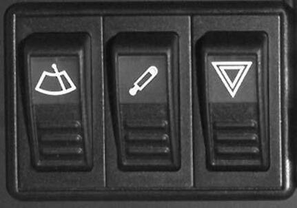
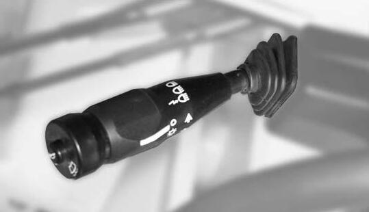
32Rotaryswitch–lights(parkinglightandlowbeam)........................................................................................................................3-11,3-27
33Tipswitch–washerpump..............................................................................................................................................................3-11,3-30
34Tipswitch–horn.............................................................................................................................................................................3-11,3-28
Controlpanel
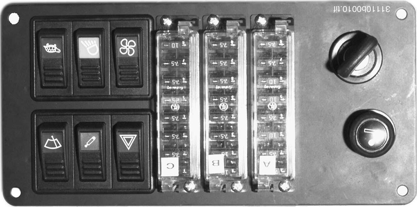
35WarningLight(red)–alternatorchargefunction.....................................................................................................................................3-13
36WarningLight(red)–coolanttemperature..............................................................................................................................................3-13
37WarningLight(yellow)–airfilter.............................................................................................................................................................3-14
38WarningLight(red)–hydraulicoiltemperature.......................................................................................................................................3-14
39WarningLight(red)–hydraulicoilfilter...................................................................................................................................................3-14
40WarningLight(red)–engineoilpressure................................................................................................................................................3-14
41WarningLight(red)–parkingbrake........................................................................................................................................................3-14
42WarningLight(green)–right/leftturnindicator.......................................................................................................................................3-15
43WarningLight(blue)–highbeam............................................................................................................................................................3-15
44Notassigned 45Hourmeter...............................................................................................................................................................................................3-15 46Fuellevelgauge......................................................................................................................................................................................3-15
49Notassigned Sideconsole 50FuseboxesA,BandC..............................................................................................................................................................................7-5 51Socket/cigarettelighter..............................................................................................................................................................................7-5
52Preheatingstartswitch.....................................................................................................................................................................3-8,3-16
53Rockerswitch–hazardwarningsystem.................................................................................................................................................3-28
54Tipswitch–lockforquickhitchfacility.....................................................................................................................................................3-50
55Rockerswitch–frontwiper......................................................................................................................................................................3-30
56Rockerswitch–fan.................................................................................................................................................................................3-29
57Rockerswitch–frontandrearworkinglights(option).............................................................................................................................3-27
58Rockerswitch–driverange....................................................................................................................................................................3-23
Telescopicunit:controllever
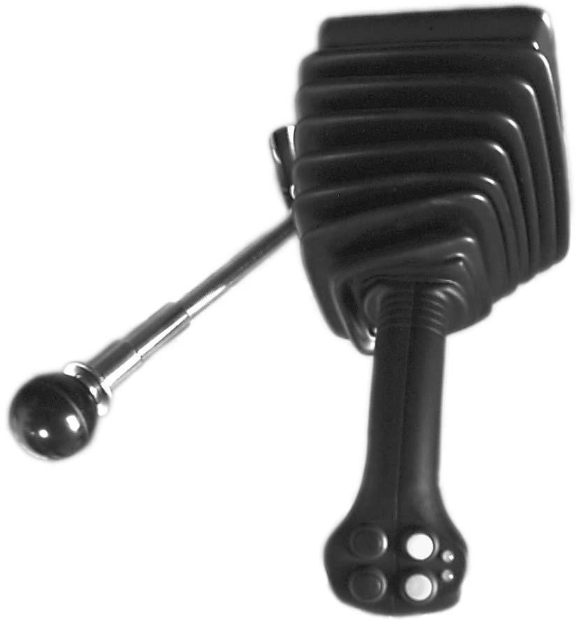
59Tipswitch(green)–forwardtravel...................................................................................................................................................3-8,3-24
60Tipswitch(yellow)–reversetravel...................................................................................................................................................3-8,3-24
61LED(green)–forwardtravel............................................................................................................................................................3-8,3-24
62LED(yellow)–reversetravel.................................................................................................... ........................................................3-8,3-24
63Tipswitch–extendtelescopicunit..........................................................................................................................................................3-53
64Tipswitch–retracttelescopicunit...........................................................................................................................................................3-53
Operation 3-4 AP0902 30864b0091.eps 30864b0060.eps 7 31 33 34 35 36 37 38 39 40 41 42 43 44 46 45
Fig.17:Multifunctionallever
Fig.18:Controllever
Fig.19:Controlpanel
Fig.20:Sideconsole
Page
Ref.no. Description
47Rockerswitch–rotatingbeacon(option)................................................................................................................................................3-28 48Rockerswitch–electricallyoperatedattachments(option).....................................................................................................................3-49
32 51 52 17 24 63 21 22 23 59 64 60 61 62 48 47 49 53 55 56 57 54 50 58 A B C
3.3Placingintoservice
3.3.1Safetyinstructions
• Onlyusethestepsandhandlesprovidedwhenenteringandleavingthecab
• Neverusethecontrolsormovablelinesandcablesashandles
• Neverjumponoroffamovingmachine
• Refertothecorrespondingloaddiagramsfortheloaderunitpalletforks
3.3.2Placingthemachineintoserviceforthefirsttime
Importantinformation
• Themachinemaybeplacedintoservicebyauthorizedpersonnelonly
• Theoperatingpersonnelmusthavereadandunderstoodthisoperator’smanualbefore placingthemachineintoservice
• Themachinemayonlybeusedingoodconditioninaccordancewithitsdesignateduse andtheinstructionssetoutintheoperator’smanual,andonlybypersonswhoarefully awareoftherisksinvolvedinoperatingthemachine
• Gothroughthe“Start-up”checklistinthefollowingsection
Running-inperiod
Operatethemachinecarefullyduringitsfirst100operatinghours.
Thefutureperformanceandservicelifeofthemachineareheavilydependentonthe observanceofthefollowingrecommendationsduringtherunning-inperiod.
• Donotoverloadthemachine,butatthesametimedonotdrivetoocautiouslyeither,as themachinewillneverreachtheproperoperatingtemperature
• Donotruntheengineathighspeedsforextendedperiods
• Increasetheloadgraduallywhilevaryingtheenginespeed
• StrictlyobservethemaintenanceschedulesintheAnnex
AP0902 3–5 Operation
3
Operation
Operation
3.3.3Checklists
Thechecklistsbelowareintendedtoassistyouincheckingandmonitoringthemachine before,duringandafteroperation.
Thesechecklistscannotclaimtobeexhaustive;theyaremerelyintendedasanaidfor youinfulfillingyourdutiesasaconscientiousoperator.
Thecheckingandmonitoringjobslistedbelowaredescribedingreaterdetailinsubsequentsections.
IftheanswertooneofthefollowingquestionsisNO,firstrectifythecauseofthefault beforecommencingorcontinuingwork.
Start-upchecklist
Checkthefollowingpointsbeforetakingthemachineintoserviceorstartingtheengine: No. Question ✔
1Sufficientfuelinthetank?(➠ 5-1)
2CoolantlevelOK?(➠ 5-10)
3Engineoillevelinorder?(➠ 5-7)
4Oillevelinhydraulicoiltankinorder?(➠ 5-16)
5BrakefluidlevelOK?(➠ 5-27)
6Waterlevelinwindscreenwashertankinorder?(➠ 3-30)
7Telescopiclinkagelubricated?(➠ 5-28)
8TireconditionOK?(➠ 5-30)
9Lights,signals,indicators,andwarninglightsOK? (➠ 3-27,3-28,3-13)
10Windows,mirrors,lightsandstepsclean?
11Istheattachmentonthetelescopiccorrectlyconnected?( ➠ 3-48)
12Istheenginecoverfirmlylocked?(➠ 3-38)
13Especiallyaftercleaning,maintenanceorrepairwork: Rags,toolsandotherlooseobjectsremoved?
14ApprovedSMVemblem,hazardwarninglightsinthemachine?(➠ 1-5)
15Seatpositionandrearviewmirrorcorrectlyadjusted?(➠ 3-16)
16Seatbeltfastened?(➠ 3-33)
3–6 AP0902
Operationchecklist
Afterstartingtheengineandduringoperation,checkandobservethefollowingpoints:
No. Question
1WarningLightsforengineoilpressure,coolantlevelandalternatorgoneout? (➠ 3-13)
2Brakingeffectsufficient?(➠ 3-21)
3Temperatureindicatorforenginecoolantinnormalrange?( ➠ 3-13)
4Isthesteeringworkingproperly?(➠ 3-21)
5Isanyonedangerouslyclosetothemachine?( ➠ 2-7)
6SafeloadindicatortestedandOK?(➠ 3-44)
Whentravellingonpublicroads,particularattentionshouldbepaidtothe followingpoints:
7Telescopicunitcompletelyretracted?(➠ 3-53)
8Bucketandattachmentsintransportposition?(➠ 3-20)
9Transportlocksinstalled?(➠ 3-20)
10Controlleverforliftandtilthydraulicsofthetelescopiclocked?(➠ 3-20)
Parkingchecklist
Checkandobservethefollowingpointswhenparkingthemachine:
No. Question ✔
1Attachmentsonthetelescopicunitloweredtotheground?(➠ 3-26,3-45)
2Parkingbrakeapplied?(➠ 3-10)
3Machinecablocked(especiallyifthemachinecannotbesupervised)?( ➠ 3-35)
Whenparkingonpublicroads:
4Machineadequatelysecured?(➠ 3-26)
Whenparkingonuphillanddownhillgradients:
5Machineadditionallysecuredwithchocksunderthewheelstopreventitfrom rollingaway?(➠ 3-26)
AP0902 3–7
Operation
✔
Operation
3.4Drivingthemachine
3.4.1Overviewofcontrols:
NOTE:
Thejoystickisinneutralwhenyoustarttheengine.Neutralisselectedwhenyou applytheparkingbrakeorturnofftheengine.Drivingdirectioncanbeselected onlyafterreleasingtheparkingbrake!

3–8 AP0902
Selectionofdrivingdirection/neutralpositionofdrive ☞ Selectionofdrivingdirection/neutralposition:
Preheatingstartswitch[52] NOTE: Theenginewillstartonlyifparkingbrake16/25 isapplied. DrivingdirectionselectorswitchFunction •
1 0 2 3 52 Fig.21:Preheatingstartswitch P Position Function Powerconsumer P NofunctionNone 0 InsertingorremovingignitionkeyNone 1 ON/driveposition ➥ Allfunctionsareoperational ➥ WarningLight19/41 comesonif parkingbrake16/25 isapplied 2 Preheatingengine(withcoldstartingat<0°C:10–15seconds) 3 Starttheengine ➥ Starterisactuated ➥ WarningLightsmustgoout 21 59
60 61 62 Function Operation Effect • Forward ☞ Pressgreentipswitch 59 ➥ GreenLED 61 comeson • Reverse ☞ Pressyellowtipswitch 60 ➥ YellowLED 62 comeson • Neutralposition ☞ Pressbothtipswitchesatthe sametime ➥ BothLEDsgoout
Fig.22:Drivingdirectionselectorswitch
Driverangeselector[58]Function
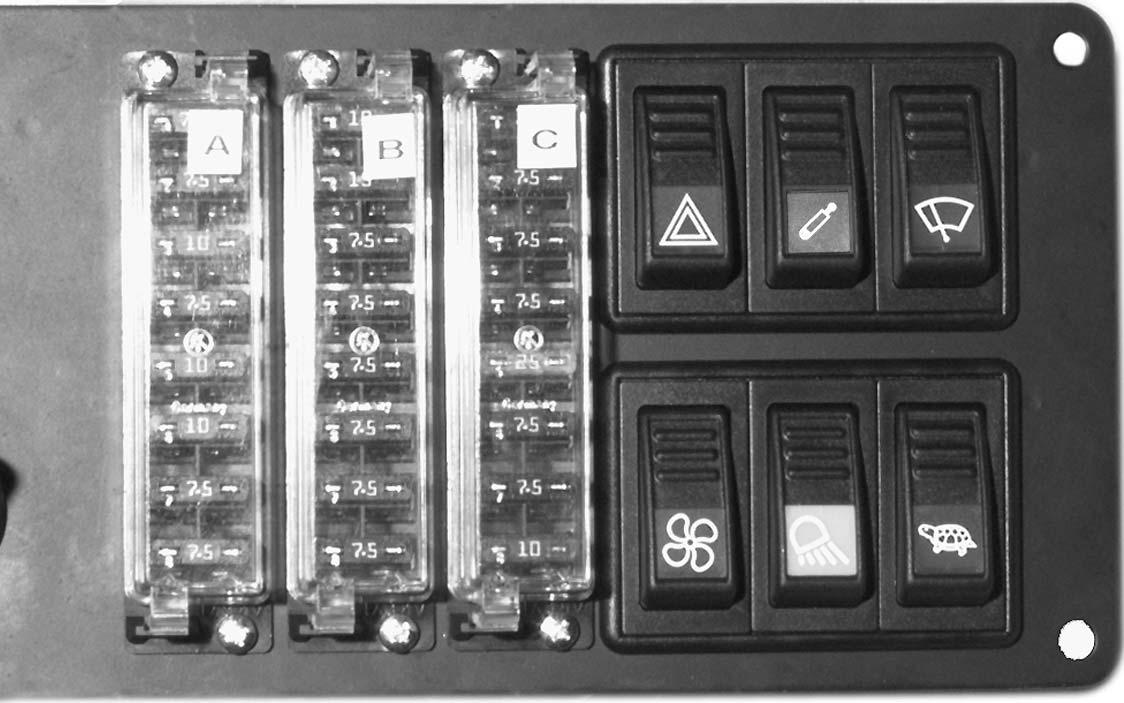
• Selectionofdriverangewithrockerswitch 58
Acceleratorpedal[6]
•
☞ Pressrockerswitch 58 in B (above) Long-haultransport,road travel
Theacceleratorpedal 6 controlsthedrivespeedasfollows:
• Presspedal
•
Brakeinchingpedal[3]Function
• Tobrakethemachineirrespectiveofthebrakingeffectofthedriveandthepositionof theacceleratorpedal 6
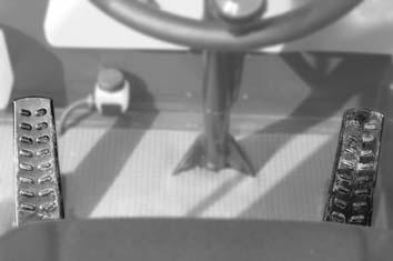
• Intheinchingrangeofthebrakepedal(pedalpressedinlightly),thepedalcanbeused likeacar’sclutch.Thedrivesystemissuppliedwithlesshydraulicoil,whichmeansthe entireengineoutputisavailabletotheworkhydraulics.Thisallowstheloadertoraise morerapidly
Braking
☞ Pressthebrakeinchingpedal 3 downwithforce
Inching
☞ Pressthebrakeinchingpedal 3 downlightly
AP0902 3–9
Operation
58 B A Driverange
Recommendedfor:
Fig.23:Driverangeswitch
Rockerswitch58
0–3mph (0–5km/h)
• Low
Heavywork
☞ Pressrockerswitch 58 in A (below)
0–12mph
High
(0–20km/h)
6
Fig.24:Acceleratorpedal
➥ Drivespeedisincreased
➥ Drivespeedisreduced
• Releasepedalslowly
Releasepedalfully ➥ Hydrostaticbraking
3
Fig.25:Brakeinchingpedal
NOTE:
Adrivinginterlockpreventsthemachinefromdrivingwiththeparkingbrake applied.
Theforward/reversedrivingdirectioncanbeselectedviatipswitches1859/and 18/60 andonlyiftheparkingbrakeisreleased.Applyingtheparkingbrakeautomaticallyinterruptsforward/reversedrivingdirection,whichissettoneutral(LEDs onjoystickgoesout).
• Preventsthemachinerollingaway
• Emergencybrakeincaseofservicebrakebreakdown
WARNING!
Usetheparkingbrake 25 insteadoftheservicebrakeonlyinanemergency, i.e.incaseofabreakdownoftheservicebrake.Thebrakelightsdonotlight up,andthemachinestopsabruptly,whichcanbehazardous
☞ Innormaloperation,onlyusebrakeinchingpedal 16/3 asaservicebrake
Topreventthemachinerollingaway
☞ Pulluplever 25 tothelastnotch
➥ WarningLight19/41 comeson
Toreleasetheparkingbrake
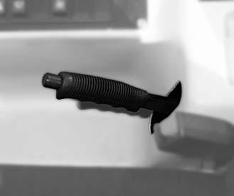
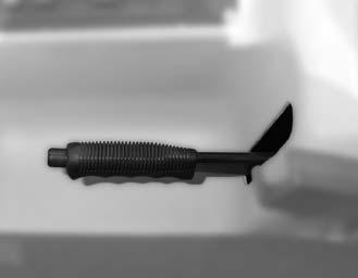
☞ Pulluplever 25 slightly
☞ Depressbutton a
☞ Movelever 25 allthewaydown
3–10 AP0902
Parkingbrake[25]Function
Operation
25
25
Fig.26:Parkingbrake
a
Fig.27:Applyingandreleasingtheparkingbrake
Tousetheparkingbrakeasemergencybrakewhendrivingthemachine
WARNING!
Operatingtheparkingbrake 25 whendrivingcausesthemachinedriveto disengage.Thiscausessuddendecelerationatfullspeed,whichcanbe hazardous.
☞ Usetheparkingbrake 25 asservicebrakeonlyincaseofemergency
☞ Beforeusingtheparkingbrake 25 reducedrivingspeedifpossible
☞ Pulluplever 25
Multifunctionallever[7]Function
• Switchontheturnindicatorswithlever 31
• Switchhighbeamonandoffwithlever 31
• Flashheadlightflasherwithlever 31
• Switchlights(parkinglightandlowbeam)onandoffwithrotaryswitch 32
• Switchonfrontwindowwasherpumpwithtipswitch 33
• Soundhornwithtipswitch 34
Switchesonhighbeamandheadlightflasherwithlever31
Lever31
☞ Centralposition 0
☞ Lowerposition I
☞ Raisetoposition II andholdinthis position
Turnindicationwithlever31
Lever31
☞ Pullupward
☞ Incenterposition
☞ Pullbackward
Effect
➥ Highbeamandheadlightflasher OFF
➥ Lowbeam ON
➥ Highbeam ON iflowbeamisswitched onwithrotaryswitch 32.WarningLight 43 comeson
➥ Headlightflasher ON,warninglight 43 comeson
Effect
➥ Leftturnindicatorsactuated,warning light 42 flashes
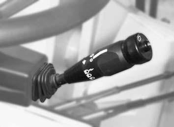
➥ None
➥ Rightturnindicatorsactuated,warning light 42 flashes
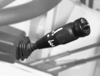
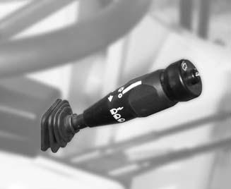
AP0902 3–11 Operation
31 7 32 33
34 7
Fig.28:Multifunctionallever
31 II 0 I
Fig.29:Switchingonhighbeamandheadlightflasher
31 L R
Fig.30:Turnindicators
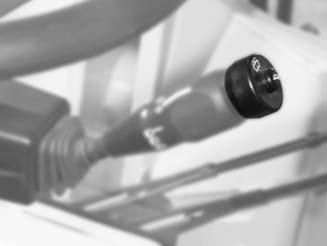
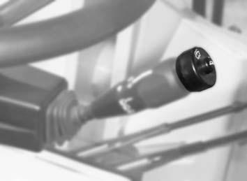
3–12 AP0902 Operation Actuatewasherpumpwithtipswitch33 Soundhornwithtipswitch34
33 Tipswitch33 Effect ☞ Slidetotheleftandhold ➥ Washerpump ON ☞ Release ➥ Washerpump OFF
Fig.31:Actuatingthewasherpump
34 Tipswitch34 Effect ☞ Press ➥ Horn ON ☞ Release ➥ Horn OFF
Fig.32:Actuatingthehorn
3.4.2WarningLights:overview
Unfoldpage3-4forabetteroverview!
35WarningLight(red)–alternatorchargefunction
Thewarninglightcomesonwhentheignitionisturnedonandgoesoutassoonasthe engineisrunning.
TheV-beltforthealternator,orthechargingcircuitofthealternatorisfaultyifthewarning lightcomesonwiththeenginerunning.Thebatteryisnotchargedanymore (➠ page 5-15
Important!
ThecoolantpumpnolongerrunsiftheV-beltisfaulty. Possibilityofengineoverheatingorbreakdown!
Ifwarninglight1935 comesonwiththeenginerunning:
☞ Switchofftheengineimmediatelyandrepairorhavethecauserepaired
36WarningLight(red)–coolanttemperature
Comesonifcoolanttemperatureistoohigh.Abuzzersoundsatthesametime.Thewarninglightandthebuzzergooutassoonasthecoolanttemperatureisbackintheacceptablerange.
WARNING!
Neveropenthecoolanttankandneverdraincoolantiftheengineiswarm, becausethecoolingsystemisunderhighpressure–
Dangerofburns!
☞ Waitatleast10minutesafterturningofftheengine!
☞ Wearprotectiveglovesandclothing
☞ Alwaysstartbyactuatingthesafetyvalveinthecapoftheexpansiontank. Todothis:Turnthecaptothefirstnotchandallowthepressuretoescape
Important!
Possibilityofenginebreakdownifwarninglight19/36 comesonwiththe enginerunning!
☞ Afterextremeworkload: Lettheenginerunatidleuntilthewarninglightgoesout
☞ Afternormalworkloadorifthewarninglightdoesnotgooutasdescribed above:
Turnofftheengineimmediately
☞ Checkandcorrectthecoolantlevel(➠ page5-10)
AP0902 3–13
Operation
Operation
37WarningLight(yellow)–airfilter
Indicatesairfiltercontamination.Inthiscase:
☞ Cleanorreplacetheairfilter(➠ page5-13)
38WarningLight(red)–hydraulicoiltemperature
Comesonifhydraulicoiltemperatureistoohigh.
Important!
Possibilityofhydraulicdamageassoonaswarninglight19/38 comeson!
☞ Reducetheloadontheworkanddrivehydraulics.Todothis:
•Stopthemachineinasuitableplace
•Movecontrollever16 /21 oftheloadertoneutralposition
•Setdriveswitchtoneutral–seeDrivingdirectionselectorswitchon page3-8
•Runtheengineatincreasedspeedsuntilwarninglight 19/38 goesout
39WarningLight(red)–hydraulicoilfilter
Indicatesanunacceptablyhighpressureinthehydraulicreturnlinetothetank.Inthis case:
☞ Replacethehydraulicoilreturnfilter(➠ page5-20)
Incoldweatherwarninglight19/39 maycomeonimmediatelywhentheengineisstarted. Thisisduetoincreasedoilviscosity.Inthiscase:
☞ Lettheenginerunatidlingspeedforabout2minutes
40WarningLight(red)–engineoilpressure
Comesoniftheengineoilpressureistoolow.Inthiscase:
☞ Stopthemachine
☞ Turnofftheengineimmediatelyandchecktheoillevel(➠ page5-7)
Thewarninglightcomesonwhentheignitionisturnedonandgoesoutassoonasthe engineisrunning.
41WarningLight(red)–parkingbrake
PComesonwhenparkingbrakelever16/25 isapplied. Theelectricdrivinginterlockpreventsdrivingthemachinewiththeparkingbrakeapplied.
3–14 AP0902
42WarningLight(green)–right/leftturnindicator Flashesintermittentlywhentheturnindicatorsareused(lever17/ 31)
43WarningLight(blue)–highbeam
Comesonifhighbeamisswitchedon,orduringheadlightflashing
44Notassigned
45Hourmeter
Countstheengineservicehourswiththeenginerunning
46Fuellevelgauge
AP0902 3–15
Operation
3.4.3Beforestartingtheengine
3.4.4Startingtheengine
General
Procedure
3
1 ☞ Runthroughthe“Start-up”checklistonpage3-6
☞ Adjustseatpositionandrearviewmirror CAUTION!
Allcontrolsmustbewithineasyreach.Youmustbeabletomovethebrakeand acceleratorpedalstotheirlimitpositions!
☞ Fasteningtheseatbelt
☞ Besurethat:
–Parkingbrake16/25 isapplied;and –Controllever16/21 and16/22 areinneutral
• Theenginewillstartonlyifparkingbrake16/25 isapplied
• Thestartercannotbeoperatediftheengineisalreadyrunning(startrepeatinterlock)
• Donotrunthestarterformorethan10seconds
• Waitforabout1minutetoletthebatteryrecoverbeforetryingagain
• Theenginecannotbestartedbytowingthemachine,becausethereisnodriving connectionbetweentheengineandgearboxwhentheengineisoff
☞ Afteryouhavecompletedthestartingpreparationsinaccordancewith3.4.3Before startingtheengine
• Inserttheignitionkeyintothepreheatingstartswitch33/52
• Turntheignitionkeytoposition“1”
• Checkwhetherthefollowingwarninglightscomeon:
•WarningLight 40 forengineoilpressure
•WarningLight 35 foralternatorchargefunction
•WarningLight 41 iftheparkingbrakeisapplied
•Duringthewarninglightcheck,warninglights 36, 37, 38 and 39 mustcomeonaswell,andthewarningbuzzermustsound
• Replacedefectivewarninglightsimmediately
• Presstheacceleratorpedal16/6 throughaboutaquarterofitstravel
• Turntheignitionkeytoposition“3”andholditinthispositionuntiltheenginestarts
• Releasetheignitionkey
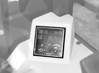
Whentheenginehasstarted...
☞ Checkthatthefollowingwarninglightshavegoneout:
• WarningLight34/35
• WarningLight34/40
• WarningLights34/36, 37, 38 and 39
☞ Runtheenginewarm
3–16 AP0902
Operation
1 0 2 3
52 35 40 41
Fig.33:Preheatingstartswitch
36 37 38 39 44 Operation
Fig.34:WarningLights
Startingattemperaturesbelow 32°F(0°C)
☞ Startingattemperaturesbelow32°F(0°C):
• Turntheignitionkeytoposition2andholditinthispositionforabout15seconds
• Presstheacceleratorpedal16/6 allthewaydown
• Turntheignitionkeytoposition“3”andholditinthispositionuntiltheenginestarts
• Releasetheignitionkey
Whentheenginerunssmoothly(increasedenginespeed):
• Releaseacceleratorpedal16/6
NOTE:
Ingeneral,abatterydeliverslessenergyincoldconditions.Asaresult,youmust besurethebatteryisalwayswellcharged.
...foracoldstartatoutsidetemperaturesbelow32°F(0°C):
☞ Lettheenginerunatincreasedidlingspeedforabout1minute
☞ Donotexceedtheaverageenginespeedfor10minutes, howeverdriveandworkhydraulicsmaybestartedgently.Donotextendorretractthe hydrauliccylinderstothelimitsifpossible
☞ Increasethedieselenginespeedandhydraulicforcesgradually
...foracoldstartatoutsidetemperaturesbelow50°F(10°C):
☞ Increasetheenginespeedslowly
☞ Donotruntheengineatfullloadforthefirst10minutes
AP0902 3–17
Operation
Operation
Enginepreheater(option)
Thisequipmentisforcold-startingattemperaturesbelow29°F(–5°C).
Thefollowing“enginepreheater”versionsareavailableforthemachine:
–Enginecoolantpreheater(option)
–Hydraulicoilpreheater(option)
–Coolantpreheater(option)andhydraulicoilpreheater(option)
Theoperationofthedifferentversionsisthesame.
Heatingelementsintheengineblockand/orinthehydraulicoiltankwarmuptheengine coolantcircuitand/orthehydraulicoilaccordingtothegravityprinciple(warmfluidrises andisreplacedbycoldfluid).Thecoolantortheoilcanonlybethoroughlywarmedupto servicetemperatureiftheenginepreheaterisconnectedoveralongerperiodoftime–preferablyovernight.
Connectingtheenginepreheater(option)
☞ Connectthe enginepreheater asfollows:
• Parkthemachineneara220Vsocket
• Firstconnectspecialcable A tomachinesocket B ontheservicepanelontheleft sideofthemachine,then
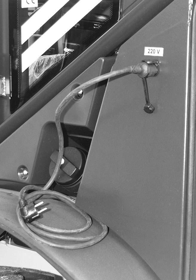
• Inserttheplugintothe220Vsocket
☞ Beforestartingtheengine:
• Pullouttheplugfromthe220Vsocket
• Unplugspecialcable A frommachinesocket B
NOTE:
Theenginepreheater(option)reducesengineemissionsduringthewarm-up phasebyupto50%,savingfuelatthesametime.
3–18 AP0902
A B
Fig.35:Enginepreheater(option)
Jump-startingtheengineSafetyinstructions
• Neverjump-starttheengineifthebatteryofthemachineisfrozenbecauseoftheriskof explosion!
• Themachinemustnottouchthejump-startingmachinewhenconnectedwithjumper cablesbecauseoftheriskofsparking!
• Theexternalpowersourcemustdeliveraratedvoltageof12V;highersupplyvoltages willdamagetheelectricalsystemofthemachine!
• Useonlyjumpercablesthatareingoodcondition!
• Thejumpercableconnectedtothepositive(+ )terminalofthestartingbatterymust nevercontactmetalmachinepartsbecauseoftheriskofshortacircuit!
• Routethejumpercablessotheycannotcatchonrotatingcomponentsintheengine compartment!
Proceedasfollows:
• Drivethejump-startingmachinecloseenoughtothemachinesothatthejumper cablescanreachtoconnectthetwobatteries.
• Starttheengineofthejump-startingmachine.
• Firstconnectoneendoftheredjumpercable(+ )tothe(+ )terminalofthe dischargedbattery,thencliptheotherendtothe(+ )terminalofthestartingbattery.
• Connectoneendoftheblackjumpercable(–)tothe(–)terminalofthestarting battery.
• Cliptheotherendoftheblackjumpercable(–)ontoasolidmetalcomponent connectedtotheengineblockorontotheengineblockitself.Donotconnectittothe negativeterminalofthedischargedbattery,becauseexplosivegasfromthebattery mayigniteifsparksoccur!
• Starttheengineofthemachinewiththedischargedbattery
Oncetheenginehasstarted:
☞ Withtheenginerunning,disconnectthejumpercablesinexactlythereversesequence (firstremove(–)terminal,then(+ )terminal)–thispreventssparkinginthevicinityof thebattery!
AP0902 3–19
Operation
Operation
3.4.5Beforedrivingthemachine
Beforedrivingthemachine:
• Checkthefunctionof:
•Brakes
•Steeringand
•Lighting
• Dumpoutthebucket
• Adjustthebuckettotransportposition.Todothis:
•Retractthetelescopicunitcompletely
•Tiltthefrontbuckettotherear(36/B)and
•Raisethetelescopicunitsothatbothredmarks D ontheliftframeandthe bulkheadarealigned
NOTE:
Intransportposition,tworedmarks D ontheliftframeandonthebulkheadare aligned(figure37).Thesemarkingsarevisiblefromtheoperator'scab. Withbothmarks D aligned,transportgroundclearanceamountstoatleast9inches (230mm)(36/C),withstandardbucketandstandardtires(12.5-20).
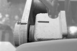
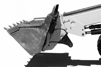
• Securethecontrolleverforthetelescopicunit 21 againstunintentionaloperation.To dothis:
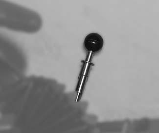
Pushcontrollever 21 downinneutralposition
➥Thecontrolleverislockedinthisposition,itcannotbemoved
• Securethecontrolleverforthe3rdcontrolcircuit/attachments 22 againstunintentionaloperation.Todothis:
•Turnsafetysleeve 23 clockwiseuntilitispulleddownbyspringaction.
•Letcontrollever 22 lockintoplaceincentralposition.
➥Thecontrolleverislockedinthispositionandcannotbemoved.Thelockcanonly bereleasedbyliftingthesafetysleeve
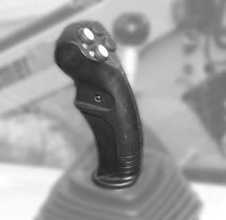
3–20 AP0902
C B
Fig.36:Drivingonpublicroads
D
Fig.37:Marksfortransportposition
21
Fig.38:Securingthecontrolleverforthetelescopicunit
22 23
Fig.39:Securingthecontrolleverfortheattachments
NOTE:
Thesteeringsystemisonlyoperationalwhentheengineisrunning! Intheeventofafailureofthedieselengineorofthehydraulicsteeringpump(e.g. failureofthepumpdrive),themachinecanstillbesteered(emergencysteering feature).
WARNING!
Incaseoffailureofsteeringpumpordrive: Turningthesteeringwheelrequiresgreateffort!Takethisintoaccount especiallywhentowingthemachine!
☞ Adapttowingspeedtothealteredsteeringbehavior!
☞ Useatowingrod!
☞ Functionalcheck:Movethesteeringwheeltotheleftandright Wheelsynchronizationposition Important!
Carefullysteeringthefrontandrearwheelstotheirlimitsautomaticallysynchronizesthesteeringsystemofthemachine.
Ifyounoticefromthedrivingcharacteristicsofthemachinethatthewheelsofbothaxles arenotrunninginexactlythecorrecttrack:
☞ Driveatlowspeed,turningthesteeringwheelslowlytotheleftandrighttothelimit,and trytokeeponturningthesteeringwheelbrieflyinbothfinalpositions
☞ Slowlyturnbackthesteeringwheeltostraight-aheadposition
☞ Contactyourdealerifthisdoesnotsynchronizethewheels
AP0902 3–21
Operation
Inspectionofimportantfunctional units
Steering
3.4.6Driving
Servicebrake
WARNING!
Thebrakelightsattherearofthemachinedonotlightupwhenthe
•Parkingbrakeisapplied
•Machineisbrakedwithitshydrostaticbrakingeffect
☞ Whendrivingonpublicroadsandduringworkoperation,especiallyfor abruptbrakemaneuvers,usethebrakeinchingpedal16/3 tobrakethe machine.Onlythiscausesthebrakelightstolightup.
Dirtaccumulationintheareaofthebrakepedalcanresultinbrake malfunctions–
☞ Keepthebrakeinchingpedal16/3 clean!
☞ Checktheservicebrakeactionasfollows:
• Beforedrivingmachine,pressdownthebrakeinchingpedal16/3 tocheckwhether
•Afteramaximumofhalfthepedaltravelthereisafirmresistancetobefelt
•Brakelightscomeonifthebrakepedalispresseddown
• Aftermovingmachine,checkintherearviewmirrorthatnoonewillbehinderedbya brakemaneuver
• Checkthebrakeactionatlowspeed
NOTE:
Themachinecanbemovedonlyafterreleasingparkingbrake16/25.
☞ Afterstartingtheengine,proceedasfollows:
• Selectdrivingdirectionwithtipswitch18/59 or18/60
• Releaseparkingbrake16/25
➥WarningLight19/41 goesout
• Graduallydepressacceleratorpedal16/6
➥Machinemovesoff
• Testthebrakesatlowspeed
3–22 AP0902
Operation
3.4.7Driveranges
Selectingdriverange
Themachinehas2driveranges.
☞ Stopthemachinewithbrakeinchingpedal 16/3
☞ Pressbothtipswitches 18/59 and 18/60 atthesametime
☞ Selectionofdriverangewithrockerswitch 58
WARNING!
Donotswitchfromhightolowdriverangeatfullspeed–
➥ Machinedrivesystemalsomaybedamaged!
☞ Switchdriverangeswiththemachinedrivingatlowspeedonly
forworkrequiringprecisespeedadjustment,e.g.rotarybroomapplications
•
☞
AP0902 3–23
Operation
58 B A Driverange Rockerswitch58
Fig.40:Selectionofdriverangewithrockerswitch
Recommendedfor: • Low 3mph 0–5km/h ☞ Pressrockerswitch 58 in A (below) Especiallyforshortloading/unloading cycles,truckloading,e.g.,ontoalorry,and
High 12mph 0–20km/h
Pressrockerswitch 58 in B (above) Long-haultransport,roadtravel
Operation
Changingdirection
WARNING!
Changingdirectionathighspeedandhighenginespeedscausesthemachine tostopabruptly–
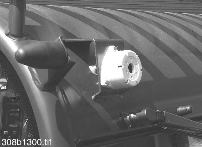
➥ Machinedrivesystemalsomaybedamaged!
☞ Switchdirectiononlywhenmachineusstopped.
☞ Stopthemachine.Takeyourfootoffacceleratorpedal16/6
☞ Selectnewdrivingdirectionasfollows:
Function
•
Backupalarm(option)
•
•
NOTE:
Thejoystickisinneutralwhenyoustarttheengine.Neutralisselectedafterapplyingparkingbrake16/25 orswitchingofftheengine.Drivingdirectioncanbe selectedonlyafterreleasingtheparkingbrake!
DANGER!
Whenbackingupwiththemachine: Accidenthazard!
☞ Makesurethatnobodyiswithintheareaofdangerofthemachinewhen changingthedrivingdirection!
☞ Donotrelyexclusivelyonthebackupwarningsystem(option)!
Thebackupalarm A,isfittedtothereartopleftofthecab.Thealarmsoundswhen shiftingintoreverse.Thesoundlevelis: 103dB(A)atadistanceof40inches(1m),andatafrequencyof2800Hz.
3–24 AP0902
21 59 60 61 62
Fig.41:Drivingdirectionselectorswitch
Operation Effect
☞ Pressthegreentipswitch 59 ➥ GreenLED 61
Forward
comeson
☞ Pressyellowtipswitch 60 ➥ YellowLED 62
Reverse
comeson
Neutralposition ☞ Pressbothtipswitchesatthe sametime ➥ BothLEDsgoout A
Fig.42:Backupalarm(option)
3.4.8Differentiallock
NOTE:
Adifferentiallockneutralizesthecompensatingeffectofthedifferential,i.e.tractionisdistributedevenlytothefrontandrearwheels.Boththefrontandrearaxles ofthemachinearefittedwithself-lockingdifferentials.Thelockingvalueis40%for eachaxle.Thedifferentialsarelockedautomatically.Thedifferentiallockcannot beengagedordisengagedbytheoperator!Ifawheellosescontactwiththe ground,thedifferentiallockontherespectiveaxleisnolongereffective!
3.4.9Stoppingthemachine
☞ Proceedasfollows:
• Throttlebacktheengine:Takeyourfootoffacceleratorpedal16/6
• Stopthemachinewithservicebrake16/3
• Movedrivelevertoneutral–see Drivingdirectionselectorswitch onpage3-8
• Applytheparkingbrake.Todothis: Pulluplever16/25 tothelastnotch
➥WarningLight19/41 comeson
AP0902 3–25
Operation
3.4.10Parkingthemachine
WARNING!
Machinesparkedonslopesmayrollaway.
☞ Usetheparkingbraketoparkthemachinesafelyandtopreventitrolling away!
SeeSection3.4.9„Stoppingthemachine”
☞ Additionallysecurethemachinebyplacingchocksunderthedownhillsides ofthewheels!
Donotparkthemachinewiththeloadliftedorthetelescopicunitextended–Accidenthazard!
☞ Beforeleavingthecab,retractthetelescopicunitcompletelyandlowerthe loadtotheground!
☞ Proceedasfollows:
• Stopthemachine
• Movedriveswitchtoneutral.Todothis: Pressdownswitches 59 and 60 atthesametime(bothLEDs 61and62 goout)
• Applytheparkingbrakepermanently–see Section3.4.9„Stoppingthemachine”
• Retractthetelescopicunit.Todothis: Presstipswitch 64 untilthetelescopicunitiscompletelyretracted
• Lowerthetelescopicunit.Todothis: Pushcontrollever 21 forward,outofneutral( C)

Afteroperationatfullpower:
• Allowtheenginetoidleandwithoutloadforawhilesothatthetemperaturecan stabilize
• Cutofftheengine.Todothis: Turntheignitionkeytoposition“0”
• Removetheignitionkey
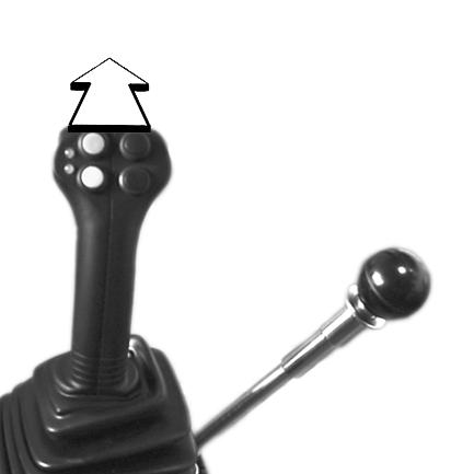
• Lockthedoorsoftheoperator’scompartmentafterleavingthecab
Onuphillanddownhillgradients:
• Additionallysecurethemachinebyplacingchocksunderthedownhillsidesofthe wheels!
3–26 AP0902
Operation
21 59 60 62 61 C
Fig.43:Movethedriveswitchtoneutral
21 63 64
Fig.44:Retractingandloweringthetelescopicunit
3.4.11Lightsystem
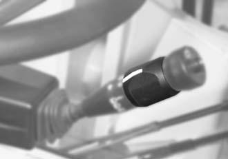
NOTE:
Onlytheparkinglightstayslitiftheignitionisswitchedoff(withlowbeamswitched

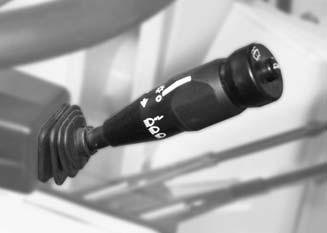
AP0902 3–27 Operation
on)–keyinpreheatingstartswitch20/52 inposition 0!
☞ Donotusetheworkinglightsfortravelonpublicroads,andinworkoperationonlyifnootherpersonsaretemporarilyblind! 32
Parkinglights ON ☞ Turnrotaryswitch 32 toposition I ➥ WarningLight19/43comesonwith highbeamswitchedon OFF ☞ Turnrotaryswitch 32 toposition 0 ➥ Highbeamandwarninglight19/43 go out Lowbeam ON ☞ Turnrotaryswitch 32 toposition II ➥ WarningLight19/43comesonwith highbeamswitchedon OFF ☞ Turnrotaryswitch 32 toposition 0 ➥ Highbeamandwarninglight19/43 go out 31
WARNING! Theworkinglightsmaytemporarilyblindmotoristsonpublicroads.
Fig.45:Lightsystem:switches
II 0 I Highbeam ON ☞ Withlowbeamswitchedon,move leverdownwarduntilitlocksin position I ➥ WarningLight19/43 comeson OFF ☞ Movelever 31 uptoposition 0 ➥ Highbeamandwarninglight19/43 go out Headlightflasher ON ☞ Pushlever 31 uptoposition II ➥ WarningLight19/43 comeson
Fig.46:Switchingonhighbeamandheadlightflasher
A B 57 Workinglight(option) ON ☞ Pressrockerswitch 57 downwardsin A (down) ➥ WarningLightinrockerswitch 57 comeson OFF ☞ Pressrockerswitch 57 downwardsin B (above) ➥ WarningLightinrockerswitch 57 goesout Interiorlight ON ☞ Pressinteriorlight16/ 9 OFF ☞ Pressinteriorlight16/ 9 downasecondtime
Fig.47:Switchforworkinglight
3.4.12Signallingsystem

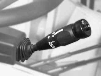
Important!

3–28 AP0902
Operation
Checkthefrontandrearindicatorsimmediately
A B 53 Hazardwarningsystem ON ☞ Pressrockerswitch 53
A (down) ➥ WarningLightinrocker switch 53 flashes OFF ☞ Pressrockerswitch 53 downwardsin B (above) ➥ WarningLightinrocker switch 53 goesout Fig.49:Turnindicators 31 L R Turnindicators LEFT ☞ Pushlever 31 forward ➥ WarningLight19/42 flashes RIGHT ☞ Pulllever 31 totherear ➥ WarningLight19/42 goes out
A B 47 Rotatingbeacon(option) ON ☞ Pressrockerswitch 47 in A (below) ➥ WarningLightinrocker switch 47 flashes OFF ☞ Pressrockerswitch 47 in B (above) ➥ WarningLightinrocker switch 47 goesout
Theturnindicatorsystemisnotfunctioningproperlyifwarninglight19/ 42 flashesabouttwiceasfastasnormally! ☞
Fig.48:Signalingsystem:switches
downwardsin
Fig.50:Switchforrotatingbeacon
3.4.13Cabheatingandventilation
Theheaterofthemachinecanbesettotwooperatingconditions:
•Ventilation
•Heating
Theflowofairisdirectedtothewindscreenviaadefrosterventandtotheoperator compartmentviaafootvent16/19 Thefootventcanbeclosedanddirectedseparately.

Ventilation,freshair
1stfanlevel ☞ Pressrockerswitch 56 downin A (below)byonestep
2ndfanlevel ☞ Pressrockerswitch 56 downin A (below)bytwosteps

FanOFF ☞ Pressrockerswitch 56 allthewaydownin B (above)
Heating
Colder ☞ Slidelever 18 toposition B
Warmer ☞ Slidelever 18 toposition A
AP0902 3–29 Operation
A B
Fig.51:Fanswitch
56
A
B 18
Fig.52:Heatingadjustment
NOTE: Fillwithcleantapwateronly!Addasuitablecleaningagentifrequired.Inwinter: Addantifreezeforwashersystemstothewater.Refertotheinstructionsforusing theantifreeze,whichgiveinformationaboutconcentrations.
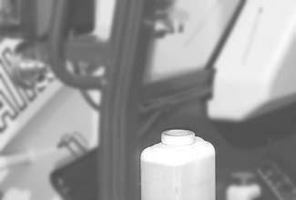
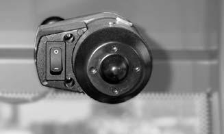
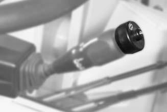

3–30 AP0902
Tankforwashersystem2
Operation 3.4.14Windowwashsystem
A B 55
Frontwiper ON ☞ Pressrockerswitch 55 in A (below) OFF ☞ Pressrockerswitch 55 in B (above) 33
Fig.53:Frontwiper:switch
A B Washerpumpforfrontandrearwindow ON ☞ Presstipswitch 33 toposition A OFF ☞ Releasetipswitch
B
Fig.54:Washerpumptipswitch
33 (
)
10 Rearwiper ON ☞ Pressrockerswitch 10 toposition I OFF ☞ Pressrockerswitch 10 toposition 0 2
Fig.55:Rearwiper:rockerswitch
Fig.56:Tankforwashersystem
3.4.15Seatadjustment
WARNING!
Neverchangetheseatpositionwhendrivingorworkingtoavoidandaccident.
☞ Adjusttheseatbeforemovingthemachine
Theseatcanbesettothefollowingpositions:
• Weightsetting a withweightindicator b
• Heightsetting c
• Armrestangle d
• Backrestsetting(dependingonversion) e
• Fore-and-aftsetting f
Weightsetting
Heightsetting
Important!
Adjusttheseatsuspensioncorrectlytoensurecomfort.Uselever a toadjustthe seatsuspensiontotheoperator'sweight.Theweightindicator b showstheset operatorweightinkg.
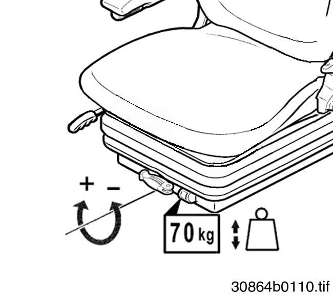
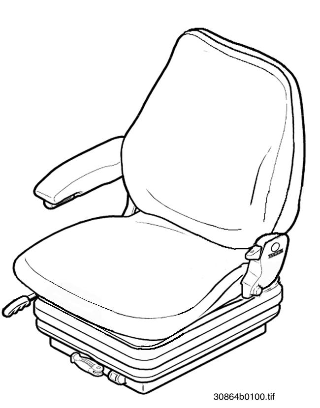
☞ Sitdownontheoperator’sseat
Toadjusttoahigheroperatorweight:
☞ Turnlever a clockwise
Toadjusttoaloweroperatorweight:
☞ Turnlever a counterclockwise
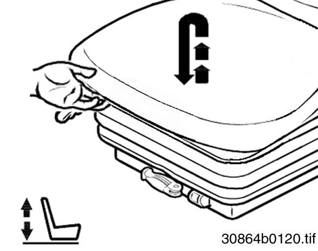
Upwards:
☞ Raiseseatasrequireduntilitengageswithanaudibleclick
Downwards:
☞ Raiseseatasfaraspossibleand
☞ Lowerseattobottomposition
AP0902 3–31 Operation
b c a f d e
Fig.57:Seatadjustment
a b
Fig.58:Weightadjustment
c
Fig.59:Heightsetting
Operation
Armrestsetting
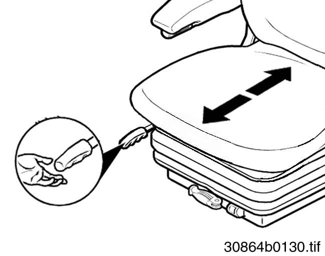
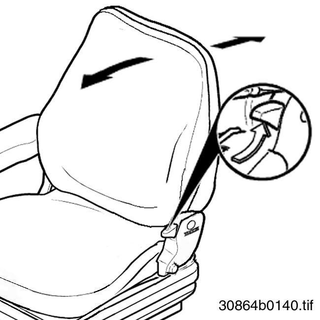
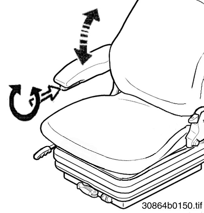
Thearmrestcanbefoldedbackasrequired.Setthearmrestasfollows:
Upwards:
☞ Turnhandwheel d clockwiseasrequired
Downwards:
☞ Turnhandwheel d counterclockwiseasrequired
Backrestsetting
☞ Sitdownontheoperator’sseat
☞ Pulllever e upwardsandatthesametime
☞ Leanbacktopushthebackrestintotherequiredposition
☞ Letlever e lockintoplace
Fore-and-aftsetting
☞ Sitdownontheoperator’sseat
☞ Pulllever f upwardsandatthesametime
☞ Movetheoperator’sseatforwardorbackward
3–32 AP0902
Fig.60:Armrestsetting
d
e
Fig.61:Backrestsetting
f
Fig.62:Fore-and-aftsetting
3.4.16Seatbelt
WARNING!
Donotoperatemachinewiththeseatbeltunbuckledtoavoidpersonalinjury.
☞ Buckleupbeforemovingorusingthemachine!
•Seatbeltmustnotbetwisted!
•Seatbeltmustrunoverthehips–notoverstomach–andmustalways beappliedtightly!
•Donotplaceseatbeltoverhardedgedorfragileitems(tools,glasses, pen)carriedinsideyourclothes!
•Neverbuckleup2persons(children!)withasingleseatbelt!
•Checkseatbeltsregularly.Havedamagedpartsimmediatelyreplaced!
•Alwayskeepseatbeltclean,asdirtmayimpairproperfunctioning!
•Seatbeltbucklemustnotbeobstructedotherwisethebucklelatchcannotlockintoplace!
WARNING!
Afteranaccidentthebeltstrapmaybestretched,andisnolongerserviceable. Inanaccident,theseatbeltwillnotprovideadequateprotection!
☞ Replacetheseatbeltafteranaccident
☞ Havefasteningpointsandseatfixturecheckedforloadingcapacity!
Theseatbelt 29 isdesignedforthedriver'ssafetyduringworkonconstructionsitesand duringroadtravel.
Tofastenseatbelt29
☞ Beforestarting,fastenseatbelt 29 asfollows:
• Holdbeltonthebucklelatch A andrunitslowlyandsteadilyoverthehipstothe buckle B
• Insertbucklelatch A intothebuckle B untilitengagesaudibly( pulltest )
• Tightenseatbeltbypullingatitsend
➥Theseatbeltmustalwaysbetightlyinplaceoverthehips!
AP0902 3–33 Operation
30763b0007.eps
29 B A
Fig.63:Fasteningtheseatbelt
Operation
Tounfastenseatbelt29:
☞ Unfastenseatbelt 29 asfollows:
• Holdtheseatbelt
• Pressredbutton C onthebuckle B
➥Thelatch A isreleasedfromthebuckle B byspringpressure
• Slowlyreturntheseatbelttheretractor(option)
Longer/shorterlapbeltsetting29:
☞ Lengthenthelapbeltasfollows:
• Holdthebucklelatchatarightangletotheseatbeltandpulltheseatbelttothe requiredlength–seeFig.65
☞ Toshortenthelapbelt,justpullonthefreeend D ofthebelt–seeFig.65
NOTE:
Whenpulledslowly,theautomaticseatbelt(option)offersfullfreedomofmovement.Itlockshoweverduringabruptbraking. Theautomaticseatbelt(option)mayalsolockwhenpassingthroughpotholesor uneventerrain.
3–34 AP0902
30763b0006.eps
29 B A C
Fig.64:Tounfastenseatbelt
30763b0005.eps
A D
Fig.65:Longer/shorterseatbeltsetting
3.4.17Driver'sdoorandsidewindow
Accessto/exitfromthecabispossiblethroughthedriver'sdoor(left).Incaseof emergencyhowever,thesidewindowontherightmaybeusedasemergencyexit.
Openingfromoutside:
• Pressdoorbutton a
Lockdoor:
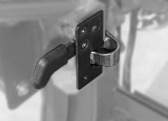
• Turnignitionkey b indoorlocktotheright
Unlockdoor:
• Turnignitionkey b indoorlocktotheleft
Openingfrominside:
• Pulllever 1 up
Driver'sdoorin“open”positionwiththedoorarrester
☞ Presstheoperator'sdooragainstthedoorholder16/12 untilitengages
NOTE: Greasethedoorholderatregularintervals(min.every600servicehours)!
Unlockingthedoorarrester
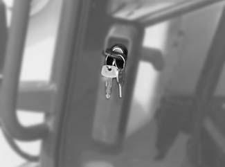
☞ Pressthereleasebuttoninthecab(16/12)
➥ Doorisreleasedbyspringaction
AP0902 3–35
Operation
Driver'sdoor
b a
Fig.66:Doorlockontheoutside
1
Fig.67:Doorlockontheinside
Operation
SidewindowNormaloperation
Lock
• Turnlever 16 downward
Unlock
• Turnlever 16 upward
Openingthehingedsidewindow
• Turnlever 16 upward
• Pushlever 16 horizontallytowardstheoutside
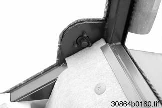
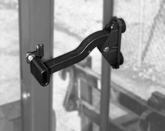
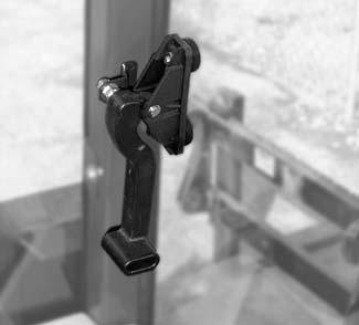
• Tofixthewindowinitslimitposition: Pushtheendoflever a downwardinguide b
Fullyopeningthesidewindow
☞ Turnlever 16 upward
☞ Pushlever 16 horizontallytowardstheoutside
☞ Fullyopenthewindowasfollows: Pulltheendoflever a totherear,outofguide b
Sidewindowin“open”positionwithdoorholder 16/12
☞ Openthesidewindowcompletelyandpushagainstdoorholder16/12 untilthedoor locksintoplace
NOTE: Greasethedoorholderatregularintervals(min.every600servicehours)!
Unlockingthedoorholder 16/12
☞ Pressbutton16/12 inthecabattherightoractuatetheleveroutsidethemachine
➥ Sidewindowisreleasedbyspringaction
3–36 AP0902
16
Fig.68:Locking/unlockingthesidewindow
16 b a
Fig.69:Openingthehingedsidewindow
16 b a
Fig.70:Fullyopeningthesidewindow
12
Fig.71:Fullyopeningthesidewindow
Emergencyexit
Incaseofemergency,thesidewindowmaybeusedasaccessto/exitfromthecab.
WARNING!
Toavoidpersonalinjury,donotusethesidewindowasanaccessorexit exceptincaseofanemergency.Therightsideofthemachinedoesnothave footholdsorhandlesthatensureasafeaccess/exit.Moreover,theside windowcannotbeheldin“open”positioniflockinglever69/16 isliftedoutof guide69/b –
Dangerofpersonalinjury!
☞ Donotusethesidewindowasaccessorexitexceptincaseofemergency!
☞ Beforetakingupnormaloperationagain,besurethattheendoflever69/a isengagedinguide69/b
☞ Toopenthesidewindowcompletely:
• Pushendoflever69/a upwardsinguide69/ b
• Pullendoflever69/a gentlyoutofguide69/b
AP0902 3–37
Operation
Operation
3.4.18Othercontrols
Fueltank
Unlocking:
• Turnthekeytotheright
Closing:
• Turnthekeytotheleft
Enginecover
Theenginecovercanonlybeopenedbykey.
Unlocking:
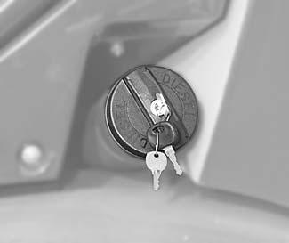
• Turnthekeytotheright
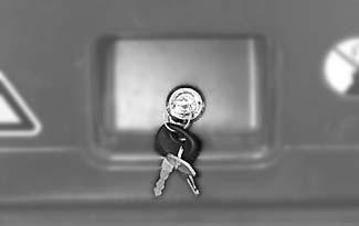
• Pulltheenginecoverupwards
Closing:
• Presstheenginecoverfirmlydown
• Turnthekeytotheleftandremoveitfromthelock
3–38 AP0902
Fig.72:Fillercaplock
Fig.73:Enginecoverlock
3.4.19Towingandtransportingthemachine
Safetyinstructions
• Themachinemayonlybetowedusingsuitabletowingequipment(towingbarorcable) andsuitabletowingfacilities,suchasatowingcoupling,hooksandeyes!
• Driveoffslowly!Besurenooneisdangerouslyclosetothetowingbar.
• Themachinemayonlybetowedwithacableiftheservicebrakesandsteeringarefully operational!
Whenloadingandtransportingthemachine:
• Thetransportmachinemustbeofadequatesize–refertosection Specifications forthe dimensionsofthemachine!
• Removeanymud,snoworicefromthetyressothatthemachinecansafelybedriven ontotheramps
• Securethemachineagainstunintentionalmovement!
• Beforetransportingthemachinethrough heavyrain:Closetheoutletoftheexhaust silencerwithasimplecaporsuitableadhesivetape
AP0902 3–39
Operation
WARNING!
Turningthesteeringwheelrequiresgreatereffortifthedieselenginebreaks down.Takethisintoaccount,especiallywhentowingthemachine!
☞ Useatowingrod! Important!
Thehydrostaticdrivemaybedamagedifthemachineistowedinthis condition!
☞ Switchofftheengine!
☞ Short-circuitthehydrauliccircuitbeforetowing(seebelow)
☞ Donottowthemachineformorethan100yards(100meters)anddonot towitfasterthan2-3mph(3–4km/h)!
☞ Towthemachineasfollows:
• Movedrivelevertoneutral–see Drivingdirectionselectorswitch onpage3-8
• Applytheparkingbrake(➠ page3-10)
• Switchofftheengine
• Attachanadequatelysizedtowingrodtothetowingfacilities
☞ Changeoverthevalvesonhydraulicpump A .Todothis:
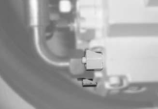
• Depressbuttons B
NOTE:
TheHPvalvechangeoverisautomaticallyreversedwhenthemachineisplaced backintoservice,assoonastheengineisstarted.
3–40 AP0902
Operation Towing
A B
Fig.74:Hydraulicpumpwhentowingthemachine
WARNING!
Toavoidinjury,themachinemustbeloadedandtransportedproperly:
☞ Itisessentialthatyoureadthesafetyinstructionsatthebeginningofthis chapterandfollowthem!
☞ Loadasfollows:
• Securethetransportmachinewithchockstopreventitfromrolling
• Attachtherampssothattheaccessangleisassmallaspossible,andensurethat theycannotslip
• Ensurethattheloadingareaisclearandaccesstoitisnotobstructed.
• Ensurethattherampsandthewheelsofthewheelloaderarefreeofoil,grease andice
• Starttheengineofthewheelloader
• Raisethefrontbucketenoughsothatitwillnottouchtheramps
• Carefullydrivethewheelloaderontothetransportmachine
• Movedrivelevertoneutral–see Drivingdirectionselectorswitch onpage3-8
• Applytheparkingbrakeofthewheelloader
• Lowerthebuckettotheloadingareawiththetelescopicunitretracted
• Ensurethattheauthorizedmaximumheightisnotexceeded
• Cutofftheengineofthewheelloader
• Securealltyresofthewheelloaderwithchocksinfrontof,behindandatthesidesof eachwheel
• Securelylashthewheelloaderontotheloadingareausingstrapsandchainsof adequatesizeatthelashingpointsprovided–seesection1.2 Machine:Overview on page1-2
• Beforetransportingthemachinethroughheavyrain: Closetheoutletoftheexhaustsilencerwithasimplecaporsuitableadhesivetape
• Makecertainthatthedriverofthetransportmachineknowstheoverallheightofhis machinebeforedeparture!
AP0902 3–41
Operation
Loadingandtransportingthe machine:
3.5Workingwiththemachine
3.5.1Generalsafetyinstructions
• Neverlowertheextendedtelescopicunitfromahighposition,becauseofthechanceof tipping!Retractthetelescopicunitbeforeloweringit!
• Exerciseextremecautioninoff-roadoperation: Workonsolidgroundwheneverpossible!
• Neverdriveuptotheedgeofapitfromoutside,becauseofthechanceofcave-in!
• Neverunderminethefoundationsofwalls,becauseofthechanceofcollapse!
• Operationofthemachinebyunauthorizedpersonsisprohibited!
• Whenexcavating,lookoutforhigh-voltage cables,undergroundcables,gasandwater pipes!
• Whenusingliftingaccessoriessuchaspalletforks,complywiththeloaddiagramsfor thismachine
• Thehydraulicsystemofthemachineremainspressurizedevenwhentheengineisnot running!Relievethepressureinthesectionsofthesystemandhydrauliclinesthatare tobeopenedbeforestartingsetuporrepairwork,e.g.fitting/removinganattachment withhydraulicfunctions–see Section3.5.6„Relievingpressurethequickcouplerson thetelescopicunit”
3.5.2Loaddiagram
Observetherelevantloaddiagramwhenusingpalletforkswithforkarmsonthetelescopic.Thisdiagramspecifiesmaximumloadontheforkarms–seesection1.8 Safety signsandsymbols onpage1-8.Themaximumloadvariesaccordingtothedistancefrom theloadcenter.
NOTE:
Theloaddiagramsonthefrontwindowarevalidonlyforapplicationswithpallet forks.Observethespecificloaddiagramsofotherattachmentsused,e.g.rotaryjib boom!
3–42 AP0902 Operation 3
Overview
WARNING!
Thesafeloadindicatorhasbeenadjustedforindustrialapplication(S=1.25). Donotrelyonthesafeloadindicatorwhenworkingoff-road.
☞ Workinroughterrainwithevenmorecarethanusual!Adaptyourdrive speedandloadstotheterrain.Refertotheloaddiagramforthemaximum authorizedloads!
Adefectivesafeloadindicatororworkingatmorethan100%ofthesafework loadmaycausethemachinetotiltandmayresultinanaccident.
☞ Checkthesafeloadindicatordaily!
☞ Aflashingindicatorandanaudiblesignalwarnofloadsexceeding100%. Theoperatormustreducetheloadbelowthe100%limitbyretractingthe telescopicunit!
Yourmachineisequippedwithanelectronicloadindicator 14 whichcontinuouslymonitors theweightvariationsontherearaxleduringoperation. Visibleandaudiblesignalswarntheoperatorof criticalloadsonthetelescopicunitwhich mightcausethemachinetotilttothefront. Criticalsideloadshoweverarenotmonitored, i.e.theoperatorisnotwarnedinthiscase!
TheLEDs a, b and c indicatetheloadeffectiveonthetelescopicunit–inpercentofthe safeworkload.
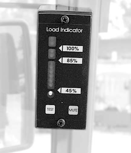
a 6greenLEDs–indicationofloadsbetween45%and85% of thesafeworkload
b 2yellowLEDs–indicationofloadsupto100%of thesafeworkload
c 2redLEDs–indicationofloadsupto110%of thesafeworkload
d GreenLEDstosignalreadiness
e Tipswitchforcheckingthesystem
f Tipswitchforadjustingthevolumeoftheaudiblesignal
AP0902 3–43 Operation
3.5.3Safeloadindicator
c b a d e f 14
Fig.75:Electronicloadindicator
Operation
Whattodoif...
• GreenLED d comeson?
➥ OK;loadindicatorisready
• GreenLEDs a (1-6)comeon?
➥ OK;theloadisbetween 45% and 90% of thesafeworkload
• YellowLEDs b (7-8)comeoninaddition?
➥ Workwithcaution;theloadisbetween 85% and 100% ofthe safeworkload
• Green a andyellowLEDs b areflashing,theacousticsignalisgiven?
➥ Workwithextremecaution!100% ofthe safeworkload isreachedcorrespondingtotheloaddiagram
• RedLEDs c comeon?
➥ OVERTURNINGHAZARD! Reducetheloadimmediatelybyretractingthe telescopicunit!Theloadisbetween 100% and 110% ofthe safeworkload!
• Thecompleteindicatorisflashing,theacousticsignalisgiven,althoughtheTESTtip switchhasnotbeenactivated?
➥ Theloadindicatorisdefective.Haveitimmediatelycheckedandrepairedbyan expert!
Functionalcheck
NOTE: Thecheckmaybeperformedatanytime,evenduringoperation.
☞ Proceedasfollows:
• PressTESTtipswitch e
AllLEDsareflashingandtheacousticsignalisgiven:
➥ Inworkingorder
Acousticsignalsoundsuninterruptedlyfor10seconds,then2redand1,2or3green LEDscomeoninaddition:
➥ Systemerror;havethesafeloadindicatorimmediatelybecheckedandrepairedby anexpert!
Adjustingsignalvolume
☞ Proceedasfollows:
• PressTESTtipswitch e
Whiletheacousticsignalisgiven:
• PresstheMUTEtipswitch f untilthedesiredvolumeisset
3–44 AP0902
3.5.4Controlvalveforthetelescopicunit:overview
WARNING!
Unintentionaloperationofthecontrollever76/21maycauseanaccidentwhen drivingonpublicroads
☞ Lockthecontrollever–seeBeforedrivingthemachineonpage3-20
•
Securingthecontrolleverfordrivingonpublicroads
Toengage:
☞ FollowtheinstructionsgiveninSection3.4.5„Beforedrivingthemachine”
☞ Pushcontrollever 21 downinneutralposition

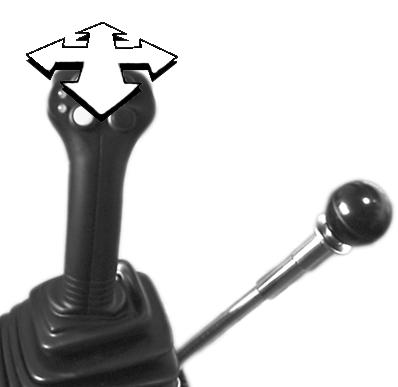
➥Thecontrolleverislockedinthisposition,itcannotbemoved
Disengagingthelock:
☞ Pulllever 21 up
AP0902 3–45 Operation
Controlleverforhydraulicsofliftand tiltcylinderoftelescopicunit
21
A B C D Position Symbol Lever21 Function • A ☞ Totheleft ➥ Rollbackattachment
B ☞ Totheright ➥ Tiltoutattachment
C ☞ Forward ➥ Lowerstheliftarm
Fig.76:Telescopicunit:controllever
•
•
D ☞ Backward ➥ Raisestheliftarm
21
Fig.77:Securingthecontrolleverfordrivingonpublic roads
Operation
Controlleverforattachmentsand3rd controlcircuit
22
Position Lever22 Function
A ☞ Forward ➥ Unlocksquickhitchfacility
Attachmentwithhydraulicfunction: ➥ E.g.opensthemultipurposebucket
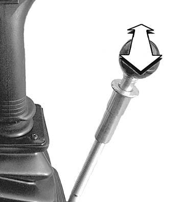
B ☞ Backward ➥ Locksquickhitchfacility
Attachmentwithhydraulicfunction: ➥ E.g.closesthemultipurposebucket
Lockfordrivingonpublicroads
Toengage:
☞ Turnlocksleeve 23 untilitispulleddown
➥ Lever 22 islocked
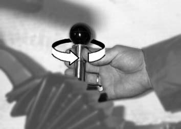
Toopenpermanently:
☞ Pulllocksleeve 23 uptothelimitandturnituntilitstaysinthetopposition
➥ Lever 22 canbemovedforwardandbackward
Toopenbriefly:
☞ Pulllocksleeve 23 uptothelimitandholditinthisposition
➥ Aslongaslocksleeve 23 isbeingpulledupward,lever 22 canbemoved.
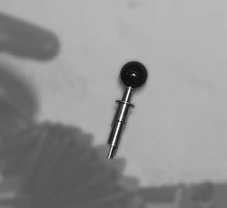
3–46 AP0902
Fig.78:Controlleverforattachments
23 B A
23 22
Fig.79:Securingthecontrolleverfordrivingonpublic roads
3.5.5Loweringthetelescopicuni twiththeengineswitchedoff
☞ Proceedasfollows:
• Makesurethatno-oneisdangerouslyclosetothetelescopicunit
• Pushcontrollever 21 forward(C),untilthetelescopicunitisfullylowered
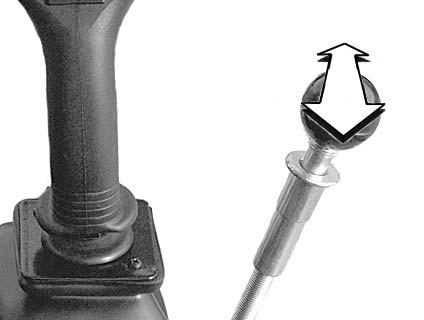
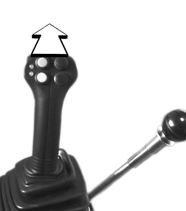
• Returncontrollever 21 toneutral
NOTE:
Thehydraulicsystemofthe3rdcontrolcircuit/attachmentisstillpressurizedeven whentheengineisnotrunning!Thehydraulicquickcouplerscanbereleased, howevertheycannotbere-attachedbecausethepressureinthehydrauliclinesis toohigh.Therefore:
☞ Depressurizesectionsofthesystemandhydrauliclineswhicharetobe openedbeforestartingsetuporrepairwork,e.g.fitting/removinganattachment!
☞ Depressurizeasfollows:
• Applyparkingbrake16/25 –see Parkingbrake[25] onpage3-10
• Switchofftheengine
• Movelever 22 forwardandbackwardseveraltimes
➥Hydraulicpressureisreleased
AP0902 3–47 Operation
3.5.6Relievingpressurethequickcouplersonthetelescopicunit
C 21
22
Fig.80:Loweringthetelescopicunitwiththeengine switchedoff
Fig.81:Depressurizinghydrauliclines
Operation
3.5.7Installinganattachment
Installinganattachmentonthetelescopicunitisdescribedbelowforthestandardbucket! Ifyouarefittingorremovingattachmentswithhydraulicfunctions–e.g.multipurposeor sidedumpbucket–youmustfollowthespecialinformationgivenintheoperator’smanual ofthecorrespondingattachment.
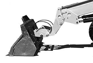
Fittingattachmentsontothequick hitchfacility
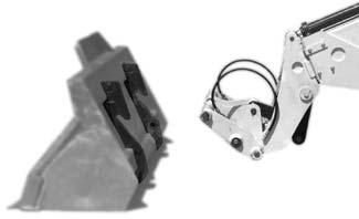
WARNING!
Theattachmentmustalwaysbesafelylockedontothequickhitchfacilityto avoidaccidents.
☞ Beforestartingwork,besurethattheattachmentissecurelylockedonto thequickhitchfacilitybymeansofthelockcylinder.Youmustbeableto seethelockpinsonbothsidesofthemountingholes.
☞ Proceedasfollows:
• Drivethemachineuptotheattachment
• Tiltthequickhitchfacilityallthewayforward.Todothis: Pushlever 21 totheright( B)
• AdjusttheheightofthepinshanksLofthequickhitchfacilitysothattheyareunder thecatchhooks K oftheattachment.Todothis:
• Driveforwarduntilthepinshanks L ofthequickhitchfacilityaredirectlybeneaththe catchhooksoftheattachment K
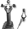
3–48 AP0902
Fig.82:Drivinguptotheattachment 21 K L Telescopicunit Lever21 • Lower ☞ Pushforward(C) or • Lift ☞ Pullbackward( D)
L K
Fig.83:Pickingupanattachment
• Raiseloaderlinkage().Todothis: Pulllever 21 backward( D)and
• Tiltinthequickhitchfacility().Todothis: Pushlever 21 totheleft(A )

• Securetheattachmentwiththelockpinofthequickhitchfacility.Todothis: Pulllever 22 backward( F)
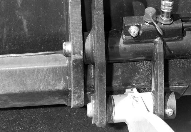
➥Lockpin G engagesinthemountingboresoftheattachment
• Makesurethatthetool/attachmentissecurelylockedontothequickhitchfacility!
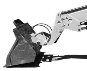
NOTE:
Youmustbeabletoseecatchbolt G on bothsides ofthemountingboresonthe attachment,asinfigure86/G
Attachmentswithhydraulicfunction:
• Switchofftheengine
• Attachthehydraulicand,ifused,electricalconnectionsfortheattachmentinaccordancewithitsoperator’smanual
Themachinecanbeequippedwitha4polefrontsocket(option).Withrockerswitch 48, thepowersupplyforelectricallyoperatedfrontattachments,e.g.aspraywaterpumpfora rotarybroom,canbepermanentlyswitchedONandOFF.
AP0902 3–49 Operation
Connectionofelectricallyoperated attachments(option)
21
Fig.84:Liftingtheattachment
22 G
Fig.85:Securingtheattachment
G
Fig.86:Checkingthelockpins
48 B A Powersupplyforfrontattachments(option) ON ☞ Pressrockerswitch 48 in position A
➥ Thepowersupplyatthefrontsocketis switchedon ➥ WarningLightinswitchcomeson OFF ☞ Pressrockerswitch 48 in position B (above) ➥ Powersupplyisinterrupted ➥ WarningLightgoesout
Fig.87:Switchforattachments(option)
(down)
Operation
Takinganattachmentoffthequick hitchfacility
WARNING!
Toavoidinjury,theattachmentmustbeplacedonthegroundsothatitwillnot falloverwhenremoved
☞ Positiontheattachmentsothatafterremovalitwillstandsafelyandwillnot tipover.
☞ Taketheattachmentoffthequickhitchfacilityasfollows:
• Drivethemachinewithemptyattachmentuptothestoragelocation.
• Rollbackthequickhitchfacility().Todothis: Pushlever 21 totheleft(A )
• Lowertheloader()untiltheattachmentisabout2–4in(5-10cm)abovethe ground.Todothis: Pushlever 21 forward( C)
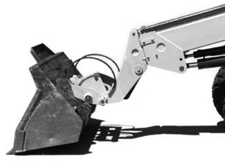
Attachmentswithhydraulicfunction:
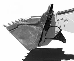
• Switchofftheengine
• Changeroundthehydraulicconnections(figure89)fromtheattachmenttothelock cylinder,inaccordancewiththeoperator’smanualoftheattachment
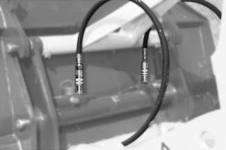
• Releasethelockonthequickhitchfacility.Todothis: Keeptipswitch 54 inposition A depressedandsimultaneously

• Retractthelockpinofthequickhitchfacility.Todothis: Pushleverforward88/22 forward(88/E)
• Tiltquickhitchfacilityslightlyforward().Todothis: Pushlever 21 totheright( B)
• Lowerthebucketfully().Todothis: Pushlever 21 forward( C)
3–50 AP0902
21
22
Fig.88:Loweringandtiltingintheattachment
Fig.89:Changingroundthehydraulicconnections
54 B A
Fig.90:Unlocksthequickhitchfacility
21 22
Fig.91:Takingofftheattachment
Assoonasthepinshanks L ofthequickhitchfacilityarebeneaththecatchhooks K ofthe attachment:
• Reverseawayfromtheattachment
3.5.8Connectingpress urizedquickcouplers
WARNING!
Toavoidinjury,useextracarewhenconnectingpressurizedquickcouplers.
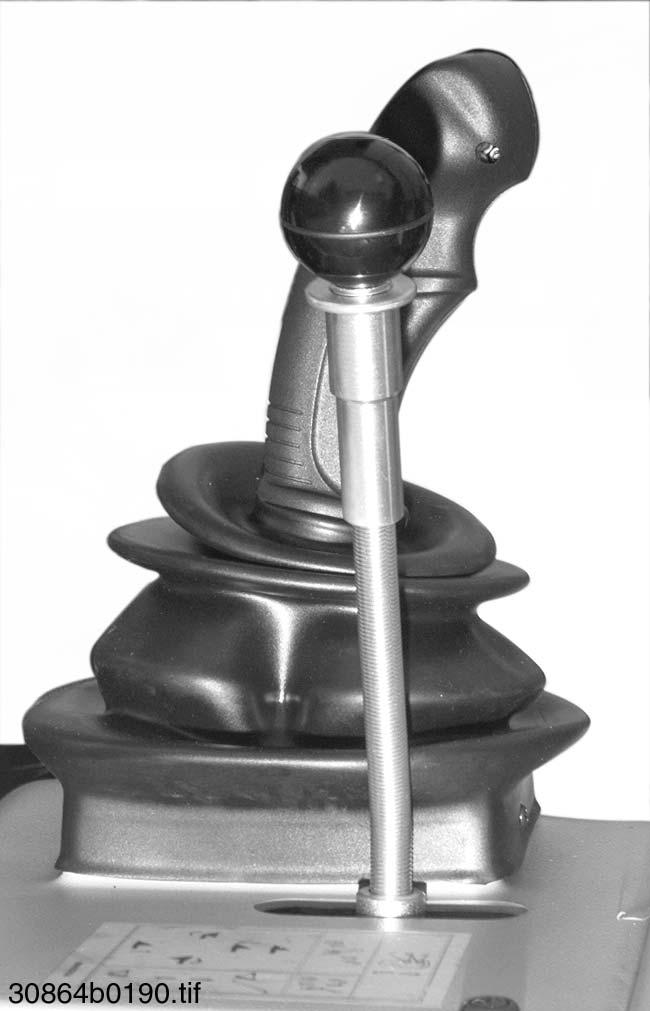
☞ Depressurizesectionsofthesystemandhydrauliclinesthataretobe openedbeforestartingsetuporrepairwork,e.g.fitting/removinganattachment!
seeRelievingpressurethequickcouplersonthetelescopicunitonpage 3-47.
☞ Neverconnectpressurizedquickcouplersbyforce
NOTE:
Oiltemperatureandpressureinthecylindercanriseifanattachment(e.g.side dumpbucketormultipurposebucket)orthequickhitchfacilityisexposedtothe sunforalongperiodoftime,withoutbeingconnectedtothemachine.Thispressurecannotbeloweredbymeansofdepressurization(asdescribedin section3 “Relievingpressurethequickcouplersonthetelescopicunit” onpage3-47 )
Thefollowingdescribeshowtoconnectapressurizedquickhitchfacility.Proceedaccordinglyforconnectionofpressurizedattachments.
Connectpressurizedquickcouplersasfollows:
☞ Fittheattachmentontothequickhitchfacility(pressurizedattachment),orremovethe hydrauliclinesfromtheattachment(pressurizedquickhitchfacility)
☞ Switchofftheengine
☞ Depressurizeasdescribedinsection3“Relievingpressurethequickcouplersonthe telescopicunit”onpage3-47
☞ Pulllever 22 backwardandlockit.Todothis:
• Turnlocksleeve 23 untilitispulleddown
AP0902 3–51 Operation
L K 22
Fig.92:Reversingfromtheattachment
23
Fig.93:Lockingthecontrollever
☞ Connecthydraulicline A (ontheright)onthemachine,toblueplug C ofthequickhitch facility(ontheleft,crosswise!)
☞ Removehydraulicline A again
☞ Connecthydraulicline A toblueplug D ofthequickhitchfacility(ontheright)
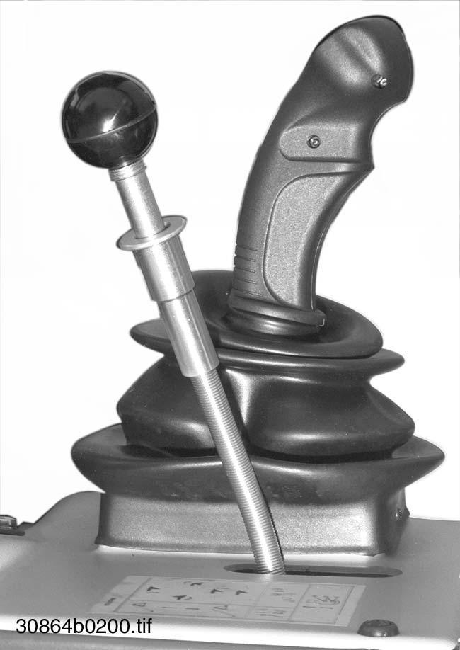
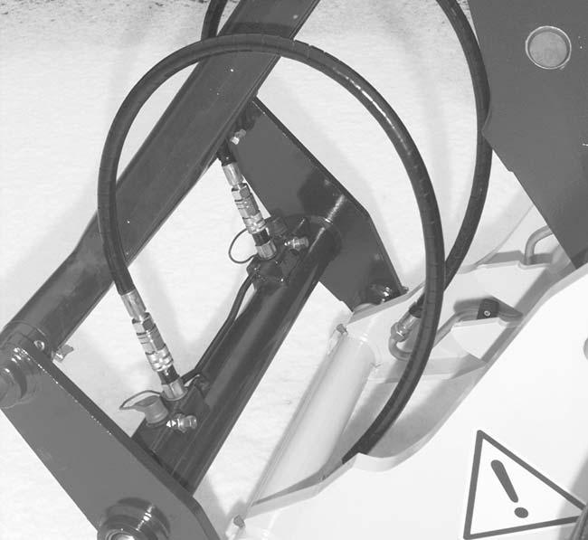
☞ Connecthydraulicline B toredplug C ofthequickhitchfacility(ontheleft)
☞ Releaselockoflever 22
☞ Returnlever 22 backtoneutral
☞ Locktheattachment–seesection3.5.7Installinganattachmentonpage3-48
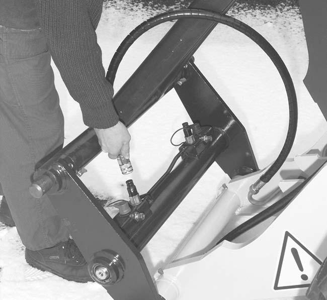
3–52 AP0902
Operation
A C
Fig.94:Depressurization
A B C D 22
Fig.95:Connectinghydrauliclines
23
Fig.96:Releasingthelock
3.5.9Operationofth etelescopicunit
WARNING!
Adefectivesafeloadindicatororworkingatmorethan100%ofthesafework loadmaycausethemachinetotiltandmayresultinanaccident.
☞ Checkthesafeloadindicatordaily!
☞ Aflashingindicatorandanaudiblesignalwarnofloadsexceeding100%. Theoperatormustreducetheloadbelowthe100%limitbyretractingthe telescopicunit!
Lift
☞ Proceedasfollows:
• Raisetheretractedtelescopicunittotherequiredheight.Todothis: Pulllever 21 backward( D)

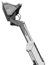
• Extendthetelescopicunit.Todothis: Pressthetipswitch 63 andholdinthispositionuntilthetelescopicunitisextendedto therequiredlength
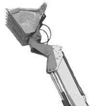
AP0902 3–53 Operation
1 21
Fig.97:Liftingthetelescopicunit
2 63
Fig.98:Retractthetelescopicunit
Lower
☞ Proceedasfollows:
• Retractthetelescopicunit.Todothis: Presstipswitch 64 untilthetelescopicunitiscompletelyretracted
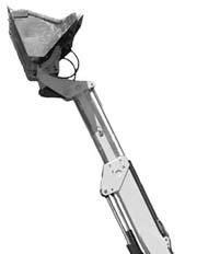
• Lowertheretractedtelescopicunit.Todothis: Pushlever 21 forward( C)
3–54 AP0902
Operation
1
64 21
Fig.99:Retractthetelescopicunit
2
Fig.100:Loweringthetelescopicunit
3.5.10Safetydevice“Hoseburstvalve“
NOTE:
Whenworkingwithliftinggearandcertainattachments,thehydrauliccylinderof thetelescopicunitmustbeequippedwith“hoseburstvalves”–see Applications withliftingaccessories onpage2-7. Theypreventthetelescopicunitfromsuddenlyloweringordumpingoutwhena hoseorpipebursts.
WARNING!
Damagetothehydraulicsystemleadstoactivationofthe“hoseburstvalve andmayresultinanaccident–
☞ Unlocktheemergencyloweringofthehoseburstvalveonlyinanemergency.
☞ Havedamagetothehydraulicsystemandtothehoseburstvalveimmediatelyrepairedandcheckedbytrainedpersonnel
Intheeventofdamagetothehydraulicsystem:
☞ Immediatelystopthemachine
☞ Applytheparkingbrake
☞ Firstretractthepush-outcylinderifpossible
☞ Switchofftheengine
☞ Removetheignitionkey
☞ Blockthemachine
Environment!
Collectthedrainedhydraulicoilinasuitablecontainer.Disposeofdrainedhydraulicoilin anecologicallysafemethod!
Alwayscontacttherelevantauthoritiesorcommercialestablishmentsinchargeofoildisposalbeforedisposingofbiodegradableoil.
☞ Collectthedrainedoilanddisposeofitinanecologicallysafemethod!
AP0902 3–55 Operation
Emergencyloweringontheliftcylinder
WARNING!
Emergencyloweringoftelescopicunitmayresultinanaccident.
☞ Firstretractthepush-outcylinderifpossible!
☞ Keepclearofthehazardzoneunderthetelescopicunit,alwaysapproach fromthesides!
☞ Donotactuatetheemergencyloweringoftheliftcylinderfromthefront,but throughthelateralboreintheframe!
☞ Alwaysactuateemergencyloweringwithextremecare
☞ Actuatetheemergencyloweringontheliftcylinderasfollows:
• Firstcarefullyretractthepush-outcylinder
• Removelocknut A
• Carefullyturnoutscrew B by1to2turnsuntilthetelescopicunitstartslowering
• Collectthedrainedoilanddisposeofitbyanecologicallysafemethod!
• Carefullylowerthetelescopicunittotransportposition
• Tightenscrew B again,counteringitwithlocknut A
• Drivethemachineoutofthehazardzonewiththebucketlowered
☞ Havethesettingofthehoseburstvalvecheckedbyaspecialist.Havethehoseburst valvereplacedifnecessary
Emergencyloweringonthepush-out cylinder
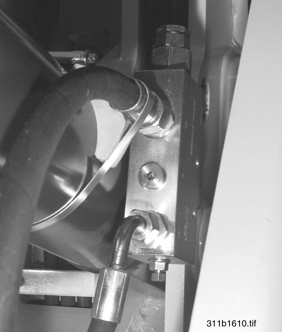
☞ Actuatetheemergencyloweringonthepush-outcylinderasfollows:
• Donotretracttheliftcylinder!
• Carefullyturnoutscrew A byabout1/2turnuntilthetelescopicunitstartsretracting
• Carefullyretractthetelescopicunitagainstthelimitstop
• Firmlyretightenscrew A
• Carefullylowerthetelescopicunitwiththeliftcylinderintotransportposition
• Drivethemachineoutofthehazardzonewiththebucketlowered
☞ Havethesettingofthehoseburstvalvecheckedbyaspecialist.Havethehoseburst valvereplacedifnecessary
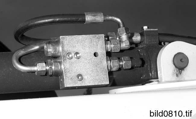
3–56 AP0902
Operation
A B
Fig.101:Hoseburstvalveforliftcylinder(option)
A
Fig.102:Hoseburstvalveonpush-outcylinder(option)
☞ Actuatetheemergencyloweringonthetiltcylinderasfollows:
• Firstcarefullyretractthepush-outcylinder
• Carefullylowerthetelescopicunittotransportposition
• Carefullyextendthepush-outcylinderuntiltheboreontheleftsideofthetelescopic unitcanbeaccessed
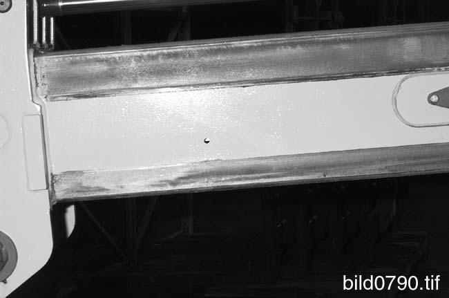
• Carefullyturnoutscrew A byabout1/2turnuntiltheattachmentstartsdumping
• Retightenscrew A
• Drivethemachineoutofthehazardzonewiththebucketlowered
☞ Havethesettingofthehoseburstvalvecheckedbyaspecialist.Havethehoseburst valvereplacedifnecessary
AP0902 3–57 Operation
Emergencyloweringonthetiltcylinder
A
Fig.103:Hoseburstvalveontiltcylinder(option)
Operation
3.5.11Workingwithstandardbucketandpalletforks
Standardbucket
Thefollowingsectiondescribesworkoperationswiththemachineequippedwiththestandardbucket.
Thestandardbucketismainlyusedfordiggingearth,andforloosening,lifting,transportingandloadinglooseorsolidmaterials.
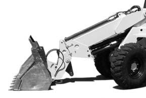
Checkingthetiltpositionofthebucket
NOTE:
Angleofredmarking A ontopofthebucketisthesameastheangleofthecutting blade B
Checkingthetransportpositionofthebucket
NOTE:
Thebucketisintransportpositionwhenthe
•Telescopicunitisfullyretractedand
•Bucketisrolledbackincompletely(A )and
•Marks C ontheliftframeandthemachineframearelinedup(figure106)
Withbothmarks C aligned,transportgroundclearancewillbeatleast10in (230mm).(105/B ),withstandardbucket(810136)andstandardtires(12.5-20).
3–58 AP0902
A B B A
Fig.104:Tiltpositionofthebucket
Fig.105:Transportpositionofthebucket
C
Fig.106:Marksfortransportposition
Transportingwithafullbucket
WARNING!
Itishazardoustotransportfullbucketsintheraisedposition.Beespecially carefulwhenturningordrivingonslopes.Thelowerthebucketandthecenter ofgravity,thelesschancethereisoftippingover.
☞ Toavoidaccidents:
•Completelyretractthetelescopicunit
•Rollbackthebucketalltheway
•Raisethebuckettothetransportposition
☞ Proceedasfollows:
• Completelyretractthetelescopicunit
• Rollbackthebucketalltheway(105/A )
• Lowerorraisethetelescopicunittotransportposition(105/B)
AP0902 3–59
Operation
Operation
Loadingloosematerial
WARNING!
Donotloadorpushmaterialwiththetelescopicunitextendedasthismay resultinanaccident.
☞ Completelyretractthetelescopicunitforloadingorpushingmaterial!
☞ Proceedasfollows:
• Completelyretractthetelescopicunit
• Selectlowdriverange
• Alignthebladeparallelwiththeground(A )–seealso“Checkingthetiltpositionofthe bucket”
• Lowerthebuckettotheground( B ).Todothis: Pushlever 21 forward( C)
• Driveforwardintothematerial(108/A)
Whentheenginespeeddecreases:
• Raisethebucketslightly B ).Todothis: Pulllever 21 backward(D)
3–60 AP0902
A
B 21
Fig.107:Horizontalloweringofthetelescopicunit
B A 21
Fig.108:Drivingintothematerial
Ifthematerialishardtopenetrate:
☞ Proceedthesameasforloadingloosematerial,butinaddition:
• Tiltthebucketgentlyinandout.Todothis: Movelever 21 totheleftandright(A and B)
Endingloading:
☞ Proceedasfollows:
• Rollbackinbucket( C).Todothis: Pushlever 21 totheleft(A )
• Reduceenginespeed
• Reverseoutofthematerial(A)
• Raisethebuckettotransportposition(B )
AP0902 3–61
Operation
21
Fig.109:Loading,ifthematerialishardtopenetrate
C 21
Fig.110:Rollbackinthebucket
B A
Fig.111:Reversingoutofthematerial
Operation
Removingmaterial/digginginsoftsoil
WARNING!
Donotunderminefoundationsorwallsbecauseofthechanceofcollapse!
☞ Neverunderminefoundationsorwalls!
☞ Proceedasfollows:
• Completelyretractthetelescopicunit
• Selectlowdriverange
• Placebuckettotheground( B ).Todothis: Pushlever 21 forward( C)
• Setdiggingangle α (113/1).Todothis: Pushlever 21 totheright( B)
• Drivethemachineforward(114/1) Oncethebuckethaspenetratedthesoil:
• Setdiggingangle α slightlyflatter(114/2).Todothis: Pushlever 21 totheleft(A ),sothat: •Layerbeingremovedisasevenaspossibleand •Toreducewheelspin
• Proceedthesameasforloadingloosematerial
3–62 AP0902
B 21
Fig.112:Loweringthetelescopicunit
α
1 1 21
Fig.113:Settingthediggingangle
2 1 21
Fig.114:Removinganevenlayer
Removingmaterial/digginginhardsoil
Proceedasfollows:
• Completelyretractthetelescopicunit
• Selectlowdriverange
• Lowerbuckettotheground(115/1).Todothis: Pushlever 21 forward(C)
• Setdiggingangle α slightlyflatter(115/ 2)thanfordigginginsoftsoil.Todothis: Pushlever 21 totheleft(A )
• Drivethemachineforward(115/3)and
• Pressthebucketdownwardslightly.Todothis: Pushlever 21 slightlyforward( C)
Oncethebuckethaspenetratedthesoil:
• Setdiggingangle α slightlyflatter(116/ 1).Todothis:
Pushlever 21 totheleft(A ),sothat:
•Layerbeingremovedisasevenaspossibleand
•Toreducewheelspin
• Pushlever 21 totheleft(A ),ormoveitalternatelytotheleftandright( A and B),to loosenthematerial
• Proceedthesameasforloadingmaterialthatishardtopenetrate
AP0902 3–63
Operation
2 1 3 21
Fig.115:Removinghardsoil
1 21
Fig.116:Settingthediggingangleflatter
Loadingheapedmaterial(non-compactedmaterial)
WARNING!
Diggingunderheapedmaterialcancauseittocollapse.
☞ Neverundermineheapedmaterial!
☞ Proceedasfollows:
• Completelyretractthetelescopicunit
• Selectlowdriverange
• Setthecuttingbladeofthebucketparalleltotheground.Todothis: Pushlever 21 totheleftorright( A and B)
• Lowerthetelescopicunithorizontaltotheground.Todothis: Pushlever 21 forward( C)
• Driveforward
Afterpenetratingtheheapedmaterial:
• Smoothlyliftthetelescopicunit
• Keepthebucketlevel
Whenthetelescopicunitstopsraising:
• Rollbackthebucket(118/1)
• Raisethetelescopicunit(118/2)
• Reverseawayfromtheheapedmaterial(118/3)
• Lowerthetelescopicunittotransportposition
Loadingheapedmaterial(compactedmaterial)
Proceedasfollows:
• Completelyretractthetelescopicunit
• Selectlowdriverange
• Proceedasfornon-compactedmaterial,howeverwhenraisingthetelescopicunit throughtheheapedmaterial:
• Rollbackthebucketinandoutslightly(119/1).Todothis: Movelever 21 alternatelytotheleftandright(A and B)
➥Materialisloosened
3–64 AP0902
Operation
21
Fig.117:Penetratingtheheapedmaterial
1 3 2 21
Fig.118:Reversingawayfromheapedmaterial
1 21
Fig.119:Heapedcompactedmaterial
Grading
Afterhavingfinishedremoving/loadingthematerial:
• Selectlowdriverange
• Lowerthetelescopicunittotheground(120/1)
• Reverseacrossthesurfacetobegraded(120/2)
Furtherpracticalhintsfordigging
Whenplanningandcarryingoutdiggingwork,werecommendthatyouobservethefollowingpoints:
• Exitsfrompitsshouldbeoutsidethedigginglineandshouldbeaslevelaspossible
• Digbyremovingadjacentstripsifpossible
• Makesureyoucandriveforwardwhendrivingoutofthediggingareawithafully loadedbucket
• Wheneverpossible,driveinreversewhentransportingafullbucketdownasteepslope
Loadingmachines
Whenloadingmachines,werecommendtotakeintoaccountthefollowing:
• Selectlowdriverange
• Ifpossible,thelorryandtheworkingdirectionofthemachineshouldformanangleof 45°(figure121)
• Onlyraisethefullbuckettothedumpingheightwhenyouaredrivinginastraightline towardthelorry
• Withdustymaterials: Ifpossibledumpwiththewindbehindyoutokeepthedustawayfromyoureyes,air filtersandfans
Freeingthemachine
☞ Ifyourmachinegetsstuckintheground:
• Selectlowdriverange
• Dumpoutthebucketuntilthecuttingedgeisverticalabovetheground
• Lowerthebucketalltheway
• Graduallyrollbackthebucket
➥Themachinewillbepushedbackward
• Reverseslowly
• Repeatthisprocedureuntilthewheelsreachfirmground
• Reversethemachineaway
AP0902 3–65
Operation
1 2
Fig.120:Grading
Fig.121:Loadingmachines
Operation
3.5.12Workingwithpalletforks
Safetyinstructions
• ObservetheinstructionsinSection 3.5.3„Safeloadindicator” onpage3-43.Thedriver mustbeawareofthesignalsgivenbythesafeloadindicator
• Followthespecialinstructionsintheattachment'soperator’smanual!
• Donotlowertheextendedtelescopicunitfromahighforkarmposition–alwaysretract thetelescopicunitfirst
• Moveascloseaspossibletothematerialtobeloaded
• Movetothematerialtobeloadedwiththewheelsalignedstraightahead!
• Ifpossible,loadthematerialwiththetelescopicunitretracted,asloadingwiththe extendedunitmayaffectthestabilityofthemachine!
• Alwaysworkonfirmandlevelgroundwithsufficientbearingcapacity(forafullyloaded machine)!
• Neverlifttheloadwithonlyoneforkarm!
• Keepaminimumdistanceof6mbetweentelescopicunit/loadandtowerlines!
• Beforecommencingwork,makesurethattheforkarmsontheforkframearesafely locked!
• Donotoperatetelescopicunitorattachmentswhendrivingathighspeed!
• Donotleavethemachinewiththeloadliftedandthetelescopicunitextended!
Approachingthematerial
☞ Proceedasfollows:
• Stopthemachineimmediatelyinfrontofthematerial
• Applyparkingbrake16/25
• Setdriveswitchtoneutral–see Drivingdirectionselectorswitch onpage3-8
• Aligntheforkarmsparallelwiththeground
• Checkthedistanceoftheforkarmstothecenterline(dashedlineinfigure123) Theforkarmsmustbe:
•Atthesamedistancetothecenterline
312b0850.eps
•Asfarapartaspossible
3–66 AP0902
Fig.122:Positionofmachineandtinestowardsthematerial
Fig.123:Checkforkspacing
Loadingthematerial
☞ Proceedasfollows:
• Adjusttheheightoftheforkarmssothatthepalletcanbecorrectlyloaded
• Movecarefullyforwarduntiltheforkframeisincontactwiththematerial
• Makesurethatthepalletissafelyloadedontheforkarms
• Applyparkingbrake25
• Movedrivelevertoneutral–see Drivingdirectionselectorswitch onpage3-8
• Liftthetelescopicunit slowly andmakesurethatthelimitsofloaddiagramandsafe loadindicatorarenotexceeded!
• Incaseofdoubtordanger,lowertheloadimmediately!
• Tilttheforkframebackwards( 1)
• Completelyretractthetelescopicunit( 2)
• Intransportposition,lowerthetelescopicunitasfaraspossible(3)
• Makesurethatnothing/nobodyisinthewaywhenreversing
• Engagereversegear
• Releaseparkingbrake16/25
• Reverseslowlyfromthestack(4)
AP0902 3–67
Operation
Fig.124:Loadthematerial
Fig.125:Liftthetelescopicunit(
1 2 3 4
Fig.126:Movethematerialtotransportposition
4
Fig.127:Reversefromthestack
Operation
Settingdownthematerial
☞ Proceedasfollows:
• Movestraightaheadtothestackwiththetelescopicunitretractedandloweredto transportposition,andtheforkframeslightlytiltedback
• Applyparkingbrake16/25
• Setdriveswitchtoneutral–see Drivingdirectionselectorswitch onpage3-8
• Raisethetelescopicunit(1)
• Carefullyextendthetelescopicunit(2)untiltheloadispositionedpreciselyabovethe stack
• Puttheforkarmslevelagain(3)
• Lowerthetelescopicunit slowly (4),makingsurethatthepresetlimitsofload diagramandsafeloadindicatorarenotexceeded!Incaseofdoubtordanger,stop stackingimmediately!Todothis:
•Firstretractthetelescopicunitandthen
•Lowerthetelescopicunit
• Toaligntheloadwiththestack,carefullyretract/extendthetelescopicunit
• Lowertheload
• Makesurethattheforkarmsarefreefromloadandthatnothing/nobodyisinyour way,beforereversingfromthestack
• Retractthetelescopicunit
• Lowerthetelescopicunittotransportposition
• Tilttheforkframetotheback
3–68 AP0902
4 3 2 1
Fig.128:Liftthetelescopicunit
Section4
Troubleshooting
Theinformationgiveninthissectionisintendedformaintenancepersonnelwhencarrying outrepairwork.Itallowsforfastandreliabledetectionoferrorsandmalfunctionssothat appropriatemeasurescanbetakenfortroubleshooting. Thedetaileddescriptionofrepairworkislimitedtotheworkthatcanbecarriedoutbypersonswithoutspecialtraining.
AP0902 4–1 Troubleshooting 4 4Troubleshooting
Troubleshooting
Troubleshooting
4.1Enginetrouble
4–2 AP0902
Problem Possiblecauses Checkedbyoperator Checkedbyworkshop Starterturnstooslowly1,2,3,4 Enginedoesnotstart5,6,7.8,9,10,12,13,14,15,1734,35,36,37.38,42,43,44 Enginenoteasytostart 5,7.8,9,10,11,12,13,14,15,16, 17.19 34,36,37.38,40,42,43,44 Insufficientoutput 8,9,10,11,12,13,16,17.18,19,20, 21 34,36,37.38,39,42,43,44,63 Interruptedengineoperation8,9,10,12,13,15,20,2234,36,37.38,39,40,41,43 Highfuelconsumption11,13,15,17.18,19,21,2234,36,37.38,39,40,42,43,44,63 Blacksmoke11,13,15,17.19,21,2234,36,37.38,39,40,42,43,44,63 Blueorwhitesmoke4,15,21,2336,37.38,39,42,44,45,52,58,62 Oilpressuretoolow4,24,25,2646,47.48,50,51,59 Engineknocks9,13,15,17.20,22,2336,37.40,42,44,46,52,53,60 Irregularenginespeeds 7.8,9,10,11,12,13,15,16,18,20, 22,23 34,38,40,41,44,52,60 Vibrations13,18,20,27.2834,38,39,40,41,44,52,54 Oilpressuretoohigh4.2549 Enginetemperaturetoohigh11,13,15,19,27.29,30,32,6534,36,37.39,52,55,56,57 Pressureincrankcasetoohigh31,3339,42,44,45,52 Compressiontoolow11,2237.39,40,42,43,44,45,53,60 Enginestartsandstopsrightafter10,11,12
4.1.1Possiblecause sformalfunctions
tionpump
37Incorrectvalvetiming
38Compressiontoolow
39Cylinder-headgasketleaks
40Blockedvalves
41Wronginjectionlines
42Cylinderboresworn
43Valveseatsleak
44Pistonringblocked,wornorbroken
45Valvestemsand/orguidesworn
46Crankshaftbearingwornordamaged
47Oilpumpworn
48Pressurereliefvalvedoesnotclose
49Pressurereliefvalvedoesnotopen
50Springinpressurereliefvalvebroken
51Defectiveoilsuctionpipeofoilpump
52Damagedpiston(s)
53Incorrectprojectionofpiston(s)
54Flywheelhousingorflywheelnotcorrectlyaligned
55Defectivethermostatorwrongthermostat
56Coolantchannelsconstricted
57Defectivecoolantpump
58Damagedvalvestemsealing
59Oilscreenfouled
60Valvespringbroken
61Notassigned
62Notassigned
63Intakesystemleaks
64Notassigned
65Drivebeltforcoolantpumpisloose
AP0902 4-3 Troubleshooting
3Defectivestarter 4Wrongoilgrade 5Starterturnstooslowly 6Fueltankempty 7Defectiveshutoffunit 8Fuellinesclogged 9Defectivefuelpump 10Fuelfilterfouled 11Intakesystemconstricted/airfilter fouled 12Airinfuelsystem 13Injectionnozzlesdamagedorwrong injectionnozzles
tem 15Defectivecoldstartingsystem 16Badfueltankventilation 17Wrongfuelgrade 18Limitedactionofcontrolsforspeed regulation 19Defective/cloggedexhaustsystem 20Enginetemperaturetoohigh 21Enginetemperaturetoolow 22Wrongsettingofvalveclearance
withtoomuchoiloroilwithwrong grade 24Engineoilleveltoolow 25Defectiveoilpressuresensor 26Oilfilterfouled 27Defectivebreather 28Defectiveenginesuspensionorflywheelhousing 29Engineoilleveltoohigh 30Limitedcirculationofairorcoolant throughradiator 31Breatherlineconstricted 32Coolantleveltoolow 33Vacuumlineleaksordefectivevacuum pump 34Defectivefuelinjectionpump 35Defectivedriveoffuelinjectionpump 36Incorrectstartofdeliveryoffuelinjec-
1Deadbattery 2Electricalconnectionsarenotinorder
14Incorrectoperationofcoldstartingsys-
23Oilbathaircleaner(ifinstalled)filled
Troubleshooting
Notes
4–4 AP0902
Maintenance 5
Section5
5.1Introduction
Beforecarryingoutserviceandmaintenancework,alwaysread,understandandfollow theinstructionsgivenin
• Part2“SAFETYINSTRUCTIONS”ofthisoperator’smanual
• Theoperator’smanualfortheengine
Dailyserviceandmaintenancework,andmaintenanceworkaccordingtomaintenance planA,canbecarriedoutbyspeciallytrainedoperators.Allothermaintenanceworkmust becarriedoutbyqualifiedmechanicsonly.
Theintervalsforthemaintenanceworkdescribedbelowarelistedinthemaintenance plansintheannex.
5.2Fuelsystem
5.2.1Specificsafetyinstructions
• Extremecautionisessentialwhenhandlingfuelbecauseoftheriskoffire!
• Neverworkonthefuelsystemiftheengineishot–e.g.forbleeding,changingfiltersor cleaningthewaterseparator!
• Neverperformworkonthefuelsystemnearopenflamesorignitablesparks!
• Donotsmokewhenworkingonthefuelsystemorwhenrefuelling!
• Beforerefuellingswitchofftheengineandremovetheignitionkey!
• Donotrefuelinenclosedareas!
• Wipeawayfuelspillsimmediately!
• Keepthemachinecleantoreducetheriskoffire!
AP0902 5–1 Maintenance 5
5Maintenance
Maintenance
5.2.2Refuelling
WARNING!
Allworkinvolvingfuelcarriesanincreasedriskoffireandpoisoning!
☞ Donotrefuelinenclosedareas
☞ Neverperformworkonthefuelsysteminthevicinityofnakedflamesor sparks
Environment!
Useasuitablecontainertocollectthefuelasitdrainsanddisposeofitinanenvironmentallyfriendlymanner!
NOTE:
Donotrunthefueltankcompletelydry.Otherwise,airisdrawnintothefuelsystem.Thisrequiresbleedingthefuelsystem–seesection5.2.6 Bleedingthefuel system onpage5-6.
StationaryfueltanksGeneral
Ifpossible,onlyrefuelfromstationaryfueltanks.Fuelfrombarrelsorcansisusuallycontaminated.
Eventhesmallestparticlesofdirtcancause
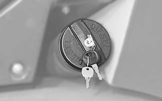
• Increasedenginewear
• Malfunctionsinthefuelsystemand
• Reducedeffectivenessofthefuelfilters
Refuellingfrombarrels
Ifrefuellingfrombarrelscannotbeavoided,notethefollowingpoints(seefigure130):
• Barrelsshouldneitherberollednortiltedbeforerefuelling
• Protectthesuctionpipeopeningofthebarrelpumpwithafine-meshstrainer
• Immerseitdowntomax.6in(15cm)abovethebottomofthebarrel
• Onlyfillthetankusingrefuellingaids(funnelsorfillerpipes)withanintegralmicrofilter
• Keepallrefuellingcontainerscleanatalltimes
5–2 AP0902
Maintenance
wrong right ✓ ✗
Fig.129:Fuelfillerinlet
Fig.130:Refuellingfromabarrel
Specificationfordieselfuel
Onlyusehigh-gradefuels:
Fortemperaturesbelow20°F(6°C)orfor operationabove1640yd(1500m)altitude
5.2.3Cleaningthefueltank
Environment!
Useasuitablecontainertocollectthefuelasitdrainsanddisposeofitinanenvironmentallyfriendlymanner!
Depositsofdirtparticlesandwaterinthetankcannotbeentirelyavoided.Thefueltank shouldthereforebecleanedoccasionally, particularlybeforewinteroperation. Cleanthefueltankwhenthefuellevelinthetankisaslowaspossible!
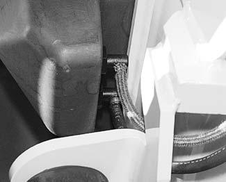
☞ Cleanthefueltankasfollows:
• Placeadriptrayunderfueltank A
• Unscrewreturnconnectionpiece B
• Flushoutthefueltankwithfuel,severaltimesifnecessary
• Screwreflexconnectionpiece B backin,tothelimit
• Unscrewreflexconnectionpiece B again,untilthecorrectpositionis reached–max.1turn!
• Fillthetank
• Checkreflexconnectionpiece B forleakage
AP0902 5–3 Maintenance
Grade Cetane number Application • No.2-D Min.45 Fornormaltemperatures
No.1-D
•
A B
Fig.131:Drainplugonfueltank
Maintenance
5.2.4Changingthefuelfilter
WARNING!
Ifthefuel,asitdrains,comesintocontactwithhotenginepartsortheexhaust system,thereisanincreasedriskoffire.
☞ Neverchangethefuelfilteriftheengineishot!
Environment!
Useasuitablecontainertocollectthefuelasitdrainsanddisposeofitinanenvironmentallyfriendlymanner!
☞ Changefuelfilter132/C asfollows:
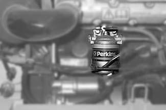
• Thoroughlycleantheoutsidesurfacesofthefuelfilter
• Firmlyholdlowercover133/6 ofthefilterandunscrewscrew133/1 onthefilterhead
• Pulllowercover133/6 ofthefilterdownward
• Removeanddisposeoffilter133/4
• Cleantheinsideofthefilterheadandthelowercover
• Replaceseals133/2 and133/5 andO-ring133/3 andapplyathincoatofcleanfuel
• Holdthelowercoverunderthenewfilterandplacethefilteronthefilterhead.Ensure correctpositionofthefilterontheO-ringinthefilterhead
• Placeandtightenscrew133/1
• Bleedthefuelsystem–seesection5.2.6 Bleedingthefuelsystem onpage5-6
• Makeatestrun–andcheckfortightness!
5–4 AP0902
A
Fig.132:Fuelfilterposition
Fig.133:Removingthefuelfilter
5.2.5Cleaningthefuel/waterseparator
WARNING!
Ifthefuel,asitdrains,comesintocontactwithhotenginepartsortheexhaust system,thereisanincreasedriskoffire
☞ Nevercleanthefuel/waterseparatoriftheengineishot!
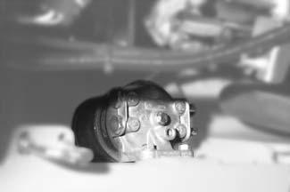
☞ Proceedasfollows:
• Placeadriptrayunderthefuel/waterseparator
• Unscrewthedrainplugonthelowerside
• Drainthewateruntilcleanfuelrunsout
• Screwinthedrainplugonthelowerside
• Testruntheengine
AP0902 5–5 Maintenance
B
Fig.134:Positionoffuel/waterseparator
5.2.6Bleedingthefuelsystem
WARNING!
Ifthefuel,asitdrains,comesintocontactwithhotenginepartsortheexhaust system,thereisanincreasedriskoffire
☞ Neverbleedthefuelsystemiftheengineishot!
Bleedthefuelsysteminthefollowingcases:
• Afterremovingandfittingthefuelfilterandthefuellinesbackonagain,or
• Afterrunningthefueltankempty,or
• Ifthefuelsystemleakswiththeenginerunning,or
• Afterrunningtheengineagain,afterithasbeenoutofserviceforalongperiodoftime
☞ Bleedthefuelsystemasfollows:
• Fillthefueltank
• Unscrewtheventscrew135/1 onthesideofthefuelinjectionpump
• Actuatethehandpumpleveronthefuelsupplypump135/2untilthefuelrunsoutfree ofairfromthebleedopening
• Tightenbleedscrew135/1
• Turntheignitionkeytothe“ON”position(1)
• Turnthestarteruntiltheenginestarts(15secondsmaximum) Iftheenginerunssmoothlyforawhile,andthenstops;orifitdoesnotrunsmoothly:
• Checkonceagainifthereisanyairinthefuelsystem Thepresenceofairinthefuelsystemisasignofleakageonthelow-pressuresideofthe fuelsystem!
• Switchofftheengine
• Turntheignitionkeytothe“OFF”position(0)
5–6 AP0902
Maintenance
Fig.135:Bleedingthefuelsystem
5.3Enginelubricationsystem
5.3.1Checkingtheengineoillevel
NOTE:
Checktheoillevelevery10servicehoursoreveryday.Werecommendchecking theoillevelbeforestartingtheengine;afterswitchingoffawarmengine,waitat least5minutesbeforechecking.
☞ Checktheoillevelasfollows:
• Parkthemachineonlevelground
• Switchofftheengine!
• Oildipstick136/1
•Pullitoutandwipeitwithalint-freecloth
•Pushitbackinasfaraspossible
•Withdrawand
•Readtheoillevel
• Topuptheoillevelifnecessary (atlatestwhentheoilreachestheMINmarkonthedipstick)
Important!
Excessiveorincorrectengineoilmayresultinenginedamage!Forthis reason:
☞ DonotaddengineoilabovetheMAXmark136/2 oftheoildipstick
☞ Useonlythespecifiedengineoil–seesection5.15Enginefluidsandlubricantsonpage5-39
Environment!
Collectthedrainedengineoilinasuitablecontaineranddisposeofitbyanecologically safemethod!
☞ Topuptheoillevelasfollows:
• Cleantheareaaroundoilfillercap A withalint-freecloth
• Opencap A
• Raiseoildipstick B slightlytoallowanytrappedairtoescape
• Addengineoil
• Waitamomentuntilalltheoilhasrunintotheoilsump
• Checktheoillevel–seesection5.3.1 Checkingtheengineoillevel onpage5-7
• Topupifnecessaryandchecktheoillevelagain
• Closeoilfillercap A
• Pushinoildipstick B intothefillerinletasfarasitwillgo
• Completelyremovealloilspillsfromtheengine
AP0902 5–7 Maintenance
5.3.2Toppinguptheengineoil
Fig.136:Checkingtheoillevel
Fig.137:Toppingupengineoil
A B
5.3.3Changingtheengineoil
WARNING!
Useextracautionwhendraininghotengineoil,becauseoftheriskofburns.
☞ Wearprotectivegloves
☞ Usesuitabletools
Environment!
Collectthedrainedengineoilinasuitablecontaineranddisposeofitbyanecologically safemethod!
☞ Changetheengineoilasfollows:
• Parkthemachineonlevelground
• Lettheenginerununtilreachingoperatingtemperature[oiltemperatureabout180°F (80°C)]
• Switchofftheengine
• Removemaintenancepanel A underthemachinerearend.Todothis: Releasescrews B
• Placeanoildriptray[withacapacityofabout8quarts(8liters)]undertheopening
• Unscrewfillercap C ofoildrainvalve E
• Unscrewoildraincoupling D withasufficientlylonghose,makingsuretheendofthe hoseisintheoildriptray
➥Oildrainvalve E opensandtheengineoildrains
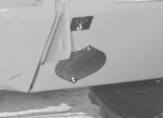
• Completelydraintheoil
• Unscrewoildraincoupling D
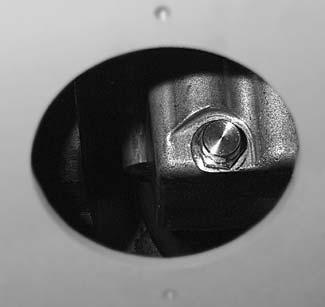
• Screwonfillercap C oftheoildrainvalve
• Fitmaintenancepanel A
• Fillwithengineoil–seesection5.3.2 Toppinguptheengineoil onpage5-7
• Starttheengineandrunitatlowspeedforashorttime
• Switchofftheengine
• Waitamomentuntilalltheoilhasrunintotheoilsump
• Checktheoillevelagain
• Topupifnecessaryandcheckagain
• Completelyremovealloilspillsfromtheengine
5–8 AP0902
Maintenance
A B
Fig.138:Maintenancepanel
C C D E
Fig.139:Engineoildrainplug
5.3.4Changingtheengineoilfiltercartridge
WARNING!
Useextracautionwhendraininghotengineoil,becauseoftheriskofburns.
☞ Wearprotectivegloves
Environment!
Useasuitablecontainertocollecttheengineoilasitdrains. Disposeofusedoilandfiltersinanenvironmentallyfriendlymanner!
☞ Changethefilterasfollows:
• Stoptheengine
• Placeasuitablecontainerundertheoilfiltertocollecttheoil
• Releaseandunscrewtheoilfiltercartridgeusingacommerciallyavailabletool
• Besurethethreadadapter140/1 iscorrectlyplacedinthefilterhead
• Cleantheinsideofthefilterhead
• Applyathincoatoffreshengineoiltotherubberseal140/2 ofthenewoilfilter cartridge
• Tightenthenewfiltercartridgebyhanduntilthegasketmakescontact
• Tightentheoilfiltercartridgebyhandwithafurtherhalforthree-fourthsofa revolution
• Makesuretheoilleveliscorrect!
• Runtheengineforashorttime
• Switchofftheengine
• Checkthesealoftheoilfiltercartridgeandretightenbyhand
• Checktheoillevelandaddengineoilifnecessary
• Completelyremovealloilspillsfromtheengine
• Disposeoftheusedoilfilterinanenvironmentallyfriendlymanner
AP0902 5–9 Maintenance
Fig.140:Engineoilfiltercartridge
5.4Engineandhydraulicscoolingsystem
Thecombinedoil/watercoolerislocatedintheenginecompartment,ontherightsideof theengine.Itcoolsthedieselengine,andthehydraulicoilofthedriveandwork hydraulics.
Theexpansiontankforthecoolantisalsolocatedintheenginecompartment,abovethe cooler.
5.4.1Specificsafetyinstructions
• Dirtonthecoolingfinsreducesthecooler’sheatrejectioncapacity!
Toavoidthis:
• Cleantheoutsideofthecooleratregularintervals.Refertothemaintenanceplansin theAnnexforthecleaningintervals
• Industyordirtyworkconditions,cleanmorefrequentlythanindicatedinthemaintenanceplans
• Aninsufficientcoolantlevelreducestheheatrejectioncapacityaswell,andcanleadto enginedamage!Therefore:
• Checkthecoolantlevelatregularintervals.Refertothemaintenanceplaninthe Annexfortheintervals
• Ifcoolantmustbeaddedfrequently,checkthecoolingsystemforleakagesand/or contactyourdealer!
• Neverfillincoldwater/coolantiftheengineiswarm!
• Afterfillingtheexpansiontank,conductatestrunwiththeengineandcheckthe coolantlevelagainafterswitchingofftheengine
• Theuseofthewrongcoolantcandestroytheengineandthecooler.Therefore:
• Addsufficientantifreezetothecoolant–butnevermorethan50%.Ifpossibleuse brand-nameantifreezethathaveanticorrosionadditives
• Observethecoolanttableinsection“Specifications”
• Donotusecoolercleaningcompoundsifantifreezehasbeenaddedtothecoolant–otherwisethiscausessludgetoform,whichcandamagetheengine
Environment!
Useasuitablecontainertocollectthecoolant asitdrainsanddisposeofitinanenvironmentallyfriendlymanner!
5–10 AP0902 Maintenance
5.4.2Checkingthecoolantlevel/toppingupthecoolantlevel
NOTE:
Checkthecoolantlevelevery10servicehoursordaily.Werecommendchecking theoillevelbeforestartingtheengine;
Checkingthecoolantlevel
WARNING!
Neveropenthecoolanttankandneverdraincoolantiftheengineiswarm, becausethecoolingsystemisunderhighpressureandthereisariskofburns
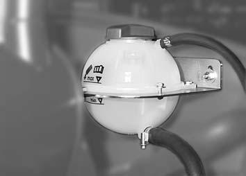
☞ Waitatleast10minutesafterswitchingofftheengine!
☞ Wearprotectiveglovesandclothing
☞ Alwaysstartbyactuatingthesafetyvalveinthecapoftheexpansiontank. Todothis: Openthecaptothefirstnotchandallowthepressuretoescape
☞ Proceedasfollows:
• Switchofftheengine
• Opentheenginecover
• Checkthecoolantlevelinthetransparentexpansiontank A IfthecoolantlevelisbelowMINmark B:
• Addcoolant–seeToppingupthecoolantlevel
AP0902 5–11 Maintenance
A D B C
Fig.141:Expansiontankforcoolant
Toppingupthecoolantlevel
WARNING!
Neveropenthecoolanttankandneverdraincoolantiftheengineiswarm, becausethecoolingsystemisunderhighpressureandthereisariskofburns
☞ Waitatleast10minutesafterswitchingofftheengine!
☞ Wearprotectiveglovesandclothing
☞ Alwaysstartbyactuatingthesafetyvalveinthecapoftheexpansiontank. Todothis: Openthecaptothefirstnotchandallowthepressuretoescape
☞ Proceedasfollows:
Aftertheenginehascooleddown:
• Reducetheoverpressureinexpansiontank A .Todothis: Openfillercap D byhalfarevolution
Afterreleasingthepressure:
• Openfillercap D completely
• FillupcoolantuptoMAXmark C
• Closefillercap D
Afterfillinginalargeamountofcoolant,e.g.firstfill:
• Starttheengineandletitwarmup
• Switchofftheengineandletitcooldown
• Checkthecoolantlevelagain
• Ifnecessary,addcoolantandrepeattheprocedureuntilthecoolantlevelremains constant
5.4.3Cleaningthecoolingfins
☞ Proceedasfollows:
• Switchofftheengine
• Opentheenginecover
• Blowcompressedairfromtheenginesidetoremovedirtfromthecoolingfins E.
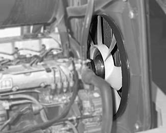
5–12 AP0902
Maintenance
A D B C
Fig.142:Expansiontankforcoolant
E
Fig.143:Cleaningthecooler
Important!
Donotcleantheairfiltercartridge.Theairfiltercartridgewillbedamagedifit iswashedorbrushedout!Dustonthecleansideofthefiltercausesacceleratedenginewear!
☞ Replacethefiltercartridgewhenthewarninglightcomeson!
☞ Neverreusedamagedfiltercartridges.Replacethemifyouareunsure!
☞ Ensurecleanlinesswhenreplacingthefiltercartridge!
WarningLight19/ 37 ontheinstrumentpanelmonitorsthefiltercartridge.Thefiltercartridgemustbereplaced:

• Ifwarninglight19/37 comeson,or
• Atthelatestafter1200servicehoursoronceeveryyear.
NOTE:
Theairfiltercanbefittedwithanoptionalsafetycartridgefor applicationsin especiallydustyenvironment.Itisnotpossibletocleanthesafetycartridge. Replacethesafetycartridgeeverythirdtimemaintenanceworkiscarriedout!
Important!
Thefiltercartridgemaydegradeprematurelywhenusedinacidicairforlong periodsoftime.Thisriskispresentforexampleinacidproductionfacilities, steelandaluminiummills,chemicalplantsandothernonferrous-metalplants.
☞ Useoptionalinductionsystemwhenworkinginanenvironmentwith increaseddust(option)
☞ Replacethefiltercartridgeandthe safetycartridge (option)asperwarning light19/37,orafter300servicehoursatthelatest!
☞ Cleandustvalve A regularlyaccordingtothemaintenanceplan!
AP0902 5–13 Maintenance 5
5.5Airfilter
A C
B D Maintenance
Fig.144:Airfilter
Maintenance
Functionalcheckofthedustvalve, everyweek
☞ Proceedasfollows:
• Switchofftheengine
• Opentheenginecover
• Compressthedischargeslotofdustvalve A
• Removehardeneddustbycompressingtheupperareaofthevalve
☞ Cleanthedischargeslotifnecessary
Important!
Donotcleantheairfiltercartridge.Theairfiltercartridgewillbedamagedifit iswashedorbrushedout!Dustonthecleansideofthefiltercausesacceleratedenginewear!
☞ Replacethefiltercartridgewhenthewarninglightcomeson!
☞ Neverreusedamagedfiltercartridges.Replacethemifyouareunsure!
☞ Ensurecleanlinesswhenreplacingthefiltercartridge!
☞ Replaceasfollows:
• Switchofftheengine
• Opentheenginecover
• Openthethreebowclips145/B onthelowerhousingsection145/C
• Removethelowerhousingsection145/C
• Removefiltercartridge146/E withaslightturningmovement
• Additionallyafterevery3rdreplacementofprimaryfiltercartridge E:
•Removesafetycartridge F (option),turningitslightlyasyoudoso
•Carefullyinsertthenewsafetycartridge F (option)intothetophousingsection
• Carefullyinsertfiltercartridge E intotheupperhousingsectiond145/D
• Putthelowerhousingsection145/C backintoplaceandsecurewith the3bowclips145/B
➥Thefilterelementisthenautomaticallypressedintothecorrectposition
• Putthelowerhousingsection144/Cbackintoplaceandsecurewith the3bowclips144/B
➥Thefilterelementisthenautomaticallypressedintothecorrectposition
5–14 AP0902
Replacingthefiltercartridge
A C
B D
Fig.145:Airfilter
308b1040.eps E
Abb.146:Removingthefiltercartridge
F E
Fig.147:Airfilterwithsafetycartridge(option)
5.6V-belt
WARNING!
Toavoidinjury,onlycheckorre-tension/replacetheV-beltwhentheengineis switchedoff.
☞ Switchofftheenginebeforecarryingoutmaintenanceworkintheengine compartment!
ChecktheV-belteverydayorevery10hoursofoperationandre-tensionitifnecessary. NewV-beltsshouldbere-tensionedafterabout15minutesofoperatingtime.
5.6.1CheckingtheV-belttension
☞ Checkasfollows:
• Switchofftheengine
• Preventthemachinefromrollingawayandremovetheignitionkey
• Opentheenginecover
• CarefullyinspecttheV-beltfordamage
IftheV-beltisdamaged:
☞ ReplaceV-belt
• Presswithyourthumbinthemiddleofthelongestsectionbetweentwopulleys(figure 148)tocheckwhethertheV-beltcanbedeflected,bynomorethanabout0.4in(10 mm)
• Re-tensiontheV-beltifnecessary–seeSection 5.6.2„Re-tensioningtheV-belt”
5.6.2Re-tensioningtheV-belt
☞ Re-tensionasfollows:
• Switchofftheengine
• Preventthemachinefromrollingawayandremovetheignitionkey
• Opentheenginecover
• Unscrewswivelscrews148/3 onthealternatorandthesetscrewon adjustmentbracket148/2
• UseasuitabletooltomovethealternatoruntilthecorrectV-belttensionisobtained
• Keepthealternatorinthisposition
• Firmlytightenswivelscrew148/3 onthealternatorandthesetscrewon adjustmentbracket148/2
• ChecktheV-belttensiononceagain.ChecktheV-belttensionagainafterthefirst25 servicehoursifanewV-beltismounted
AP0902 5–15 Maintenance
Fig.148:CheckingtheV-belttension
5.7Hydraulicsystem
5.7.1Specificsafetyinstructions
• Alllinescarryinghydraulicoilmustbedepressurizedpriortoanymaintenanceand repairwork.Todothis:
☞ Lowerallhydraulicallycontrolledattachmentstotheground
☞ Actuatethecontrolleversofthehydrauliccontrolvalvesseveraltimes
• Applytheparkingbraketopreventthemachinefromrollingawaybeforeyoucarryout serviceandmaintenancework
• Hydraulicoilescapingunderhighpressurecanpenetratetheskinandcauseserious injuries.Alwaysconsultadoctorimmediatelyevenifthewoundseemsinsignificant–otherwiseseriousinfectionscouldsetin!
• Ifthehydraulicoilinthelevelglassiscloudy,thisindicatesthatwaterorairhasentered thehydraulicsystem.Thismaycausedamagetothehydraulicpump!
☞ Contactyourdealerimmediately
• Insufficientorincorrecthydraulicoilwill resultindamagetothehydraulicsystem!For thisreason:
• Onlyuseauthorizedoilsofthesametype–see Enginefluidsandlubricants on page5-39
• Alwaystopupthehydraulicoilbeforethelevelgetstoolow
• Contactcustomerserviceifthehydraulicsystemfilteriscontaminatedwithmetal chippings.Otherwise,additionaldamagemayresult!
5.7.2Checkingthehydraulicoillevel
☞ Proceedasfollows:
• Parkthemachineonlevelground
• Retractallthehydrauliccylyinders
• Switchofftheengine
Whenalltheoilhasreturnedtothehydraulicoiltank:
• Opentheenginecover
• Checkthehydraulicoillevel149/Ainthesightglass:
5–16 AP0902 Maintenance
A ✓ Iftheoillevelis
IsvisibleinthesightglassOK
Belowthesightglass ☞ Topupthehydraulicoil
Abovethesightglass ☞ Drainthehydraulicoil
Fig.149:Oillevelsightglassonthehydraulicoiltank
•
•
•
5.7.3Toppingupthehydraulicoil
Donottopupthehydraulicoilunlesstheengineisswitchedoff.
☞ Topupasfollows:
• Parkthemachineonlevelground
• Retractallthehydrauliccylinders
• Switchofftheengine
• Applyparkingbrake16/25
Whenalltheoilhasreturnedtothehydraulicoiltank:
☞ Opentheenginecover
☞ Cleantheareaaroundbreatherfilter B ofthehydraulicoiltankwithacloth
☞ Openbreatherfilter B
Withthefilterinstalled:
☞ Topupthehydraulicoil
☞ Checkthehydraulicoillevelonoillevelsightglass A
☞ Topupthehydraulicoilifnecessaryandcheckagain
WARNING!
Draininghothydraulicoilandremovingthefilterelementcanbehazardous becauseoftheriskofburns
☞ Wearprotectivegloves
☞ Fitasufficientlylonghosetotheoildraincoupling
☞ Proceedasfollows:
• Parkthemachineonlevelground
• Lowerthetelescopicunitfully.Todothis:Pushlever16/21 forward
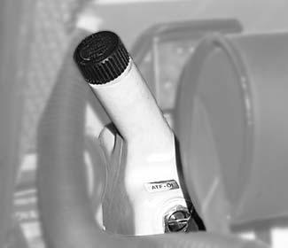
• Rollbackthebucketalltheway.Todothis:Pushlever16/21 totheleft
• Switchofftheengineandpreventthemachinefromrollingaway
• Opentheenginecover
• Removecover150/B ofhydraulicoiltank
AP0902 5–17 Maintenance
5.7.4Changingthehydraulicoil
B A
Fig.150:Hydraulicoiltank
Undertherearendofthemachine:
• Placeasuitablecontainertocollecttheoilasitdrains,withaminimumcapacity of15gallons(55liters)
• Removefillercap C oftheoildrainvalve
• Screwoildraincoupling D ontotheoildrainvalve,withasufficientlylonghose, makingsuretheendofthehoseisinthecontainer
➥Oildrainvalve E opensandtheoildrainsintothecontainer
• Flushoutthehydraulicoiltankwithasmallamountofhydraulicoil
• Removeoildraincoupling D onoildrainvalve E
• Screwonfillercap C oftheoildrainvalve
• Replacethehydraulicoilreturnfilter–see Hydraulicoilreturnfilter onpage5-20
• Checkthewhetherthefillingscreenisintact
Important!
Ifthehydraulicoiliscontaminated,thereisariskofseveredamageinthe hydraulicsystem.
☞ Alwaysaddhydraulicoilusingthefillingscreen!
• Fillthesystemwithfreshhydraulicoiluptothemiddle149/ A oftheoillevelsight glass
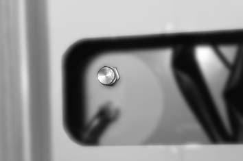
• Screwoncover150/B ofthehydraulicoiltank
• Starttheengine
Atalowenginespeed:
• Fullyextendtheliftandtiltcylindersonthetelescopicunit
• Turnthesteeringwheeltotheleftandrightseveraltimes,fromlocktolock
• Retractallthehydrauliccylindersagain
• Switchofftheengine
• Checkthehydraulicoillevelagainandtopupagainifnecessary
5–18 AP0902 Maintenance
C D E
Fig.151:Oildrainvalvewithcap
Importantinformationconcerningthe useofbiodegradableoil
• Useonlythebiodegradablehydraulicfluidsthathavebeenapprovedbythemanufacturer–see Enginefluidsandlubricants onpage5-39.Alwayscontactthemanufacturer fortheuseofotherproducts.Inaddition,asktheoilsupplierforawrittendeclarationof guarantee.Thisguaranteeisapplicabletodamageoccurringtothehydrauliccomponents,whichcanbeprovedtobeduetothehydraulicfluid
• Theremainingamountofinitialhydraulicfluidinthehydraulicsystemmustnotexceed 8%whenusinganothertypeofbiodegradableoil(manufacturerindications)
• Donottopupwithmineraloil–thecontentofmineraloilmustnotexceed2%inorder toavoidfoamingproblemsandtoensurebiologicaldegradability(hazardouswaste!)
• Whenrunningthemachinewithbiodegradableoil,thesameoilandfilterreplacement intervalsareusedasformineraloil–seemaintenanceplansintheAnnex. Inaddition,takeasampleofthehydraulicoilevery600servicehoursatthelatest,and haveitanalyzed(orderno.foroilsampleset:0004400014).Furtheractiondepends ontheresultsoftheoilanalysis
• Drainthecondensationwaterinthehydraulicoiltankevery600servicehours,andin anycasebeforethecoldseason.Thewatercontentshouldnotexceed0.1%byweight
• Theinstructionsinthisoperator’smanualconcerningenvironmentalprotectionalsofor theuseofbiodegradableoil
• Ifadditionalhydraulicattachmentsaremountedoroperated,usethesametypeof biodegradableoilfortheseattachmentstoavoidmixturesinthehydraulicsystem
Subsequentchangefrommineraloiltobiodegradableoil
☞ Completelyflushthehydrauliccomponents.Todothis:
• Parkthemachineonlevelgroundwhenitisatoperatingtemperature
• Retractallthehydrauliccylinders
• Switchofftheengine
Whenalltheoilhasreturnedtothehydraulicoiltank:
• Completelydrainthehydraulicoil
• Fillthehydraulicsystemwiththenewoiltype
• Starttheengine
• Operateallthecomponentsofthehydraulicsystem,suchascylinders,to“flush”the lines,cylindersandpumps
• Retractallthehydrauliccylinders
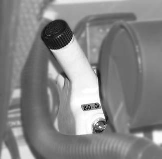
Whenalltheoilhasreturnedtothehydraulicoiltank:
• Switchofftheengine
• Completelydrainthehydraulicoilagain
• Replacethehydraulicoilreturnfilter(insert)–see Hydraulicoilreturnfilter on page5-20
• Fillthehydraulicsystemwithfreshoiltotherequiredlevel
• Checktheoillevelandtopupifnecessary
AP0902 5–19 Maintenance
Fig.152:Label:biodegradableoil
5.7.5Hydraulicoilreturnfilter
Theredwarninglight19/39 ontheinstrumentpanelmonitorsthefilter.Thefilterelement mustbereplaced:
• Ifwarninglight19/39 comesonwhenthehydraulicoilisatoperatingtemperature

• Atthelatestafter1200servicehoursoronceeveryyear.
Incoldweatherwarninglight19/39 maycomeonimmediatelywhentheengineisstarted. Thisisduetoincreasedoilviscosity.Inthiscase:
☞ Setenginespeedsothatthewarninglightgoesout
☞ Bearinmindtheinstructionsconcerningwarmup–seeWhentheenginehasstarted... onpage3-16
Changingthefilterelement
Important!
Contaminationmaycauseseveredamageinthehydraulicsystem!
☞ Takecaretoavoidcontaminationwhenworking!
☞ Proceedasfollows:
• Switchofftheengine
• Opentheenginecover
• Openbreather A onthehydraulicoiltank
• Unscrewcaps F and154/1 ofthefilterbyabout2turnsandwaitfortheoillevelinthe filterhousingtofalltothelevelinthetank
• Completelyunscrewandremovecovers F and154/1 ofthefilter
• Pulloutthefillerpipe154/2 withthefilterelement154/3,turningthemslightly
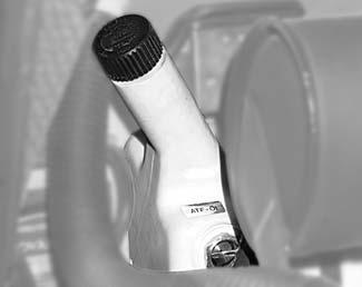
• Pullthefilterelement154/3 offthefillerpipe154/2 anddisposeofthefilterelement
• Checkthattheflatgasket154/4 onthefiltercap154/1 andtheO-ring154/ 5 onthe fillerpipeareingoodcondition
• FitnewO-ringsiftheoldonesaredamaged
• Slidethefillerpipe154/2 ontoanewfilterelement154/3 andinserttheassemblyinto thefilter
• Tightencaps153/F and154/1 byhand[Torque:15ft-lbs(20Nm)]
• Tightenbreatherfilter153/A byhand
• Carryoutatestrunofthehydraulicsystem
Withtheengineswitchedoff:
• Checkthefilterforleakage
5–20 AP0902 Maintenance
A F 308b1100.eps
Fig.153:Positionofhydraulicoilreturnfilter
2 1 2 3 4 5
Fig.154:Returnsuctionfilter:explodedview
5.7.6Replacingthebreatherfilter
Replacebreather A forthehydraulicoiltankevery1200servicehours,oratleastoncea year
☞ Proceedasfollows:
• Unscrewbreather A
• Screwinthenewbreatherfilter A
5.7.7Hydraulicpressurelines Specificsafetyinstructions
WARNING!
Useextracautionwhencheckinghydrauliclines,especiallywhensearching forleaks.Hydraulicoilescapingunderhighpressurecanpenetratetheskin andcauseseriousinjuries.Alwaysconsultadoctorimmediately,evenifthe woundseemsinsignificant–otherwise seriousinfectionscouldsetin!Never searchforleakswithyourbarehands,butwearprotectivegloves!Usepaper orwoodtocheckforminorleaks.Neveruseanunprotectedlightornaked flame!
☞ Alwaysobservethefollowinginstructions:
•Retightenleakingfittingsandhoseconnectionsonlywhenthesystemis notunderpressure;i.e.relievethepressurebeforeworkingonpressurizedlines!

•Neverweldorsolderfaultyorleakingpressurelinesandconnections. Replacedamagepartswithnewones!
•Whenreplacinghoselines,ensurethattheyarenottwisted!
• Leaksanddamagedlinesmustberepairedorreplacedasquicklyaspossible.Thisnot onlyincreasestheoperatingsafetyofthemachine,butalsohelpstoprotectthe environment
AP0902 5–21 Maintenance
A
Fig.155:Breatherfilteronthehydraulicoiltank
5.8Gearboxesandaxles
Maintenanceofthesecomponentsislimitedtocheckingtheoillevelsandtochangingthe oilatprescribedintervals–seemaintenanceplansintheAnnex.
NOTE: Onlyusenewsealingringsforoilfilleranddrainplugs.Drainoilonlyafterrunning themachineforalongperiodoftime!
5.8.1Rearaxletransfergearbox
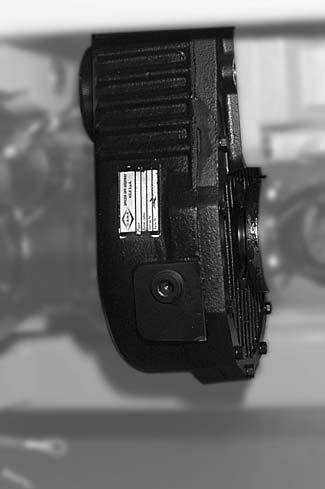
Checkingtheoillevel
☞ Proceedasfollows:
•Parkthemachineonlevelgroundwhenthegearboxisatoperatingtemperature
•Cleanandunscrewplug A ontransfergearbox B
Iftheoillevelisbelowtheopeningoriftheoillevelcannotbeseenatall:
•Topupwithoil –seesection5.15Enginefluidsandlubricants onpage5-39
Iftheoilleveliscorrect:
•Tightenplug A withanewsealingringtoensureanoil-tightseal
☞ Proceedasfollows:
•Parkthemachineonlevelgroundwhenthegearboxisatoperatingtemperature
•Cleanandunscrewplug156/A ontransfergearbox156/B
•Fillwithoiluntilitrunsoutofthefilleropening –seesection5.15Enginefluidsand lubricants onpage5-39
Ifthegearboxoillevelremainsconstant:
•Tightenplug156/A withanewsealingringtoensureanoil-tightseal
5–22 AP0902 Maintenance 5
A B C Maintenance
Fig.156:Rearaxletransfergearbox
Changingtheoil
WARNING!
Draininghothydraulicoilandremovingthefilterelementscanbehazardous becauseoftheriskofburns.
☞ Wearprotectivegloves
☞ Usesuitabletools,e.g.forunscrewingtheoildrainplug
☞ Proceedasfollows:
•Parkthemachineonlevelgroundwhenthegearboxisatoperatingtemperature
•Placeasufficientlylargecontainerunderthetransfergearboxtocollecttheoil
•Cleanandunscrewplug A ontransfergearbox B
•Unscrewplug C ontransfergearbox B
•Completelydraintheoldgearboxoil
•Tightenplug C withanewsealingringtoensureanoil-tightseal
•Fillwithoiluntilitrunsoutofthefilleropening –seesection5.15Enginefluidsand lubricants onpage5-39
Ifthegearboxoillevelissufficient:
•Tightenplug A withanewsealingringtoensureanoil-tightseal
Afterconductingatestrun:
•Checktheoillevelagainafterabout5minutes,andtopupifnecessary
AP0902 5–23
Maintenance
A B C
Fig.157:Rearaxletransfergearbox
Maintenance
5.8.2Frontandrearaxledifferentials
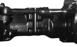
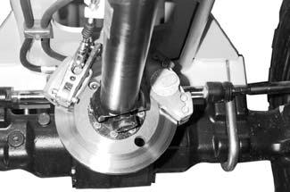
Environment!
Collectthedrainedgearoilinasuitablecontaineranddisposeofitbyanecologicallysafe method!
NOTE:
Onlyusenewsealingringsforoilfilleranddrainplugs.Drainoilonlyafterrunning themachineforalongperiodoftime!
Checkingtheoillevel
☞ Proceedasfollows:
•Parkthemachineonlevelground
•Cleanandunscrewplugs A
Iftheoillevelisbelowtheopeningoriftheoillevelcannotbeseenatall:
•Topupwithoil –seesection5.15Enginefluidsandlubricants onpage5-39
Iftheoilleveliscorrect:
•Tightenplug A withanewsealingringtoensureanoil-tightseal
Topuptheoillevel
☞ Proceedasfollows:
•Parkthemachineonlevelground
•Cleanandunscrewplug158/A
•Fillwithoiluntilitrunsoutofthefilleropening –seesection5.15Enginefluidsand lubricants onpage5-39
•Tightenplug158/A withanewsealingringtoensureanoil-tightseal
Changingtheoil
☞ Proceedasfollows:
•Parkthemachineonlevelgroundwhenitisatoperatingtemperature
•Placeadriptrayunderplug158/B tocollecttheoil
•Cleanandunscrewplug158/A
•Cleanandunscrewplug158/B
•Completelydraintheoldoil
•Tightenplug158/B withanewsealingringtoensureanoil-tightseal
•Fillwithfreshoilatopening158/A untilitrunsoutofthefilleropening –seesection5.15Enginefluidsandlubricants onpage5-39
•Tightenplug158/A withanewsealingringtoensureanoil-tightseal
5–24 AP0902
Rearaxle:againstthedirectionoftravel!
A B
Fig.158:Checkingtheoillevelonthefrontandrearaxle differentials
A B
Frontaxle:seeninthedirectionoftravel!
5.8.3Frontandrearaxleplanetarydrives
NOTE:
Fitnewsealingrings!Drainoilonlyafterrunningthemachineforalongerperiodof time!
Checkingtheoillevel
☞ Proceedasfollows:
•Parkthemachineonlevelground
•Turnplug A andoillevelmark B toahorizontalposition
•Cleanandunscrewplug A
Iftheoillevelisbelowopening C oriftheoillevelcannotbeseenatall:
•Topupwithoil –seesection5.15Enginefluidsandlubricants onpage5-39
•Tightenplug A withanewsealingring A toensureanoil-tightseal
Topuptheoillevel
☞ Proceedasfollows:
•Parkthemachineonlevelground
•Turnplug159/A andoillevelmark159/B toahorizontalposition
•Cleanandunscrewplug159/A
•Fillwithfreshoiluptotheoillevelmark159/2(overflow) –seesection5.15Engine fluidsandlubricants onpage5-39
•Tightenplug159/A withanewsealingring159/D toensureanoil-tightseal
Changingtheoil
☞ Proceedasfollows:
•Parkthemachineonlevelgroundwhenitisatoperatingtemperature
•Placeasuitablecontainerunderplug A
•Turnplug A tothetopmostposition
•Cleanandunscrewplug A
Never raisethemachineononesideonlyforthefollowingwork!
•Turnplug A tothelowestposition
•Completelydraintheoldoil
•Turnplug A andoillevelmark B toahorizontalposition
•Fillwithfreshoiluptooillevelmark B (overflow) –seesection5.15Enginefluidsand lubricants onpage5-39
•Tightenplug A withanewsealingring A toensureanoil-tightseal
AP0902 5–25 Maintenance
2 A
B C D 2 A
Fig.159:Checkingtheoillevelintheplanetarygear
B C D
Fig.160:Checkingtheoillevelintheplanetarygear
5.8.4Lubricatingtherearaxleoscillation-typebearing
NOTE:
Theoscillationbearinguses“Longlife”lubrication.Lubricatethebearingevery 1200servicehours(maintenanceplanC).
☞ Greaseoscillation-typebearing A ongreasenipple B withlithiumbasedmultipurpose grease–seesection5.15Enginefluidsandlubricantsonpage5-39
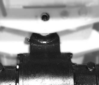
5–26 AP0902
Maintenance
Abb.161:Rearaxleoscillation-typebearing
B A
5.9Maintenanceofthebrakesystem
Environment!
Useasuitablecontainertocollectthebrakefluidasitdrainsanddisposeofitinanenvironmentallyfriendlymanner!
5.9.1Specificsafetyinstructions
• Brakesaretopprioritysafetycomponents.Incorrectworkcancausebrakefailure.For thisreason,allmaintenanceandrepairworkperformedonthebrakesmustbecarried outbytrainedpersonnel.Butthisdoesnotincludethefollowingactivities,whichmust beperformedbythedriverofthemachine:
• Dailycheckofthelevelinthebrake-fluidtank
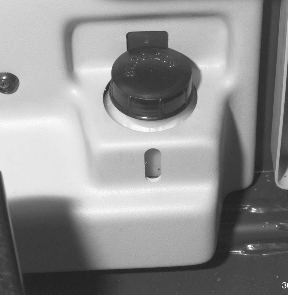
• Newbrakepadsneedrunninginiftheoptimumbrakingeffectistobeachieved.Torun inthebrakepads,brakethemachinemorefrequentlythanusualusingtheservice brakesbutavoidfullbraking!
• Replacedamagedbrakelinesorhosesimmediatelybecauseoftheriskofaccidents!
5.9.2Checking/toppingupbrakefluid
WARNING!
Maintainthebrakesystemproperly.Thesafetyofthebrakingsystemcanbe reducedbyimproperbrakefluidqualityorincorrectbrakefluidlevel–
☞ Checkthebrakefluidintank 4 atregularintervals
☞ Topupthebrakefluidtotheupperedgeofthesightglass
☞ ThebrakefluidmustcomplywiththeSAEspecification–see“Enginefluids andlubricants”onpage5-39
☞ Changethebrakefluideverytwoyears
Ifthefluidlevelisbelowtheupperedgeofthesightglass:
• Opentankcover A
• Topupthebrakefluidtotheupperedgeofthesightglass
AP0902 5–27 Maintenance
4 A MAX MIN
Fig.162:Checkingthebrakefluidlevelinthebrakefluid tank
5.10Telescopicunit
5.10.1Lubricatingthepivotpointsofthetelescopicunit
Ifmachineisinuninterrupteduse
☞ Lubricatethegreasenipples(circlesinfigure163) every10servicehour (ordaily) withgrease
Ifmachineisinoccasionaluse
☞ Lubricatethegreasenipples(circlesinfigure163) every50servicehours (oroncea week)withgrease
5.10.2Lubricatingthetelescopicunit
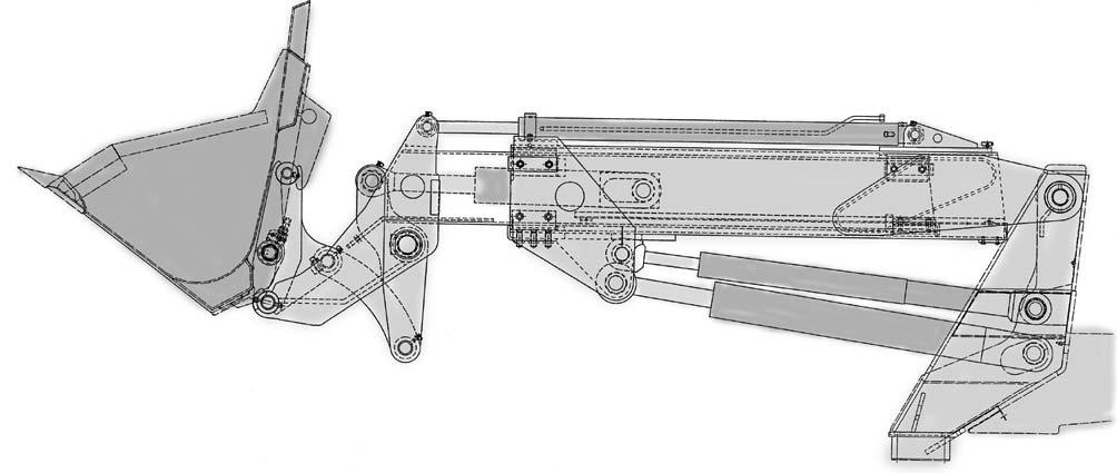
Lubricatethepadtracksatregularintervals. Recommendedlubricant–seesection5.15 Enginefluidsandlubricants onpage5-39
☞ Beforelubricating: Completelyextendthetelescopicunit
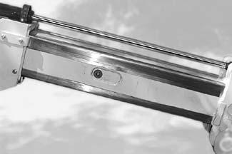
☞ Ifmachineisinuninterrupteduse
• Greasethepadtracksevery10hours
☞ Ifmachineisinoccasionaluse
• Greasethepadtracksonceaweek
5–28 AP0902 Maintenance
A B C D A B
Fig.163:Telescopicunitwithlubricationpoints
Fig.164:Wearpadsofthetelescopicunit
5.10.3Adjustingthewearpads
NOTE:
The(green)wearpadsarelocatedbetweentheinner163/C andouterboomsection163/D
Thewearpadscanbereadjustedastheyweardown–toaminimumthicknessof 0.25in(6mm)only–bymeansofsetscrews163/A and163/B.
Donotovertightenthesetscrews,otherwisethetelescopicunitisimpairedand doesnotworksmoothlyanylonger. Replacethewearpadsuponreachingorfallingbelowaminimumthicknessof 0.25in(6mm)!Inthiscasepleasecontactyourdealer.
☞ Adjustthewearpadsasfollows:
• Extendthetelescopicunitbyabout20cm,sothatthefrontwearpadscanbeeasily accessed
• Switchofftheengine
• Propthetelescopicunitsecurely
• Loosenthelocknutsatsetscrews163/A and163/B
• Firstaligntheinnerboomsection163/C horizontallywiththeouterboomsection163/ D .Todothis:
Screwinthesetscrews163A (hexagonsocket)
NOTE:
Screwinthesetscrewsuntilthewearpadstouchthepadtracksontheinner boomsection.Tightenthesetscrewbyturningitafurther1/4revolution.
• Firstaligntheinnerboomsection163/C horizontallywiththeouterboom section163/D .Todothis: Screwinthesetscrews163/B (hexagonsocket)
• Tightenthelocknutstosecureallsetscrews163A and B
AP0902 5–29 Maintenance
5.11Tirecare
WARNING!
Impropertirerepairsconstituteareapersonalinjuryhazard!
☞ Allrepairworkontiresandrimsmayonlybecarriedoutbyauthorizeddealers.
NOTE:
Regularinspectionofthetires
•Improvesoperatingsafety
•Increasestheservicelifeofthetires
•Reducesmachinedowntime
Refertothetableinsection“Specifications”onpage7-7fortheauthorizedtire typesandthecorrecttirepressures.Thistableisalsoonthelabelonthefrontwindow.
5.11.1Inspectionwork
Dailychecks
☞ Carryoutthefollowingmaintenanceworkdaily:
•Visualcheckofthetirecondition,especially:
•Tirepressure
•Outsideandinsidedamageoftiresandrims
•Wear
•Removeforeignbodiesfromthetiretread
•Removetracesofoilandgreasefromthetires
Weeklychecks
☞ Carryoutthefollowingmaintenanceworkeveryweek:
•Checkthetreaddepthofthetires
•Checkthetirepressure
5–30 AP0902
Maintenance
5.11.2Wheelchange
WARNING!
Useofwrongtiresorwheelscanbehazardous.
☞ Useonlythewheelsandtiresreleasedforyourmachine–seesection7 “Tires”onpage7-7
☞ Checkthewheelnutsfortightnessaftereverywheelortirechange
Important!
Thewheelsareheavyandcandamagethethreadsonthewheelstudsifthey arehandledincorrectly!
☞ Usesuitableassemblytools,suchascoveringsleevesforthestuds,ajack, etc.
Removingthewheels
☞ Proceedasfollows:
•Parkthemachineonlevelandfirmgroundandpreventitfromrollingaway.
•Slightlyloosenthewheelnutsofthetireyouwanttoremove.
•Placeajackundertheaxlebeam,makingsureitiswellsupported.
•Raisethesideoftheaxlefromwhichyouwanttoremovethetire.
•Checkthatthemachineiswellsupported.
•Completelyremovethewheelnuts
•Removethewheel
Installingthewheels
☞ Proceedasfollows:
•Placethewheelontothewheelstuds
•Tightenallthewheelnutspart-way
•Lowertheraisedaxle
•Tightenthewheelnutstotheprescribedtighteningtorque–seesection7.16.2 Specifictighteningtorques onpage7-9
AP0902 5–31 Maintenance
5.12Heating
Theheatingsystemofthemachineisequippedwithadustfilter,whichshouldbecleaned atregularintervalsandreplacedonceayear,asappropriate. Theheatingsystemislocatedontherightfrontofthecab.
5.12.1Cleaningthedustfilteroftheheatingsystem
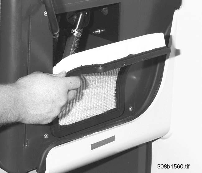
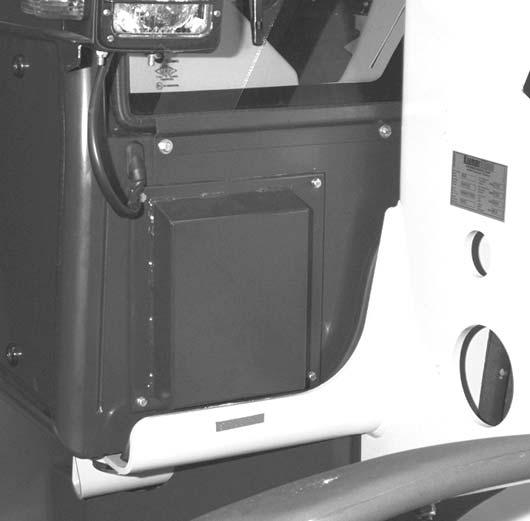
Adustfiltercleanstheairtakeninbytheheater.Blowcompressedairthroughthefilteras oftenasnecessary,butatleastonceayear.Thevolumeofwarmairflowingoutoftheair ventsdecreasesasfiltercontaminationincreases.
☞ Cleanthefilterasfollows:
• Removecover A atthefrontrightofthecabasfollows:
☞ Removescrews B
• Removedustfilter C
• Cleanorreplacedustfilter C
• Re-insertthecleaneddustfilterandinstallcover C
5–32 AP0902 Maintenance
B A
Fig.165:Replacingthecoveroftheheatingsystem
C
Fig.166:Replacingthedustfilteroftheheatingsystem
5.13Electricalsystem
5.13.1Specificsafetyinstructions
• Thebatterycontainssulfuricacid!Thisacidmustnotbeallowedtocomeintocontact withtheskin,theeyes,clothingorthemachine. Thereforewhenrechargingorworkingnearthebattery:
☞ Alwaysweargogglesandprotectiveclothingwithlongsleeves
Ifacidisspilled:
☞ Thoroughlyrinseallaffectedsurfacesimmediatelywithplentyofwater
☞ Thoroughlywashanypartofthebodytouchedbytheacidimmediatelywithplentyof waterandseekmedicalattentionatonce!
• Duringcharginginparticular,butalsoduringnormalbatteryoperation,anoxygen/ hydrogenmixtureisformedinthebatterycellswhichhasariskofexplosion!
• Donotattempttojump-startthemachineifthebatteryisfrozenoriftheacidlevelis low.Thebatterymayruptureorexplode!
• Avoidsparksandunprotectedlightsources,andrefrainfromsmokinginthevicinityof openedbatterycells,becausethegasproducedduringnormalbatteryoperationmay ignite!
• Useonly12Vpowersources.Highervoltageswilldamagetheelectricalcomponents
• Whenconnectingthebattery,ensurethatthepolesarenotreversed,becausesensitive electricalcomponentswillbedamaged
• Donotinterruptvoltage-carryingcircuitsatthebatteryterminals,becauseofthedanger ofsparking!
• Neverplacetoolsorothermetalitemsonthebattery,becauseoftheriskofshort circuit!
• Disconnectthenegativebatteryterminalbeforestartingrepairworkontheelectrical system
• Disposeofusedbatteriesproperly
5.13.2Serviceandmaintenanc eworkatregularintervals
AP0902 5–33 Maintenance
Beforedrivingthemachine ☞ Checkeverytimebeforedrivingthemachine: • IsthelightingsystemOK? Everyweek ☞ Checkeveryweek: • Cableandgroundconnections
Chafingonwiringharnesses
Conditionofthebatteryterminals
•
•
Maintenance
5.13.3Instructionsconcer ningspecificcomponents
Cables,bulbsandfuses
• Defectivecomponentsoftheelectricalsystemmustalwaysbereplacedbyauthorized technicians,exceptthatbulbsandfusesmaybechangedbyotherpersons
• Whencarryingoutmaintenanceworkontheelectricalsystem,payparticularattention toensuringgoodcontactinconnectionsandfuses
• Blownfusesindicateoverloadingorshortcircuits.Theelectricalsystemmusttherefore becheckedbeforeinstallingthenewfuse
• Onlyusefuseswiththespecifiedcapacity(amperage)–see Electricalsystem on page7-5
Alternator
Alwaysobservethefollowinginstructions:
• Onlytesttheenginewiththebatteryconnected
• Whenconnectingthebattery,ensurethatthepolesarenotreversed
• Alwaysdisconnectthebatterybeforecarryingoutweldingworkorconnectingaquick batterycharger
• Replaceadefectivechargewarninglightasquicklyaspossible
Battery
NOTE: Thebatteryislocatedintheenginecompartment,ontheleftside. Evenso-called“maintenance-free”batteriesmustundergomaintenance,because theytooconsumewater. Alwaysfollowthespecificsafetyinstructions!
☞ Observethefollowinginstructionstoensurealongbatteryservicelife:
• Keepthesurfaceofthebatteryincleananddrycondition
• Checktheacidlevelatregularintervalsandifnecessary,fillupwithdemineralizedor distilledwater.Neverfillupwithacid!
Checktheregulatorvoltageofthemachineincaseofincreasedlossofwater
• Donotuseso-calledbatteryimprovingcompounds
• Checkthebatterychargeconditionbymeasuringtheaciddensity. (Exception: Inthecaseofclosedbatteriesbymeasuringtheoff-loadvoltage)
NOTE:
Rechargethedisconnectedbatteryifspecificgravityisbelow1.21.Atthislevelthe batterywillfreezeonlyattemperaturesbelow5°F(–15°C).
5–34 AP0902
Driveelectronics
Checkingthebatterychargecondition
☞ Checkthebatterychargeconditionasfollows:
• Parkthemachineonlevelground
• Switchofftheengine
• Opentheenginecover Afterremovingthebatterycaps:
• Measurethespecificgravitywiththehydrometer
Instructionsforrechargingthebattery
• Avoidsparksandshortcircuits
• Removethebatteryforrecharging.Ifthebatterymustrechargedinthemachine, alwaysdisconnectthebatteryleadsunderallcircumstances
• Unscrewthebatterycaps(Exception:Closedbatteries)
• Switchoffthebatterychargerbeforeconnectingthebattery!
• Chargebatterieswithdirectcurrentonly.Connectthepositive(+)terminalofthe batterytothepositive(+)terminalofthebatteryrecharger,andthenegative(–) terminalofthebatterywiththenegative(–)terminalofthebatterycharger
• Recommendedchargingcurrent:onetenthoftheamphourcapacity(e.g.,80Ah=8A chargingcurrent)
• Chargeclosedbatterieswithregulatedbatterychargersonly
• Makesureacidtemperaturedoesnotexceed120°F(55°C)duringrecharging.Stop rechargingthebatteryifthetemperaturerisesanyfurther. Thebatteryisfullychargedifspecificgravityandchargingvoltagedonotriseany furtherwithin2hours
• Rechargingclosedbatteriestakesatleast12to16hours,andisnotcompletedunless off-loadvoltageis ≥ 12.8Vseveralhoursafterrecharging
• Checktheacidlevelafterrechargingandifnecessary,fillupwithdemineralizedor distilledwateruptothemaximumacidlevelmarkor0.6inch(15mm)abovethebattery plates.Neverfillupwithacid!
• Donotopenclosedbatteries.Neveraddwater
Instructionsfortemporarystorageofthemachine
• Ensurefullbatterycharge(seeabove)
• Ifthebatteryremainsinthemachine,disconnectthenegative(–)terminal
• Checkthebatterychargeconditionatregularintervals(seeabove)
• Removethemainplugwhencarryingoutweldingwork,etc.
AP0902 5–35
Maintenance
Maintenance
5.14Generalmaintenancework
5.14.1Cleaning
Cleaningthemachineisdividedinto3separateareas:
• Insideoftheoperatorcompartment
• Exteriorofthemachine
• Enginecompartment
Thewrongcleaningequipmentandchemicalsmayimpairtheoperatingsafetyofthe machineandaffectthehealthoftheperson(s)cleaningthemachine.Itisthereforeessentialtoobservethefollowinginstructions.
Generalinstructionsforalltheareas
ofthemachine
Washingsolvents
• Ensureadequateroomventilation
• Wearsuitableprotectiveclothing
• Donotuseflammableliquids,suchasgasolineordieselfuel
Compressedair
• Workcarefully
• Weargogglesandprotectiveclothing
• Donotaimthecompressedairattheskinoratotherpeople
• Donotusecompressedairforcleaningyourclothing
Whenusingahigh-pressurecleanerorsteamcleaner
• Electricalcomponentsanddampingmaterialsmustbecoveredandnotdirectly exposedtothejet
• Covertheventfilteronthehydraulicoiltankandthefillercapsforfuel,hydraulicoiletc.
• Protectthefollowingcomponentsfrommoisture:
• Engine
• Electricalcomponents,e.g.,alternator,plugandsocketconnectionsetc.
• Controldevicesandseals
• Airfilters,etc.
Whenusingvolatileandeasilyflammableanticorrosionchemicalsandsprays:
• Ensureadequateroomventilation
• Donotuseunprotectedlightsoropenflames
• Donotsmoke!
5–36 AP0902
Insidetheoperatorcompartment
Important!
Neverusehigh-pressurecleaners,steamcleanersorhigh-pressurewaterto cleantheinsideoftheoperatorcompartment.Waterunderhighpressuremay •Penetrateintotheelectricalsystemsandcauseshortcircuitsand •Damagesealsanddisablethecontrols!
Forcleaningtheoperatorcompartment,werecommendusingthefollowingaids:
• Broom
• Vacuumcleaner
• Dampcloth
• Bristlebrush
• Bucketofwater
Cleaningyourseatbelt
• Cleantheseatbelt(whichremainsfittedinthemachine)onlywithamildsoapsolution; donotusechemicalagents,becausetheymaydestroythefabric!
WARNING!
Forautomaticseatbelts(option),soiledbeltsmayimpairwindingandthereby affectsafety.Onlywindseatbeltwhenitisdry!
Exteriorofthemachine
Enginecompartment
Thefollowingarticlesaregenerallysuitable:
• High-pressurecleaneror
• Steamcleaner
WARNING!
Toavoidinjury,cleantheengineonlywhenitisstopped.
☞ Switchofftheenginebeforecleaning
Important!
Whencleaningtheengineusingawaterjetorsteamcleaner,donotpointthe jetdirectlyatelectricalmeasurementsensorssuchastheoilpressureswitch, becauseotherwise,liquidpenetratingsuchunitscanleadtocorrosionand failureofthemeasuringfunction!
AP0902 5–37 Maintenance
5.14.2Boltedconnections
Allboltedconnectionsmustbecheckedregularly,eveniftheyarenotlistedinthemaintenanceschedules.
Tightenlooseconnectionsimmediately.Tighteningtorquescanbefoundinsection “Specifications”.
5.14.3Pivotsandhinges
Allmechanicalpivotpointsonthemachine(e.g.doorhinges,joints)andfittings(e.g.door holders)shouldbelubricatedregularly,eveniftheyarenotlistedinthelubricationplan.
5–38 AP0902 Maintenance
5.15Enginefluidsandlubricants
Component/
Dieselengine Engineoil2
HD-C5W-303
-4°Fto+86°F (-20°Cto+30°C)
HD-C10W-30 14°Fto+95°F (-10°Cto+35°C)
HD-C10W-40;EO1040B5
14°Fto+104°F (-10°Cto+40°C)
HD-C15W-40;EO1540B 5 32°Fto+104°F (0°Cto+40°C)
7.4quarts (7litres) 4
Rearaxletransfergearbox
SAE80W-90 1.6quarts (1.5litres) Planetarydrives–leftandright frontandrearaxle
Gearboxoil6
SAE90LS 3.9quarts (3.7litreseach)
0.7quarts (0.7litreseach) Differential–frontandrearaxle
SAE5W/303
-4°Fto+95°F (-20°Cto+35°C)
SAE10W/30 14°Fto+104°F (-10°Cto+40°C)
SAE10W/40;EO0540B5
SAE15W/40;EO1540B5 32°Fto+104°F (0°Cto+40°C)
Hydraulicoiltank
About52.8quarts (50litres)
ATF ATF66M/ATF86(ATF5) 14°Fto+86°F (-10°Cto+30°C)
Biodegradableoil
GreasenipplesMultipurposegrease
WearpadsofthetelescopicunitMultipurposegrease
Mountingofpins,shaftsetc.Speciallubricatinggrease
AVILUBSyntofluid46
PANOLINHLPSynth46
FIATIdraulicarBS68
AGIPArnicaS68
Lithium-saponifiedbrand-namegreases
MPG-A5 Year-roundAsrequired
1.Thecapacitiesindicatedareapproximativevalues;theoillevelcheckaloneisrelevantforthecorrectoillevel
2.MIL-L-2104C;APICD/CE/CF4;CCMC-D4
3.Onlywithoilpreheating
4.Withfilterchange
5.Abbreviationforlubricants(HauptverbandderDeutschenBauindustriee.V.–Germanconstructionengineeringassociation)
7.NecessaryadditionofFuchsLSconcentrate:20gr/ltr.
8.250grtube:orderno.:0004413210
AP0902 5–39 Maintenance 5
Engine/machinefluid SAEgrade Specification Season/ temperature Capacities1
application
6.MIL-L-2105B;API-GL5;ZFTE-ML-0.5 Year-round
SAE80W-90+LSconcentrate7
Engineoil2
Year-roundAsrequired BatteryterminalsAcid-proofgrease SP-B5 Year-roundAsrequired
Optimolypaste“TA”8
Year-roundAsrequired FueltankDieselfuelDIN51601,min45Cetan, 15.9gal (60ltr) Brakesystem BrakefluidSAEJ1703DOT3.4,SP-A5 RadiatorCoolant Water+antifreeze;SP-C5 Year-round About9.0quarts (8.5litres) WashersystemCleaningagentWater+antifreeze About1.3quarts (1.2litres) Maintenance
5.16Maintenancekits
5–40 AP0902 Maintenance
Maintenancekits PartnumberDescriptionQtyRemarks Maintenancekitfor“1stInspection” 0160030030Maintenancekit 1 MaintenancekitforMaintenanceplan“B” 0160030130Maintenancekit 1 MaintenancekitforMaintenanceplan“C” 0160030230Maintenancekit 1
0000805573Filterforheater1(notincludedinmaintenancekit)
Additionalpartsformaintenancekits 0000805188Airfilter1(option,notincludedinthemaintenancekit)
Section6 Helpfulinformationforusingtheservicepartslist
6.1Introduction
Thisoperator’smanualandaseparateservicepartslisthavebeenhandedovertoyou togetherwithyourmachine.
Pleasereadthissectioncarefully.Itwillmakeiteasierforyoutocarryoutyourworkand findserviceparts.
Theillustrationsintheservicepartslistarenotbindingfordesign. Subjecttofurtherdevelopment andtechnicalmodifications.
6.2Compositionofservicepartslist
6.2.1Groups
Theservicepartslistisdividedinfunctionalgroups. Groupsareidentifiedbynumbers(e.g.01=engine)
AP0902 6-1 Helpfulinformationforusingtheservicepartslist 6 6Helpfulinformationforusingtheservicepartslist
01
Group
Fig.167:Titlepageofagroup
6-2 AP0902
6.2.2Groupoverview Theservicepartslistcontainsthefollowinggroups: Group Description 01 Engine 08 Fuelsystem 10 Airfilter 15 Coolingsystem 17 Speedregulation 20 Machineframe 22 Hydrostaticdrive 23 Frontaxle 24 Brakesystem 26 Rearaxle 27 Steering 29 Operator'sseat 30 Sheet-metalparts 31 Wheelsandtyres 32 Exhaustsystem 33 Electricalsystem 34 Cab 36 Hydraulicsystem 41 Heatingandventilation 41/3 Buckets 41/4 Palletforks 43 Tools,labels A Numberindex
Helpfulinformationforusingtheservicepartslist
6.2.3Figures
Groupsconsistofoneormorefigures.Theyareidentifiedattheupperrightbythefigure number.
Thenumberbeforethehyphenidentifiesthegroup(e.g.01).
Thereferencenumbersinthefiguresidentifytheindividualserviceparts.Thecorrespondingpartnumbersarelistedinthenumberindex.
Thefiguresarereducedrepresentationsofassembliesandcomponentparts,andarenot bindingfordesign.
Subjecttofurtherdevelopment andtechnicalmodifications.
6.2.4Numberindex
Thenumberindexisincludedattheendoftheservicepartslistandcontainsallpartnumberscorrespondingtothereferencenumbersinthefigures.Partnumbersarelistedinthe orderoffigures,andofreferencenumber.
AP0902 6-3
Helpfulinformationforusingtheservicepartslist
01-58 20 19 17 18 21 22 21 19
Figurenumber
Fig.168:Exampleforfigure 01-7.......1..... 7571646012 01-7.......2..... 7578646001 01-7.......3..... 7578646002 01-7.......4..... 0003330367 01-7.......5..... 7571646041 01-7.......6..... 7571646042 01-7.......7..... 7571646043 01-7.......8..... 7578646011 01-7.......9..... 7578646012 01-7.......10.... 7578646013
Referencenumbers 01-7........11....7579641081 01-7........12....7579641082 01-7........13....7579642051 01-7........14....7577646040 01-7........15....7577646036 01-7........16....0003333065 01-7........17....0003332965 01-7........18....0003335166 01-7........19....0003334866 01-7........20....7572642006
08-1.......1..... 7572642012 08-1.......2..... 7572642052 08-3.......1..... 7572642502 08-3.......2..... 7572646515 08-3.......3..... 7572642510 08-3.......4..... 7572642505 08-3.......5..... 7572646517 10-1.......1..... 0003330256 10-1.......2..... 0003338266 10-1.......3..... 0003336265
23
2 1234567890 00-2 23
2 1234567890 00-2 23
2 1234567890 00-2
Figure
Referencenumber Partnumber
Fig.169:Detailofnumberindex
6.3Symbolsandabbreviations
Symbolsandabbreviationsareusedinthefiguresforclearidentificationofparts.Combinationsofsymbolsandabbreviationsarealsoused.
6.3.1Descriptionofsymbols
Symbolsmayhavethefollowingmeanings:
Identifiesacomponentpart.
Thecirclednumberidentifiesanassemblywhichmayconsistofseveralcomponent parts.
Assembliesaredeliveredasfinishedassemblies,orpreassembledwithallnecessary componentparts.
Componentpartscanbegroupedinbracketsorinboxes,orappearbelowthereference numberoftheassembly,e.g.referencenumbers18and19.
Acomponentpartcanconsistofseveralpartswhichmaybedeliverableasawholeonly, e.g.referencenumber19.
Componentpartsgroupedinabox,withoutreferencenumberfortheassembly,identify details.
6-4 AP0902
Helpfulinformationforusingtheservicepartslist
Symbol Description Referencenumber
22 17 20 19 17 18 21 22 21 19 1 3 4 5 6 2 8 10 11 12
Validity
➜❙
➜❙
❙➜
❙➜
Instructionsforassembly
Partsarevalidonly uptoandincluding the serialnumber stated,e.g.uptoandincludingserialnumber307630238
Partsarevalidonly uptoandincluding the identificationnumber statedforthe respectiveassembly,e.g.uptoandincludingcabnumber0237.Thiscanalsoinclude othersymbols,e.g.axle,engineetc.
Partsarevalidonly startingandincluding theserialnumberstated,e.g.startingand includingserialnumber307630239
Partsarevalidonly startingandincluding theidentificationnumberstatedforthe respectiveassembly,e.g.startingandincludingcabnumber0237.Thiscanalsoinclude othersymbols,e.g.axle,engineetc.
Symbolforaxle
Symbolforcab
Symbolforengine
Donotremoveparts,partscannotberepaired
Tightenpartswithatorquespannertotheprescribedtorque.Usestandardtorquesifno specifictorqueisstated–seesection7.16.1 Generaltighteningtorques onpage7-9and section7 “Specifictighteningtorques” onpage7-9
Safetypart!
Forreasonsofsafety,partsmaybedismantledorrepairedbyqualifiedmechanicsonly. Otherwisepartsmustbereplacedasawhole!
Checkpartsforwearbeforereassembly,e.g.bearings,rotaryshaftlipsealsetc.
Partsarenotreuseableandmustbereplacedduringrepairwork,e.g.sealingelements Payspecialattentiontodirectionofinstallationwhenremovingorfittingparts,e.g.rotary shaftlipseals,bearings,bushingsetc.
Usesecuringmeansandsealingcompoundsstated,e.g.Loctite242 Measurelength/thicknessofnewpart,e.g.shims,edgeguards,sealingstripsetc. Rounduptothefullmetreforordersbythemetre!
Measurethicknessofnewpart,duetoavailabilityinvarioussizes. Statealldimensionsinmm(millimetres).
Specialsymbols Symbolforspecialversionwithfloatposition
AP0902 6-5
Helpfulinformationforusingtheservicepartslist
Symbolforhydrauliccylinder Symbolforsealingkit Symbolfortoolkit Symbolfordocumentation
6 7 8 0.15 0.2 0.5
Symbol Description
Helpfulinformationforusingtheservicepartslist
6.3.2Abbreviations
Indicationofposition
Abbreviationsspecifypositionofserviceparton/inmachineindrivingdirection. Combinationsofabbreviationsarealsopossible,e.g. HLO (upperrearleft).
Application
Abbreviationsspecifyuseofserviceparton/inmachine.
6.4Machinedata
Alwaysincludetheexactmachinedatainyourorderstoensurecorrectdeliveryofservice partsrequired.
Seesection1 “Machinedata” onpage1-6and “Typelabelsandcomponentnumbers” on page1-7fortherelevantmachinedata.
6-6 AP0902
Abbreviation Description F Front H Rear L Left R Right O Upper U Lower M Centre A Outer I Inner Abbreviation Description BA Specifiesoperator’smanual ET Specifiesservicepartslist De German En English Fr French MC Specifiesmicrofiches SO Specifiesspecialequipment
6.5Helpfulinformationfororderingserviceparts
Deliveryofservicepartscashondelivery. Damagedsampleswillbescrappedifnorequestforreturnhasbeenforwardedwithin4 weeks.
ServicepartscanbereturnedonlyuponagreementwithourServicePartsDepartment. Returnexcludes:
Seals,O-rings,sealingkits,electricalparts,specialpurchasesandpartsorderedwithout exactmachinedata.
6.5.1Orderinformation
Alwaysincludethefollowinginformationinyourorderstoensurecorrectdelivery ofserviceparts:
• Customerandaddress
e.g.JasonMiller
HighStreet40
LeightonBuzzardLU58RT
• Deliveryaddress ifnotidenticalwithcustomer'saddress
e.g.Constructionsite:JeffMason
ChurchStreet41
HighWycombeHP93ER
• Modeofshipment
e.g.UnitedParcelService(UPS)
Shipmentwillbemadeatourowndiscretionifnoindicationsaremade
• Machinedescription
e.g.418T
• Modelandserialno. (seetypelabelonmachine)
e.g.418T,418T0239
• Servicepartslistandedition (seeservicepartslistcover)
e.g.EditionA
• Figure,reference (inservicepartslist)
e.g.01-8,reference15
• Partnumber (innumberindexinservicepartslist)
e.g.:0000801987
• Quantityandunit
e.g.1off
• Forcomponent,identificationnumber (seetypelabel)
e.g.engine:KubotaV1305–073248
AP0902 6-7
Helpfulinformationforusingtheservicepartslist
Helpfulinformationforusingtheservicepartslist
6.5.2Addressforyourservicepartorder
GehlCompany
143WaterStreet
WestBend,WI53095-0179
U.S.A
Telephone:262-334-9461
Fax:262-338-7517
6-8 AP0902
Specifications 7
Section7
7Specifications
7.1Frame
7.2Engine
Sturdysteelsheetframe,rubber-mountedengine
Engine Product
Perkinsdieselengine
Model 704-30DI
Design Vertical,water-cooled4-strokedieselengine
No.ofcylinders 4
Displacement 180in³(2955cm³)
Boreandstroke
Compressionratio
3.8x3.9in(97x100mm)
1:17.5
Output(asperISO9249) 58hp(43.1kW)at2400rpm
Max.torque 154.9lb-ft(210Nm)at1600min-1
Specificminimumfuelconsumption 288g/hp-hr(215g/kWh)
Fuelinjectionsystem
Directfuelinjection
Firingorder 1–3–4–2
Startingaid Glowplug
Max.inclinedposition(engineno longersuppliedwithoil):
25°inalldirections
Observetiltinglimitofthemachine!
Oilpressure 61lb/in2 (4.2bar)
Valvetipclearance
Intake,exhaustvalve 0.01in(0.35mm),engineatcoldtemperature respectively
Exhaustemissionsvaluesasper ISO/TR14396
EC97/68level1
US40CFRpart89
AP0902 7–1 7
Specifications
7.3Powertrain
Variabledisplacementpump
Design Axialpistonpump(swashplatedesign)
Displacement 0–2.5in³/rev(0–41cm³/rev)
Max.operatingpressurep 5584lb/in2 (385bar) StartingRPMs 1050 ±50
Droop 2250 ±50
Boostpump(integratedinvariabledisplacementpump)
Design Internalgearpump
Displacement 0.7in³/rev(11cm³/rev)
Charging/boostpressure 290lb/in2 (20bar) Control
7.4Axles
Drivingdirection
Forward–reverseoncontrollever Inching Electrically(potentiometer)
Variabledisplacementmotor
Design Axialpistonmotor(swashplatedesign) Capacity 0.9–3.7in³/rev(16–60cm³/rev
Drivespeed 0–12mi/h(0–20km/h),forwardandreverse Max.tractionforce 8543lbf(38kN)
Frontaxle(withself-lockingdifferential40%)
Rearaxle(with40%differentiallock)
1.Withstandardtyres12.5–20
7–2 AP0902
Specifications
Design Rigidsteeringanddriveaxle King-pininclination 6° Camber 0° Positive/negativewheelcastorSteeringangle 40° Toe-in 0in(0mm) Trackwidth 54in(1370mm)1
Design
King-pininclination 6° Camber 0° Totaloscillation +/-8.5° Positive/negativewheelcastor –Steeringangle 40° Toe-in 0mm Trackwidth 54in(1370mm)1
Steeringanddriveaxle,oscillating
7.5Brakes
Servicebrake
DesignFoot-operated,hydraulicdiscbrake+hydrostat
MountedinFrontaxle,drive(rearaxle)
EffectOnbothaxlesviacardanshaft
BrakefluidSeeEnginefluidsandlubricants
Parkingbrake
DesignManual,mechanicaldiscbrake
MountedinFrontaxleinput
EffectOnbothaxlesviacardanshaft
7.6Steering
Steering Design
7.7Workhydraulics
Hydrostaticfour-wheelsteeringwithemergency steeringfeatures(closedversion)
Steeringmode Fourwheelsteering
Assemblies
Hydraulicpump,steeringunitwithflangedpriority valve,steeringcylinder,automaticsynchronizationinleftandright-handfinalpositions
Max.pressureofhydrauliclines 2611lb/in2 (180bar)
Hydraulicpump Gearpump Displacement1.4in³/rev(23cm³/rev)
Workhydraulics
Hydraulicpump Gearpump Displacement 1.4in³/rev(23cm³/rev)=17g/min(66l/min) at2400rpm
Controlvalve 3sections
Max.servicepressure 3046+10 lb/in2(210 +10 bar)
Secondarypressurelimiting Secondarypressurereliefvalvefortiltram: rodside3481lb/in2(240bar) bottomside1450lb/in2(100bar)
Secondarypressurereliefvalveforliftram: bottomside3481lb/in2(240bar) Filter Returnsuctionfilter(7.3lb/in2 (0.5bar)initial stress)
Hydraulicoiltank 13.2gal(50l)
AP0902 7–3 Specifications
7.8Telescopicunit
7–4 AP0902 Specifications
Telescopicunitwithbucket 1, 2 1.Withstandardtyres12.5-20 2.Standardbucket810136 Telescopicunit BucketcapacityheapedasperISO 1.1yd³ (0.85m³) Tippingload 6557lb (2974kg) Payload 3278lb (1487kg) Liftloadatmax.height 6173lb (2800kg) Bucketwidth 69in (1750mm) Lengthoftelescopicextension 45in (1150mm) DumpheightwithstandardbucketRetracted 118in (3000mm) Extended 158in (4000mm) Fulcrumheightofquickhitchfacility 185in (4690mm) DumpingreachExtended 47in (1205mm) Scrapingdepth about2in (50mm) Tilt-backangle 40° Dump-outangle 40° Breakoutforce(liftcylinder) 6744lbf (30.0kN) Breakoutforce(tiltcylinder) 11015lbf (49.0kN) Forkarms3 (payloadsstatedfor20in(500mm)loaddistance) 3.Palletforks810135 Tippingload(ISO8313)Retracted 4982lb (2260kg) Payload(ISO8313) Extended(S=1.254) 4.Onfirmandlevelground 2425lb (1100kg) Extended(S=1.675) 5.Off-road 1808in (820kg) Retracted(S=1.254) 3968lb (1800kg) Retracted(S=1.675) 2965lb (1345kg) PalletheightRetracted 136in (3450mm) Extended 177in (4500mm) Movablepayloadintransportposition(S=1.254) 4850lb (2200kg)
7.9Electricalsystem
Alternator
Starter
12V/65A
12V/2.5kW
Battery 12V/80Ah
Socket E.g.forcigarettelighter;15Amax.
Thefuseboxesarelocatedinthesideconsoleinthecab.
–Instrumentlighting
F1A7.5A
–Brakelights
F2A7.5A –Horn
–Wiper/washsystem
F3A10A –Heater
F4A7.5A
–Cutoffsolenoid
–Rearwiper
F5A10A –Frontwiper
F6A10A –Cigarettelighter
F7A7.5A –Interiorlighting
–Hazardwarningsystem
F8A7.5A –Switchlights
F9B10A
30864b0030.eps
–Turnindicators
–Driveswitch
–Driveelectronics
F10B15A –Lights
F11B7.5A –Highbeam(right)
F12B7.5A –Highbeam(left)
F13B7.5A –Lowbeam(right)
F14B7.5A –Lowbeam(left)
F15B7.5A
–Parkinglight(right)
–Rearlight(right)
F16B7.5A –Parkinglight(left) –Rearlight(left)
F17C10A
–Air-suspensionseat(option)
F18C7.5A –Telescopicunit
F19C7.5A
F20C7.5A
–Lockforquickhitchfacility(option) –Attachments(option)
–Notassigned
F21C25A –Workinglight(option)
F22C7.5A
–Rotatingbeacon(option)
C7.5A –Notassigned(spare)
C10A –Notassigned(spare)
AP0902 7–5 Specifications
7.9.1Fuseboxesinsideconsole
Fig.170:Fuseassignmentinsideconsole
50
A B C A
Fuse Row Ratedcurrent(A) Protectedcircuit
7.9.2Mainfusesinenginecompartment
Themainfusearelocatedabovethehydraulicoiltank,underneathcover D
Fuse Ratedcurrent(A) Protectedcircuit
F23100A –Mainfuse
F24100A –Mainfuse
7.9.3Relays
RelaysK1andK2arelocatedabovethehydraulicoiltank,underneathcover D RelaysK2toK9arelocatedunderneaththecoverplateontherightsideofthecab,inthe sideconsole.
Description Function
K1 Switchingrelay,cutoffsolenoid
K2 Switchingrelaypreheating
K3 Switchingrelaydriveinterlock
K4 Switchingrelaylowbeam
K5 Switchingrelayhighbeam
K6 Switchingrelay,retracttelescopicunit
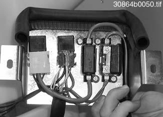
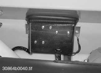
K7 Switchingrelay,extendtelescopicunit
K8 Hazardlightindicator
0160081701.eps
7–6 AP0902
Specifications
D
Fig.171:Mainfusesinenginecompartment
F24 F23
Fig.172:Relayassignment
K2 K1
K8 K5 K4 K3
K6 K7
7.10Tires
Bearinmindthestickeratthefrontwindowofthemachine!
Tyresize Tirepressure1
Specifications
7.11Weights
Weights1
7.12Noiselevels
Important!
NoisemeasurementcarriedoutinaccordancewithECguidelines86/662EEC (dynamic),79/113EECatmaximumenginespeed.Thesurfacewherethemeasurementswerecarriedoutwasasphalted.
AP0902 7–7
Wheelrims FrontRearWheelrimWheeloffset 12.5-20MPT10PR 36lb/in2 (2.5bar) 29lb/in2 (2.0bar) 11x200mm 14.5-20MPT10PR 29lb/in2 (2.0bar) 25lb/in2 (1.7bar) 375/75R20136G 36lb/in2 (2.5bar) 29lb/in2 (2.0bar) 405/70R18141B
1.Increasetyrepressureby0.5barduringpalletforksoperation!
2
44lb/in2 (3.0bar) 36lb/in2 (2.5bar) 13x180mm 12.5-20MPT10PR 36lb/in2 (2.5bar) 29lb/in2 (2.0bar) 11x200mm
2.Overallwidthofmachinelargerthanstandardbucketwhenequippedwiththesetyres
Kerbweight 10913lb(4950kg) Frontaxleload 3968lb(1800kg) Rearaxleload 6945lb(3150kg) Grossweightrating 13228lb(6000kg) Frontaxleweightrating 8267lb(3750kg) Rearaxleweightrating 8267lb(3750kg) Max.authorizedloadfortowingfacility None Noiselevels Soundpowerlevel 99dB(A) Noiselevelinthecab 74dB(A)
1.Withstandardbucket810136andstandardtyres12.5-20
7.13Vibration
Effectiveaccelerationvalueforthe upperextremitiesofthebody <2.5
Effectiveaccelerationvalueforthe body <0.5
7.14Dimensions
a
b
c
d (underrearaxlegearbox)
e intransportpositionoftelescopicunit
f
g
7–8 AP0902
Specifications
Dimensions1
Overalllength
217in(5500mm) Overallheight
–WithFOPSscreen –WithFOPSscreenandrotatingbeacon(option) 100in(2530mm) 103in(2610mm) Overallwidth
71in(1800mm) Groundclearance
13in(340mm)
9in(230mm) Front/reartrackwidth
54in(1370mm) Wheelbase
75in(1910mm) Turningradius 156in(3950mm) m s 2 --m s 2 --a e g b c f 31100b0180.eps d
1.Withstandardbucket810136andstandardtyres12.5–20
Transportgroundclearance
Fig.173:Machinedimensions
AP0902 7–9 Specifications
Outsidetemperature Coolant Water Anticorrosionagent Antifreezeagent upto°C %by volume cm³/ltr. %byvolume %byvolume 39(4)99 10114(-10)7920 -4(-20)6534 -13(-25)5940 -22(-30)5544 Screwdimensions TighteningtorquesinNm 1
7.15Coolanttable 7.16Tighteningtorques 7.16.1Generaltighteningtorques 7.16.2Specifictighteningtorques
8.8 10.9 12.9 M42.2(3)3.0(4)3.7(5) M54.1(5.5)5.9(8)7.4(10) M67.4(10)10.3(14)11.8(16) M817.0(23)25.0(34)29.5(40) M1033.9(46)49.4(67)58.3(79) M1258.3(79)84.8(115)99.6(135) M1492.2(125)136.4(185)162.2(220) M16143.8(195)213.9(290)250.8(340) M18206.5(280)295.0(400)346.7(470) M20291.3(395)413.0(560)486.8(660) M22398.3(540)560.5(760)656.4(890) M24501.5(680)715.4(970)848.2(1150) M27737.6(1000)1069.5(1450)1253.9(1700) M30995.7(1350)1438.2(1950)1696.4(2300) Description Tighteningtorque Wheelnut309.8lb-ft(420Nm) Track-rodend(steeringcylinder)118.0lb-ft(160Nm) Pistonrod(steeringcylinder/trackrod)184.4lb-ft(250Nm) Frontaxlemounting442.5lb-ft(600Nm)
1.Valuesvalidforscrewswithslightlyoiledsurfaces.
Specifications
7.17Conversiontables
7.17.1Conversionfactors
Toconvert to metric, multiply bythefactorshown.Toconvert from metric, divide bythefactor.
Temperature
°C°F
Miles–kilometres(km)1.6093–30–22
Feet(ft)–metres(m)0.3048–20–4
Inches(in)–millimetres(mm)25.4–1014
Inches(in)–centimetres(cm)2.54032
Cubicfeet(cuft)–cubicmetres(m³)0.0283541
Cubicinches(cuin)–cubiccentimetres(cm³)16.38711050
Imperialgallons(Impgal)–litres(ltr)4.5461559
USgallons(USgal)–litres(ltr)3.7852068
Milesperhour(mph)–kilometresperhour(km/ hr) 1.60933086
Longtons–kilograms(kg)1016.0540104
Longtons–tonnes(t)1.016050122
Shorttons–kilograms(kg)907.260140
Shorttons–tonnes(t)0.907270158
Pounds(lb)–kilograms(kg)0.453680176
Ounces(oz)–grams(g)28.349590194
Pounds/in²(psi)–bar0.0689100212
Poundsxfeet(lbft)–Newtonmetre(Nm)1.35582110230
120248
ToconverttoFahrenheit,inserttheCelsiusvaluesintheequation: 1.8x...°C+32°C=...°F
ToconverttoCelsius,inserttheFahrenheitvaluesintheequation: x(...°F–32°F)=...°C 5 9 ---
7–10 AP0902
7.17.2Specificconvertedvalues
Thefollowingtablestatesthemostfrequentvaluesoccurringinthepresentoperator’s manual.Forabbreviationsandanyothervaluestobeconverted,pleaserefertotable 7.17.1Conversionfactors
AP0902 7–11 Specifications
. MassLength 820kg–1807.8lb0.35mm–0.014in 935kg–2061.3lb60mm–2.4in 1100kg–2425lb97mm–3.82in 1345kg–2965.2lb230mm–9in 1487kg–3278.2lb1150mm–45.3in 1800kg–3968lb1205mm–47.4in 2200kg–4850lb1290mm–50.8in 2260kg–4982.4lb1370mm–54in 2800kg–6172.8lb1560mm–61.4in 2974kg–6556.4lb1750mm–68.9in 3150kg–6994.4lb1910mm–75.2in 3750kg–8267lb2530mm–99.6in MassLength 4950kg–10,913lb3360mm–132.3in 5500kg–12.125lb3950mm–155.5in 4690mm–184.7in Volume 11cm³–0.67cuin0.85m³–30.03cuft 20cm³–1.22cuin 25cm³–1.53cuin 41cm³–2.5cuin 80cm³–4.88cuin 2955cm³–180.3cuin AccelerationVelocity 0.5m/s²–1.6ft/s²4km/hr–2.5mph 2.5m/s²–8.2ft/s²20km/hr–12.4mph Capacity 0.7ltr–0.15Impgal8ltr–1.76Impgal 0.18USgal2.1USgal 1.2ltr–0.26Impgal8.5ltr–1.87Impgal 0.32USgal2.25USgal 1.5ltr–0.33Impgal55ltr–12.1Impgal 0.4USgal14.5USgal 3.7ltr–0.81Impgal60ltr–13.2Impgal 0.98USgal15.9USgal 7ltr–1.54Impgal70ltr–15.4Impgal 1.85USgal18.5USgal
7–12 AP0902 Specifications Notes
Annex
AP0902 A–1 Annex Annex Proofsofmaintenance Afterservice hours Maintenance plan Date Service hourreading Company/ signature Delivery 50A 100 1st Inspection 150A 200A 250A 300A 350A 400A 450A 500A 550A 600 B 650A 700A 750A 800A 850A 900A 950A 1000A 1050A 1100A 1150A 1200 C 1250A 1300A 1350A 1400A 1450A 1500A 1550A 1600A 1650A 1700A 1750A 1800 B 1850A 1900A 1950A 2000A 2050A Proofsofmaintenance Afterservice hours Maintenance plan Date Service hourreading Company/ signature 2100A 2150A 2200A 2250A 2300A 2350A 2400 C 2450A 2500A 2550A 2600A 2650A 2700A 2750A 2800A 2850A 2900A 2950A 3000 B 3050A 3100A Proofsofmaintenance Afterservice hours Maintenance plan Date Service hourreading Company/ signature
Annex A–2 AP0902 3150A 3200A 3250A 3300A 3350A 3400A 3450A 3500A 3550A 3600 C 3650A 3700A 3750A 3800A 3850A 3900A 3950A 4000A 4050A 4100A 4150A Proofsofmaintenance Afterservice hours Maintenance plan Date Service hourreading Company/ signature 4200 B 4250A 4300A 4350A 4400A 4450A 4500A 4550A 4600A 4650A 4700A 4750A 4800 C 4850A 4900A 4950A 5000A 5050A 5100A 5150A 5200A Proofsofmaintenance Afterservice hours Maintenance plan Date Service hourreading Company/ signature 5250A 5300A 5350A 5400 B 5450A 5500A 5550A 5600A 5650A 5700A 5750A 5800A 5850A 5900A 5950A 6000 C 6050A 6100A 6150A 6200A 6250A Proofsofmaintenance Afterservice hours Maintenance plan Date Service hourreading Company/ signature
Forserviceandmaintenanceworkonthedieselengine/attachment,pleaserefertotheoperationand maintenancemanualoftheengine/attachmentmanufactureraswell.
ghtnessonthefollowingassemblies/components.
10
AP0902 A–3 Annex Annex Maintenanceplanmodel418T(overview) Workdescription
Maintenanceplan/servicehours Maintenancework every10hours (daily) Delivery inspection “A” every50hours everyweek 1stInspection1 at100hours “B” every600hours2 2ndInspection “C” every1200hours yearly Oilandfilterchanges(): Carryoutthefollowingoilandfilterchanges(checkoillevelsaftertestrun): ● Engineoil ●●● ● Engineoilfilter ●●● ● Fuelfilter ●● ● Airfilterinsert 3 ● ● Gearboxoilinfrontandrearaxledifferentials/gearbox ●● ● Gearboxoilinfrontandrearaxleplanetarydrives,leftandrightside ●● ● Hydraulicoil 4,5 ● ● Hydraulicoilfilterinsert 3 ●● ● Breather–hydraulicoiltank ● Inspectionwork(): Checkthefollowingmaterial.Refillifnecessary: ● Engineoil ●●● ● Coolant 6 ●●●●●● ● Hydraulicoil 4,5 ●●●●● ● Brakefluid 6 ●●●●●● ● Gearboxoilinfrontandrearaxledifferentials/gearbox ●● ● Gearboxoilinfrontandrearaxleplanetarydrives,leftandrightside ●● Checkcoolerforengineandhydraulicoilforcontamination.Cleanifnecessary 7 ●●●●● V-belt:checkconditionandpre-tension.Retightenorreplaceifnecessary 8 ●●●●● Ventilatethecrankcase 9 Checkglowplugs.Replaceifnecessary ●● Checkthefuel/waterseparator.Drainwaterifnecessary ●●●● Checkvalvetipclearance(enginetiming).Setifnecessary ●● Battery:Checkelectrolytelevelandchargecondition ●● Checkandsetparkingbrakepads.Replaceifnecessary ●●
●● Tyrecheck(damage,airpressure,treaddepth)Visual
●●●●● Heating:Cleandustfilterandreplaceevery1200servicehoursifnecessary ●● Checkscrewsandnutsorscrewconnectionsforti
Retightenifnecessary: ● Engineandenginesuspension ●● ● Steeringsystem ●● ● Hydraulicsystem ●● ● Telescopicunit(lockpin) ●● ● Axlemounting,axlesuspension ●● ● Counterweight(attachment) ●● ● Attachmentscrewsofthecardanshafts ●● ● Tankattachment(hydraulicoilandfueltanks) ●● ● Attachmentscrewsofthecab ●● ● Wheelnuts ●● Electricalsystem:wireandearthingleadconnections,chafingonwiringharness,batteryterminals ●●●●●
● Rearaxleoscillation-typebearing ● ● Telescopicunit–seesection5.10 Telescopicunit
● Wearpadsofthetelescopicunit ● 11 ● ● Compensatingcylinderbearing ● 11 ● ● Telescopzylinderlagerung ● 11 ● ● Liftframebearing ●●●●● ● Liftcylinderbearing ●●●●● ✩ Tiltcylinderbearing ●●●●● ✩ Tiltrodbearing ●●●●● ● Tiltleverbearing ●●●●● ● Quickhitchfacility:lockpins ●●●●● ● Quickhitchfacility:bearingonliftframe ●●●●● ● Hinges,jointsandfittings(e.g.doorholder) ●●
Checkandsetservicebrakepads.Replaceifnecessary
check
Lubricationservice():
Lubricatethefollowingassemblies/components:
onpage5-28
Maintenanceplanmodel418T(overview)
Maintenanceplan/servicehours 1stInspection1 at100hours
inspection “A” every50hours “C” every1200hours yearly ?
Workdescription
Delivery
every10hours (daily) “B” every600hours2 2ndInspection
Forserviceandmaintenanceworkonthedieselengine/attachment,pleaserefertotheoperationand maintenancemanualoftheengine/attachmentmanufactureraswell. everyweek
Maintenancework
Functionalcheck():
Checkfunctionofthefollowingassemblies/components.Rectifyifnecessary:
Serviceandparkingbrake
● ●●●●●●
● ●●●●●●
Lightingsystem
Checkpipeandflexiblelines,aswellasscrewconnectionsofthefollowingassemblies/componentsfortightness, leakageandchafings.Rectifyifnecessary:
● ●●●●●
Airintakeline(airfilter–engine)
● ●●●●●
● ●●●●●
Fuellines
Coolingsystem(coolingwaterandhydraulicoil)
● ●●●●●
● ●●●●●
●●●●●
d
Steeringsystem(flexiblelinesandcylinder)
Hydraulicsystem/telescopicunit(flexiblelinesandcylinder)
1.Worktobecarriedoutonceonlyafterthefirst100servicehours.Mustbecarriedoutbyanauthorizedworkshopforwarrantyclaimstobeacknowledge
3.Clean/replacethefilterinsertasindicatedbythewarninglightintheinstrumentpanel,howeverreplaceatleastevery12monthsor1200serviceh ours.Whenworkinginanacidicenvironment,replacethefilterevery300servicehours!
4.Whenusingbiodegradableoil:Drainthecondensationwaterinthehydraulicoiltankevery600servicehours,inanycasebeforethecoldseason
5.Whenusingbiodegradableoil:Takeanoilsampleevery600servicehoursatthelatest,oilsampleset0004400014
6.Replaceevery2years
8.Replaceunderallcircumstanceseveryyearorevery1200servicehours
10.Lubricateattachmentaspermanufacturer'sinstructions!
11.Ifinuninterrupteduse
12.Replaceflexiblelinesevery6years(UVV,DIN20066T5)
Annex A-4 AP0902
● ●●●●●●
Steeringsystem
Leakagecheck():
Enginelubrication(engine–filter)
● ●●●●●
Brakesystem
●
12
2.Workafterthefirst600servicehours(2ndInspection)mustbecarriedoutbyanauthorizedworkshopforwarrantyclaimstobeacknowledged
7.Dependingonoperationanddustconditions,itmaybenecessarytocleanthecoolermorefrequently
9.Every2years
Explanationofsymbolsusedinmaintenanceplan
Symbol Description
Beforestartingmaintenancework,takenoteofthesafetyinstructionsintheoperator’smanual!
Beforestartingmaintenancework,takenoteoftheSection“Maintenance”intheoperator’smanual!
Carryoutafunctionalcheckofthelightsystem!
Checktyresfordamage,pressureandtreaddepth!
Carryoutafunctionalcheckofthesteering,synchronisethesteering!
Carryoutafunctionalcheckofthebrakesystem!
Checkbrakefluidlevel.Topupifnecessary!
Checkhydraulicoillevel.Topupifnecessary!
Checkengineoillevel.Topupifnecessary!
Checkcoolantlevel.Topupifnecessary!
Checkcoolerforengineandhydraulicoilforcontamination.Cleanifnecessary!
Cleandustvalveonairfilterhousing!
CheckconditionandinitialtensionofV-belt.Re-tightenorreplaceifnecessary!
Checkthefuel/waterseparator.Drainwaterifnecessary
Leakagecheck: Checkfortightness,leakageandchafing:pipes,flexiblelinesandscrewconnections. Rectifyifnecessary!
Lubricationservice: Lubricatetheassembliesconcerned!
AP0902 A-5 Annex Maintenanceplanmodel 418T(maintenancelabel) 10h Täglich Daily Tous les jours 50 h 418T 0001 0 00 435 22 89 31100w01_a.eps x x
Annex A
Legendforhydraulicsdiagram, model418T ❙➜418T0001
Ref.no. Description
1HydrostaticsteeringV=4.9in3 (80cm3) withinitialstressp=145lb/in2 (10bar)
2Nonreturnvalveblock2x145lb/in2 (10bar) +2x7.3lb/in2(0.5bar)
3Rearaxlesteeringcylinder
4Frontaxlesteeringcylinder
5Muffler
6WorkhydraulicspumpV=1.4in³/rev(23cm³/rev), Q=1.6gal/min(66l/min)
7Drivevariabledisplacementpump5584lb/in2(385bar)
8BoostpressurepumpV=0.7in³/rev(11cm³/rev), Q=6.6gal/min(25l/min)
9DrivevariabledisplacementmotorV=3.7in³(60cm³)
10Oiltemperaturecontroller
11Oilcooler29lb/in2 (2.0bar)
12Temperatureswitch212°F(100°C)+/-3°
13Returnsuctionfilter(initialstress7.3lb/in2 (0.5bar))
14HydraulicoiltankHydraulicoiltankVtotal =15.9gal(60l), Voillevel =13.2gal(50l)
15Pressureswitch29lb/in2 (2.0bar)
16Ventfilter
174foldcontrolvalvestandard –Mainpressurereliefvalve3046lb/in2 (210bar) –Secondarypressurereliefvalve: Push-outcylinder–bottomside3481lb/in2 (240bar)
18Tiltcylinder
19Hoseburstvalvefortiltcylinder
20Compensatingcylinder
21Secondarypressurereliefvalve fortiltcylinderandcompensatingcylinder rodside1740lb/in2 (120bar) bottomside3481lb/in2 (240bar)
22Liftcylinder
23Hoseburstvalveforliftcylinder
24Controlcylinderforquickhitchfacility
25Solenoidvalve–quickhitchlock
26Push-outcylinder
27Hoseburstvalveforpush-outcylinder
Annex A-6 AP0902 Annex A
AP0902 A-7 Annex A B L2 A M5 M4 B M2 M1 2 1 M3 L2 S L1 X M4 L1 M3 P A X X ) B 1 X B 2 P2 P1 A P 1 P X C V P T B4 A4 X B3 A3 A2 B2 A1 B1 P T X C V X 0260010325.eps A1 A2 V1 V2 C1C2M B1 B2 R L P T LS A(EF)LS ø = 0,5 ø = 0,5 1 7 8 6 9 10 11 12 13 14 16 17 24 22 18 3 4 Hydraulicsdiagrammodel418T validfromserialno.418T0001 0260010325(12/00) 5 20 26 2 27 25 23 21 15 19
B1Fuellevelsensor2B2Horn4+
B3Buzzer3S
B4Enginespeedtransmitter2*
B5Backupwarningsystem(option)5*
B6Safeloadindicatorsensor(option)6*
E1Frontparkinglight(left)4+
E2Frontparkinglight(right)4+
E3Highbeam,lowbeam(left)4+
E4Highbeam,lowbeam(right)4+
E5Rearlight(right)5+
E6Rearlight(left)5+
E7Interiorlightwithswitch5+
E8Rearworkinglight(right)5*
E9Frontleftworkinglight(option)5*
E10Frontrightworkinglight(option)5*
E11Instrumentpanellights3S
E12Cigarettelighter(withlighting)3/4S
F1...F22Fuses
F23Mainfuse(powersupply)1F24Fuse(preheating)1-
G1Alternatorwithcurrentregulator1-
G2Battery1-
H1Turnindicator(frontright)4+
H2Turnindicator(frontleft)4+
H3Turnindicator(rearright)5+
H4Turnindicator(rearleft)5+
H5,H6Brakelight5+
H7Rotatingbeacon(option)5*
H8WarningLight–parkingbrake3S
H9WarningLight–turnindicator3S
H10WarningLight–highbeam3S
H11Notassigned
H12WarningLight–engineoilpressure3S
H13WarningLight–hydraulicoilfilter3S
H14WarningLight–airfilter3S
H15WarningLight–coolanttemperature3S
H16WarningLight–hydraulicoiltemperature3S
H17WarningLight–alternatorchargefunction3S
K1Startingrelay,cutoffsolenoid2+
K2Switchingrelaypreheating4+
K3Switchingrelaydriveinterlock3+
K4Switchingrelaylowbeam4+
K5Switchingrelayhighbeam4+
K6Switchingrelay:retracttelescopicunit(option)6*
K7Switchingrelay:extendtelescopicunit(option)6*
K8Hazardlightindicator4+
K9Switchingrelayfloatposition(option)6M1Starter2*
M2Frontwipermotor(1speed)3+
M3Fanmotorheating(2speeds)4+
M4Washerpump4+
M5Rearwipermotorwithswitch5+
M6Fanmotor,air-suspensionseat(option)5*
P1Hourmeter3S
P2Fuellevelindicator3S
P3Safeloadindicator(option)6*
R1..R4Glowplugs2*
R5Potentiometer(inchingpedal)2+
R6Resistor1kΩ,¼W2+
R7Resistor1kΩ,¼W2+
S1Preheatingstartswitch2S
S2Hazardwarninglightswitchwithwarninglight4S
S3Switch–frontwiper3S
S4Switch–frontsocket(option)4*
S5Switch–rotatingbeacon(option)4*
S6Switch–heaterfan4S
S7Switch–workinglight(option)5*
S8Switch–quickhitchlock(option)6*
S9Switch–loadstabilizer(option)6S10Switch–lowdriverange2*
S11Temperatureswitch–hydraulicoil2S12Temperatureswitch–coolant2S13Pressureswitch–airfilter2S14Pressureswitch–oilreturnfilter2S15Oilpressureswitch–engine2S16Multifunctionallever(onsteeringcolumn,right)4+ S17Switch–parkingbrake5+
S18Brakelightswitch–servicebrake5+ S19Driveswitch–joystick(forward)2*
S20Driveswitch–joystick(reverse)2*
S21Tipswitch–extendtelescopicunit(option)2S22Tipswitch–retracttelescopicunit(option)2-
S23 Switch–floatpositionandhoseburstvalve (option) 6*
V1...V4Blockingdiodes2S
V5...V12Blockingdiodes6* F13Blockingdiode5S
V14...V17Blockingdiodes(indicator)3S
F18Blockingdiode6X12poleplugandsocketconnection1+
X2 17poleplugandsocketconnection(engine) naturalcoloured 2+
X317poleplugandsocketconnection(front)black3+
X4 21poleplugandsocketconnection(front)naturalcoloured 4+
X517poleplugandsocketconnection(rear)green5+
X6 3poleplugandsocketconnection(cutoffsolenoid)
X7 3poleplugandsocketconnection(inching pedal)
X8 3poleplugandsocketconnection(Susmiccentral)
2*
2+
2+
X94poleplugandsocketconnection(joystick)2+ X103poleplugandsocketconnection(diagnosis)2+ X1142poleplugandsocketconnection(Susmic)2+
X12 3poleplugandsocketconnection(engine speedtransmitter)
X13Notassigned
X14 3poleplugandsocketconnection(telescopic unitoption,joystick)
2+
2X162poleplugandsocketconnection(red)6X176poleplugandsocketconnection6X183poleplugandsocketconnection6XJ5poleplugandsocketconnection(indicator)3+ XK4poleplugandsocketconnection(indicator)3+ XX6poleplugandsocketconnection(indicator)3+ Y1Solenoidvalve–reversedriving2* Y2Solenoidvalve–forwarddriving2*
Y3 Solenoidvalve–hydraulicmotor(Vgmax.connection)
2* Y4Solenoidvalve–brakepressurecircuit2* Y5Solenoidvalve–cutoffsolenoid2* Y6Solenoidvalve–loadstabilizer(option)6Y7Solenoidvalve–loadstabilizer(option)6Y8Solenoidvalve–hoseburstvalve(option)6Y9Solenoidvalve–hoseburstvalve(option)6Y10Solenoidvalve–retracttelescopicunit(option)6Y11Solenoidvalve–extendtelescopicunit(option)6Y12Solenoidvalve–quickhitchlock(option)6Fusesizes
See Fuseboxesinsideconsole onpage7-5and “Mainfusesin enginecompartment” onpage7-6
Explanationofsymbols(locationinmachine)
+Cab
SSideconsoleandindicator
-Assignedtootherassemblies
*Cablingforoptionattachments(option)
Annex A-8 AP0902
Ref.no. Description Section Loc.
Ref.no. Description Section Loc.
A
Ref.no. Description Section Loc.
2.Startinganddrivesystem,Susmic/enginewiringharness
1.Powersupply3.17poleplugandsocketconnection(frontwiringharness)4.21poleplugandsocketconnection(frontwiringharness)
5.17poleplugandsocketconnection(roof&rearwireharness
6.Notintegratedinwiringharnessconsumers
Safeloadindicator(option)
Safeloadindicatorsensor (option)
AP0902 A-9 Annex 10 1 7 10 5 9 10 5 9 10 5 9 1 10 5 9 1 2 1 53 31 53a 8 9 10 53 31 53c 31 4 712 5112 8 14610 13115 30 15 17 19 50 2 4 5 8 691012 11 7 31613 15 A B C 9 8 12 10 11 134 14 87a 86 30 87 85 7 8 13 20 21 14 42 28 31 16 1 6 15 29 2 3 5 24 9 22 + GQ h 1 1 3 4 3 4 G4 3 2 1 1+ G B- B+ D+ 86 30 87 85 M 31 50 30 2 1 92131920102117 4 16 15 11 123114 18 C B A 85 87 30 86 87a 10 9 8 1 2 4 5 3 56 30 53c L R 56a 56b H 49 15 58 86 30 87 85 86 30 87 85 56a 56b 56b 56a 7 10 5 1 49a 49 C E11 5 10 1 2 85 87 30 86 86 30 87 85 1 2 CBA B A A B 1 2 1 2 10 9 5 7 6 8 86 30 87 85 10 5 7 K9 V18 S20 S19 X15 X9 X8 X12 X6 X14 S16 X17 S23 F17 M6 F5 S3 S10 S9 S4 S6 S2 S8 F4 F22 F21F19 F2 F8 F7 F10 F3 F6 F1 F20 R3 M4 S14 S15 S1 X10 J X X X K X V17 V16 V15 B3 H15 H16 H14 H12 H13 H10 H9 H8 E11 P1 P2 H17 V14 S22 S21 X2 R2 R4 R1 K2 R5 X7 R6 R7 Y2 Y1 B4 X11 X1 G1 G2 F23 F24 M1 Y5 K1 Kl. 31 F9 Y4 Y3 S13 S12 S11 Kl. 31 F18 V13 S17 K5 K4 E4 E3 S7 K8 B2 S5 E7 S18 E12 B1 M5 F16 F15 F14 F12 F13 F11 X3 X4 X5 E2 E1 H1E5E6H3H4 E8 E9 E10 H7 H5H6 B4 M3 M2 P3 X18 B6 X16 Y6Y7Y8Y9Y10Y11Y12 H2 K3 K6K7 V1 V2 V3 V4 V5V7V9V6V8V10 V11 0160010190_g.eps Indicator Controllever (joystick)
Cab/centralelectrics Chassis/wiringharness+consumers
Electricaldiagram418T validfromserialno.418T0001 0160010190–g(12/00)
Notes:
Annex A-10 AP0902
TORQUE SPECIFICATIONS
NOTE: Use these torque values when tightening GEHL hardware (excluding: Locknuts and Selftapping, Thread Forming and Sheet Metal Screws) unless specified otherwise.
All torque values are in Lb-Ft except those marked with an * which are Lb-In (For metric torque value Nm, multiply Lb-Ft value by 1.355 or Lb-In value by 0.113)
Unified National Thread Grade 2 Grade 5 Grade 8 Dry Lubed Dry Lubed Dry Lubed 8-32 19* 14* 30* 22* 41* 31* 8-36 20* 15* 31* 23* 43* 32* 10-24 27* 21* 43* 32* 60* 45* 10-32 31* 23* 49* 36* 68* 51* 1/4-20 66* 50* 9 75* 12 9 1/4-28 76* 56* 10 86* 14 10 5/16-18 11 9 17 13 25 18 5/16-24 12 19 14 20 3/8-16 20 15 30 23 45 35 3/8-24 23 17 35 25 50 7/16-14 32 24 50 35 70 55 7/16-20 36 27 55 40 80 60 1/2-13 50 35 75 55 110 80 1/2-20 55 40 90 65 120 90 9/16-12 70 55 110 80 150 110 9/16-18 80 60 120 90 170 130 5/8-11 100 75 150 110 220 170 5/8-18 110 85 180 130 240 180 3/4-10 175 130 260 200 380 280 3/4-16 200 150 300 220 420 320 7/8-9 170 125 430 320 600 460 7/8-14 180 140 470 360 660 500 1-8 250 190 640 480 900 680 1-14 270 210 710 530 1000 740 Metric Course Thread Grade 8.8 8.8 Grade 10.9 10.9 Grade 12.9 12.9 Dry Lubed Dry Lubed Dry Lubed M6-1 8 6 11 8 13.5 10 M8-1.25 19 14 27 20 32.5 24 M10-1.5 37.5 28 53 39 64 47 M12-1.75 65 48 91.5 67.5 111.5 82 M14-2 103.5 76.5 145.5 108 176.5 131 M16-2 158.5 117.5 223.5 165.5 271 200
This Operator’s Manual is provided for operator use. DO NOT REMOVE FROM THIS MACHINE.
DO NOT start, operate or work on this machine until you have carefully read and thoroughly understand the contents of this manual.
Failure to follow safety, operating and maintenance instructions could result in serious injury to the operator or bystanders, poor operation, and costly breakdowns.
If you have any questions on proper operation, adjustment or maintenance of this machine, contact your dealer or the Gehl Company Service Department before starting or continuing operation.
909879/AP0902 2002 GEHL Company, All rights reserved. Printed in U.S.A.
WARNING
Gehl Company 143 Water Street, P.O. Box 179, West Bend, WI 53095-0179 U.S.A. (www.gehl.com)
