40 minute read
Chapter 7 LUBRICATION

from Gehl RS SERIES GEN:4 M74 RS6-42 RS8-42 RS8-44 RS9-50 RS10-44 RS10-55 RS12-42 Operator's Manual - PDF
General Information
Warning
NEVER lubricate or service this unit when any part of the machine is in motion. ALWAYS exercise the MANDATORY SAFETY SHUTDOWN PROCEDURE (p, 17 SAFETY chapter) before lubricating or servicing this equipment.
NOTE: The Maintenance chapter (Chapter 9) in this manual has provisions for recording the dates and hourmeter readings after lubrication or other service has been performed; use those spaces to keep a log for maintaining a current service interval record. Proper routine lubrication is an important factor in preventing excessive part wear and early failure.
Lubricants
The chart on this page lists the locations, temperature ranges and recommended types of lubricants to be used when servicing this machine. Also refer to the separate engine manual for additional information regarding recommended engine lubricants, quantities required and grades.
NOTE: Refer to “Operator Services” in the Service and Storage chapter of this manual for detailed information regarding periodic checking and replenishing of lubricants.
Fluids/Lubricants Types and Capacities
Use Mobil DTE 15M, or equivalent that contains anti-rust, anti-foam, and anti-oxidation additives. Must conform to ISO VG46/VG32
Axle Oil MobilFluid 424 (recommended) CHS Cenex Qwiklift HTB or equivalent

Diesel Fuel
Diesel Exhaust Fluid (DEF)
Continued on the next page
Use only ultra low sulfer diesel (ULSD) fuel with a maximum of 15 PPM sulfur content specified to EN590 or ASTM D975
Must meet ISO 22241-1 or DIN 70070 standards
Reservoir: 113.5 L (30 gls.)
Capacity: RS9-50, RS10-44, RS10-55, RS12-42
Front Differential: 14.0L (14.8 qts.)
Front Planetary: 1.75 L (1.85 qts.)
Rear Differential: 13.5 L (14.2 qts.)
Rear Planetary: 1.8 L (1.9 qts.)
Capacity: RS6-42, RS8-42/44
Front and Rear Differential: 15.0L (15.8 qts.)
Front and Rear Planetary: 2.5 L (2.6 qts.) each
Fuel Tank Capacity: 178 L (47 gls.)
DEF Tank Capacity: 19 L (5 gls.)
Fluids/Lubricants Types and Capacities (continued)
Component/Application Type Quantity
Engine Coolant
Engine Oil (with filter)
Use a ethylene glycol based Extended Life Coolant and quality water mixture suitable for heavy duty diesel engines. Coolant should be a phosphate-free. silicate-free, nitrite-free, and borate-free formula with corrosion inhibitors to provide wet sleeve liner cavitation and corrosion protection of all cooling system metals. Must meet or exceed ASTM D-3306, D4340, D-5345, D-6210 and SAE J1941, J1034
250 Hour Change Interval: Must meet API Service Classification:CK-4
Cooling System: 18.9 L (5 gls.)
Capacity w/ Filter: 8.5 L (9.0 qts.) -22-13-45142332°F415059687786
500 Hour Change Interval: Must meet one of these Deutz Certifications: DQC III-18 LA, or DQC IV-18 LA
Filter Reference Chart
with Deutz TCD 3.6 L4 Tier 4
TYPE PART NUMBER
Engine Oil132023
Engine FuelPrimary 50302445
Water Separator 50302441
Air Filter Primary 50308863
Secondary 50308858
DEF Module Filter 50220851
Hydraulic Return L97489
Hydraulic Strainer L49327
Transmission Oil L99184
Cab Ventilation 211146
Greasing
Refer to the illustrations and listings for fitting locations. Wipe dirt from the fittings before greasing them to prevent contamination. Replace any missing or damaged fittings. To minimize dirt build-up, avoid excessive greasing.
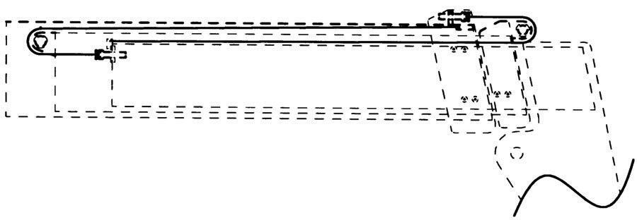
Basic Machine Grease Fitting Locations
Every 50 Hours (or weekly)
Refer to the illustrations on the facing page for locations.
--- BOOM AREA ---
1. Boom-to-frame upright pivot pins (2)
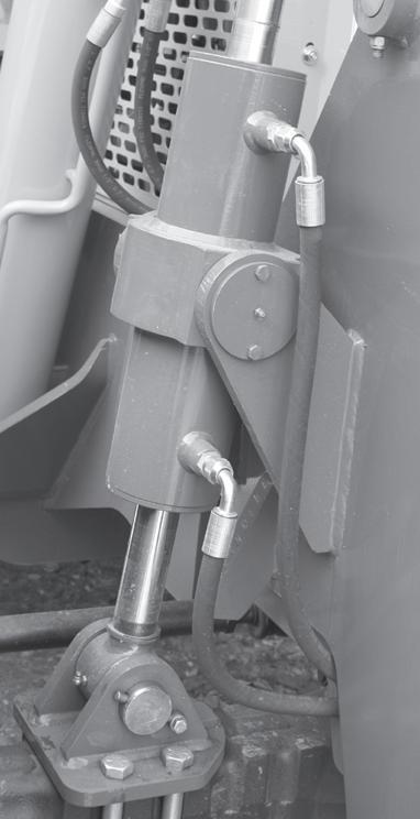
2. Rod end slave cylinder pivot pins (2)
3. Rod end lift cylinder pins (2)
4. Extend cylinder pin
5. Chain sheaves pins, (2)
6. Dynattach-to-boom nose pivot pin
7. Tilt cylinder pivot pins (2)
8. Boom slide pads - as required, front and rear
General Information
Chapter 8
Service And Storage Warning
When a problem occurs, do not overlook simple causes such as an empty fuel tank. Check for leaks and broken connections. Make note of any specific symptoms, noises, etc. and contact your local Manitou Group dealer.
BEFORE performimg any service on the Telescopic Handler, unless expressly instructed to the contrary, exercise the MANDATORY SAFETY SHUTDOWN PROCEDURE (p. 17, Safety chapter). After service has been performed, BE SURE to restore all guards, shields and covers to their original positions BEFORE resuming machine operation.
NOTE: All service routines, with the exception of those described under the “Dealer Services” topic, are owner-operator responsibilities. All operator services described under the subtopics are also referred to on a decal located on the inside right side panel of the operator’s station. Refer to the Lubrication chapter of this manual for lubrication information.
NOTE: This Service and Storage chapter describes procedures to follow for making routine maintenance checks, adjustments and replacements. Most of the procedures are also referred to in the Maintenance chapter of this manual. For engine related adjustments and servicing procedures, refer to the engine manual provided.
Precautions
DO NOT perform any maintenance or repair without the owner’s prior authorization. Allow only trained personnel to service the machine.
Warranty repairs can only be done by an authorized Manitou Group dealer. Dealers know what portions of the machine are covered under the terms of the Manitou Group Warranty and what portions are covered by other vendor warranties.
IMPORTANT: Always dispose of waste lubricating oils, anti-freeze and hydraulic fluids according to local regulations or take them to a recycling center for disposal. DO NOT pour them onto the ground or into a drain.
Dealer Services
The following areas of internal components service replacement and operating adjustments should only be performed by (or under the direction of) an authorized Manitou Group Telescopic Handler dealer.
IMPORTANT: DO NOT service or repair major components, unless authorized to do so by your Manitou Group dealer. Any unauthorized repair will void the warranty.
Power Train Components
The engine and transmission are coupled directly to each other. All service routines related to the internal components are precise and critical to proper power train operation. The axle differential and planetary ends are also sophisticated assemblies that require special know-how and tools for servicing.
IMPORTANT: If any powertrain components are suspected of faulty operation, contact your Manitou Group dealer for assistance.
Hydraulic System Components
Valves, pumps, motors and cylinders are sophisticated assemblies which require special know-how and tools for servicing. All cylinders are appropriately designed with particular strokes, diameters, checks and hose connection provisions unique to the machine application requirements. A hydraulic schematic (Maintenance chapter) can be used as a guide for service reference, as required.
Warning
Tilt, lift, extend and leveling cylinders have counterbalance valves. These valves keep hydraulic fluid from entering and exiting the cylinders while they are not being activated, and they are under extremely high pressure. Before removing one of these valves, you ARE REQUIRED to call your Manitou Group dealer or Manitou Group Service Department. Failure to do so may result in serious injury or death.
Internal service on any of these components should only be performed by (or under the direction of) an authorized Manitou Group Telescopic Handler dealer.
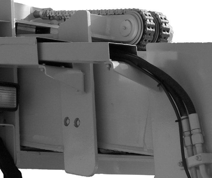
Electrical Components
An electrical system schematic is provided, which includes instrumentation, electrical components and switch connections. It is located at the back of this manual and can be used as a guide for service reference, as required.
Operator Services
Some of the operator-related services will require access to components located inside the superstructure, under shields, hoods and covers. The chart on this page notes the components accessed in each particular area.
Access To Components Chart
Warning
DO NOT smoke or allow any open flames in the area while checking or servicing hydraulic, battery or fuel systems; all contain highly flammable liquids or explosive gases, which can cause an explosion or fire if ignited. Wear a face shield when disassembling spring-loaded components or working with battery acid. Wear a helmet or goggles with special lenses when welding or cutting with a torch.
When working beneath a raised machine, always use blocks, jack-stands or other rigid and stable supports. Wear appropriate protective clothing, gloves, and shoes. Keep feet, clothing, hands and hair away from moving parts.
Always wear safety glasses or goggles for eye protection from electric arcs from shorts, fluids under pressure, and flying debris or loose material when the engine is running or tools are used for grinding or pounding.
NEVER weld on bucket, forks, boom, support frame or ROPS/FOPS without the consent of the manufacturer. These components may be made with metals that require special welding techniques, or with designs that do not allow weld repairs. NEVER cut or weld on fuel lines or tanks.
If repair welding is ever required, BE SURE to attach the ground (-) cable from the welder as close as possible to the area to be repaired. Disconnect the positive (+) and negative (-) cables from the battery. Disconnect the connectors to the Electronic Control Module (ECM).
Choose a clean, level work area. Make sure you have sufficient room, clearances, and adequate ventilation. Clean the walking and working surfaces. Remove oil, grease and water to eliminate slippery areas. Utilize sand or oil absorbing compound, as necessary, while servicing the Telescopic Handler.
Before starting inspection and repair, move the machine onto a level surface, shut down engine, and release all hydraulic pressure. Always lower the boom to full ground contact. Place all controls in neutral.
Block the wheels. Remove the ignition key. Remove only guards or covers necessary to provide needed access. Wipe away excess grease and oil.
Excessively worn or damaged parts can fail and cause injury or death. Replace any cracked or damaged parts. Use only genuine Manitou Group parts for service.
Use care not to damage machined and polished surfaces. Clean or replace all damaged or painted-over plates and decals that cannot be read.
Warning
NEVER leave guards off or access doors open when the machine is unattended. Keep bystanders away if access doors are open.
After servicing, check the work performed, that no parts are left over, etc. Install all guards and covers.
CHECK FUEL and DIESEL EXHAUST
Warning
Static electricity can produce dangerous sparks at the fuel-filling nozzle. Do not wear polyester, or polyester-blend clothing while fueling. Before fueling, touch the metal surface of the machine away from the fuel fill to dissipate any built-up static electricity. Do not re-enter the machine but stay near the fuel filling point during refueling to minimize the build-up of static electricity. Do not use cell phones while fueling. Make sure the static line is connected from the machine to the fuel truck before fueling begins.
Ultra-Low Sulfur Diesel (ULSD) poses a greater static ignition hazard than earlier diesel formulations. Avoid death or serious injury from fire or explosion; consult with your fuel or fuel system supplier to ensure the entire fuel delivery system is in compliance with fueling standards for proper grounding and bonding practices.
NOTE: Only machines equipped with the 90 Kw (120 hp) engine will use diesel exhaust fluid.
The fuel and diesel exhaust fluid level is shown on there repective level gauge on the instrument panel. After operation each day, the fuel tank should be filled to prevent water from condensing in the tank. Diesel exhaust fluid should be added if it is low. Engine power will be reduced if the level is allowed to drop to low. See the Lubrication chapter for the diesel fuel and diesel exhaust fluid requirements.
7. Prime the fuel system: a. Turn the ignition key to the “ON” position without starting the engine. b. Wait for the fuel supply pump to stop running (about 20 to 30 seconds). c. Turn the ignition key to the "OFF" position. d. Repeat steps 7a through 7c four times.
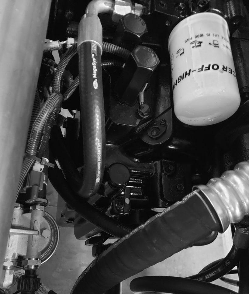
Check Fuel Water Separator
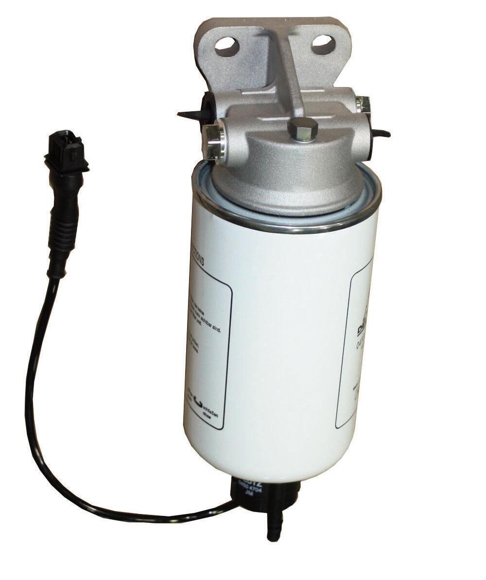
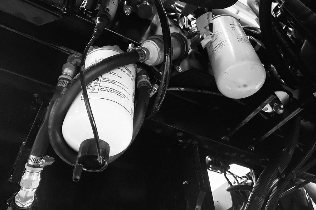
NOTE: The primary fuel filter/water separator (A) and secondary fuel filter (B) will require occasional replacement to maintain a clean and adequate fuel flow for maximum engine horsepower. The frequency of filter replacement will be determined by the cleanliness of available fuel, the care used in storing fuel supplies, and the operating conditions in which the machine is used.
Check the primary fuel filter/water separator (A) for water and debris.
IMPORTANT: Drain water into a suitable container and dispose of properly.
1. Disconnect the water level sensor electrical connector (A).
2. Loosen vent screw (C) on the top of the filter head several turns.
3. Loosen drain plug (B) until fluid runs out. Let drain until pure diesel fuel flows from the drain.
4. When fuel starts to drain out, tighten drain plug securely.
5. Re-connect the water level sensor electrical connector.
6. Tighten vent screw (C).
A drain plug is also provided in the bottom of the fuel tank for removing condensation and other foreign materials. Open the plug and allow water and fuel to drain into a container until only clear fuel is flowing from the tank.
Check Engine Oil Level
With the machine on level ground, and the engine stopped for 15 minutes or more, open the access door on the right side of the engine cover and remove the engine oil dipstick (A). Wipe it clean, re-insert it and remove to obtain a reading. If the oil level is below the crosshatch pattern on the dipstick, fill with the required amount of oil through the oil filler (B) to bring the level to within the crosshatch pattern. Oil levels anywhere within the crosshatch are considered full. See the Lubrication chapter for the type of oil to use.
Check Radiator Coolant Level
With the machine on level ground, visually check the level of the engine coolant through the sight gauge located on the back of the radiator as shown. Coolant level should be at the center of the sight gauge.
Check Transmission Oil Level
The machine must be on level ground. With the engine and transmission at operating temperature, parking brake on, transmission in neutral and engine speed at low idle, remove the access cover to the transmission and hydraulic pump. Remove the dipstick (A) and check the oil level. Add the required amount of oil to bring the level to the FULL mark. See the Lubrication chapter for the type of oil to use.
If the coolant level is low, remove the radiator cap and slowly add a low-silicate ethylene glycol based coolant mixed with quality water and supplemental coolant additives (SCAs) suitable for heavy-duty diesel engines until the coolant is at the center of the sight glass. See your engine manual for additional information. Replace the radiator cap securely.
Warning
DO NOT remove the radiator cap when the engine is running hot or overheated. Coolant is extremely hot and under pressure and it can burn your skin. Allow sufficient time for the radiator to cool BEFORE relieving the pressure and removing the cap.
NOTE: Do not fill the radiator to the top of the radiator tank.
NOTE: If the engine is operated with a loose radiator cap, the pressure bypass will not work and the engine will run hot.
Check Hydraulic Oil Level
The machine must be on level ground with boom lowered and completely retracted. The fluid MUST be cool when checking the reservoir level, to reduce the possibility of overfilling the hydraulic system.
Visually check the level of the hydraulic oil through the sight gauge (A) located on the right side of the front hood. If low, remove the access cover from the front hood to replenish the oil through the filler cap (B). See the Lubrication chapter for the type of oil to use.
IMPORTANT: Be careful when removing the reservoir filler cap so that no dirt or other foreign matter enters the hydraulic system. DO NOT OVERFILL.
Check Foam Filled Or Solid Rubber Tires
Check these tires for deep cuts, abrasions or gouges in the wear surface and sidewalls that may affect the tires performance.
NOTE: The RS9-50 model telehandler requires the use of foam filled or solid rubber tires.
Check Tire Pressures
To ensure proper operating stability and extend tire life, proper and equal tire pressure should be maintained in all four tires.
Check tire pressures “cold.” Inflate as necessary per the chart below:
13.00 x 24 - 12 PR: 450 kPa (65 psi)
14.00 x 24 - 12 PR: 430 kPa (62 psi)
14.00 x 24 - 16 PR: 480 kPa (70 psi)
NOTE: If the tires have been filled with water or calcium chloride for ballast, a calcium chloride tire pressure gauge MUST be used to check the tire pressure.
Warning
Inflating or servicing tires can be dangerous. Whenever possible, trained personnel should service and mount tires. To avoid possible death or serious injury, follow the safety precautions listed:
1. BE SURE the rim is clean and free of rust.
2. Lubricate both the tire beads and rim flanges with a soap solution. DO NOT use oil or grease.
3. DO NOT place fingers on the tire bead or rim during inflation. Use a clip-on tire chuck with a remote hose and gauge, which allows standing clear of the tire while inflating it.
4. NEVER inflate beyond 240 kPa (35 psi) to seat the beads. If the beads have NOT seated by the time the pressure reaches 240 kPa (35 psi), deflate the assembly, reposition the tire on the rim, relubricate both parts and re-inflate. Inflation pressure beyond 240 kPa (35 psi) with unseated beads may break the bead or rim with explosive force sufficient to cause death or serious injury.
5. After seating the beads, adjust the inflation pressure to the recommended operating pressure listed.
6. DO NOT weld, braze, or otherwise attempt to repair and use a damaged rim.
To ensure proper load carrying capability, original equipment tires comply with the specifications published in the Tire and Rim Association Yearbook Replacement tires MUST meet the same specifications. When replacing tires, be sure all tires are of the same type, quality and load rating, and the same size as the original equipment. When removing tires, follow industry safety practices. Deflate completely prior to removal. After assembly of the tire on the rim, use a safety cage or restraining device while inflating.
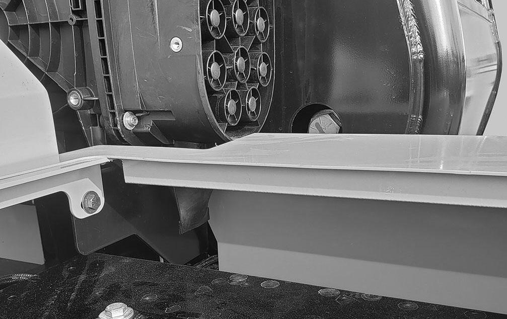
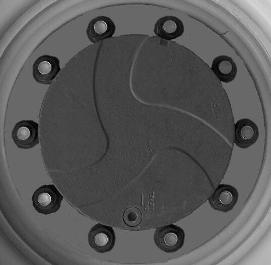
Check Wheel Nut Torque
On new machines, or any time a wheel has been removed, re-torque until 610 Nm (450 ft.-lbs.) is maintained.
Check Instruments Operation
Allow the engine to warm up for 1-2 minutes or 2-4 minutes in below freezing temperatures before beginning operation. Indicator lamps should be OFF and gauges should register normal readings. Tilt the frame from side to side with the frame leveling control and note the angle indicator movement.
Check General Machine Operation And Condition
Are any decals missing or damaged? Are all guards, shields and covers in place? Do all controls function smoothly and properly? Are there any abnormal vibrations or noises? Are any hose or fitting connections leaking? Is the engine exhaust color normal?
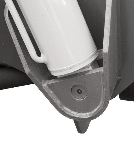
Check Dust Ejection Valve
Inspect the dust ejector (A) for cuts and tears. Replace the valve if damage is found.
The dust ejector is a thin flexible rubber boot located at the bottom of the pre-cleaner on the air cleaner assembly. It is used to accumulate and remove dust ejected from the pre-cleaner.
6. PWP System switch “OFF,”
7. Remote switch plugged in and “ENGAGED.”
Activation Tests
To test the PWP System activation logic:
1. Start the engine and press the PWP rocker switch to “ON.” l The PWP System lamp in the switch should be flashing. l The PWP switch lamp should be illuminated continuously after three seconds, indicating that the PWP System has been activated. l The parking brake should engage, as indicated by the lamp in the parking brake switch illuminating.
2. Apply the service brakes.
Purge the dust ejection valve of dust by squeezing the valve until it opens. This may have to be performed multiple time depending on severity of dust or debris in the valve. If dust will not purge from the valve by squeezing the valve, remove the valve and clean it out by hand.
CHECK PERSONNEL WORK PLATFORM (PWP) SYSTEM (if used)
Warning
If the PWP System fails to operate properly during any of the PWP System checks, DO NOT USE the machine until the cause has been corrected. Contact your dealer (or Manitou Group) for service information and parts.
Machine Position
The following must be performed before begining the PWP System checking procedures:
1. Machine on level surface,
2. Boom fully lowered,
3. Frame level,
4. Transmission in “N” (Neutral),
5. Parking brake switch “OFF,” l The carriage tilt and auxiliary functions should now be disabled. The joystick control should continue to function normally for boom raise/lower and extend/retract.
Lockout Tests
To test the transmission and joystick control lockout logic: l The transmission should remain de-clutched, allowing the engine to increase speed easily. l Return the transmission selector to “N” (Neutral) after the check.
1. Shift transmission into “F” (Forward) and increase the engine speed slightly.
2. Have an assistant move the remote shutdown switch to “Dis-engaged.” l The joystick control should now be disabled, so that boom raise/lower and extend/retract will no longer function. l Have the assistant move the remote shutdown switch to “Engaged” after the check. l The joystick control should now be disabled so that boom raise/lower and extend/retract no longer function. l Repeat the procedure with the frame tilted to the left. l Return the frame to a level position after the checks.
3. Tilt the frame to the right slightly more than two degrees.
De-activation Tests
To test the PWP System de-activation logic:
1. Turn the key switch to “OFF” and wait for the engine to stop. Then turn the key switch back to “ON.” l The PWP switch lamp and the parking brake switch lamp should both be illuminated.
2. Turn the key switch to “OFF” and then turn the PWP rocker switch to “OFF.” Turn the key switch back to “ON.” l The PWP switch lamp should be flashing and the parking brake switch lamp should be on continuously. l The PWP switch lamp and the parking brake switch lamp should go off after approximately three seconds of brake pedal application.
3. Start the engine and apply the service brakes.
If PWP System fails to perform properly, troubleshoot using the chart on page 95. Contact your dealer for service information and parts.
NOTE: Perform all other service requirements up to this point, as well as the following:
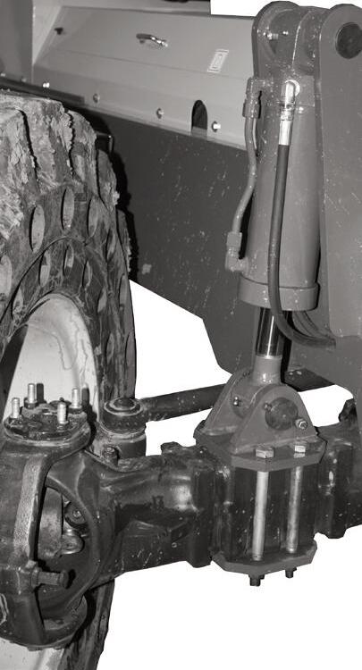
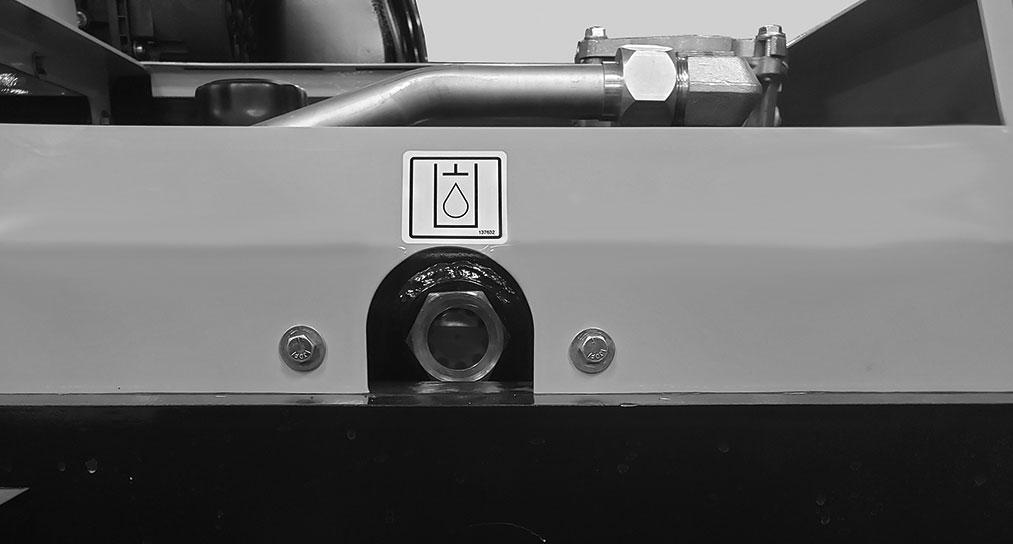
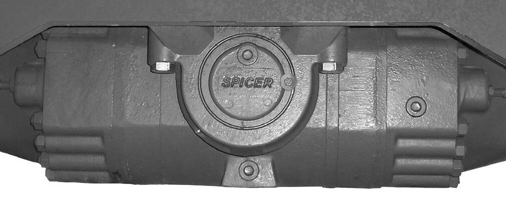
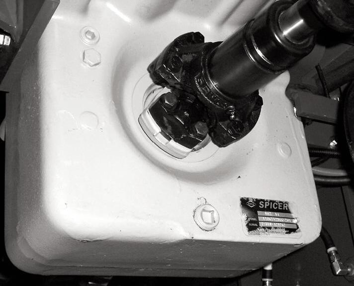
Check Axle Oil Levels
Differential
NOTE: The Telescopic Handler should be on a level surface for this procedure.
Remove the oil check plug. See illustration below. Oil should flow from the hole. If low, remove the oil fill plug and add oil until it flows from the check hole. Replace the plug, wait 10 to 15 minutes and repeat the fill procedure. Continue this process until the differential is full. See the Lubrication chapter for the proper oil specification. Replace the check and fill plugs.
Lubricate Grease Points
Refer to the Lubrication chapter of this manual for grease fitting locations and other related details.
The following initial oil and filter changes should be made at 100 hours on a new machine. Thereafter these changes should be made at the regular maintenance schedule listed below. Refer to those schedules for the necessary procedures.
Engine Oil and Filter (250 Hours)
Transmission Oil and Filter(1000 Hours)
Hydraulic Return Filter Element(1000 Hours)
Torque the boom chains after the first 100 hours of operation on new machines or anytime a chain has been replaced. Thereafter the boom chains should be inspected for wear and proper tension at the regular service interval of 250 hours. Refer to the boom chain torqueing procedure in the 250 hour service interval.
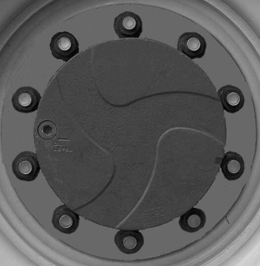
Planetary Hubs
NOTE: The planetary hubs can be checked without jacking up the machine.
The planetary hubs have one plug each used for filling and draining. See illustration below. For checking the level and filling, position the wheel until the oil level arrow is horizontal. Remove the plug. If oil does not run out, add oil until it overflows. Check the remaining hubs the same way. Refer to the oil specifications found in the Lubrication chapter of this manual.
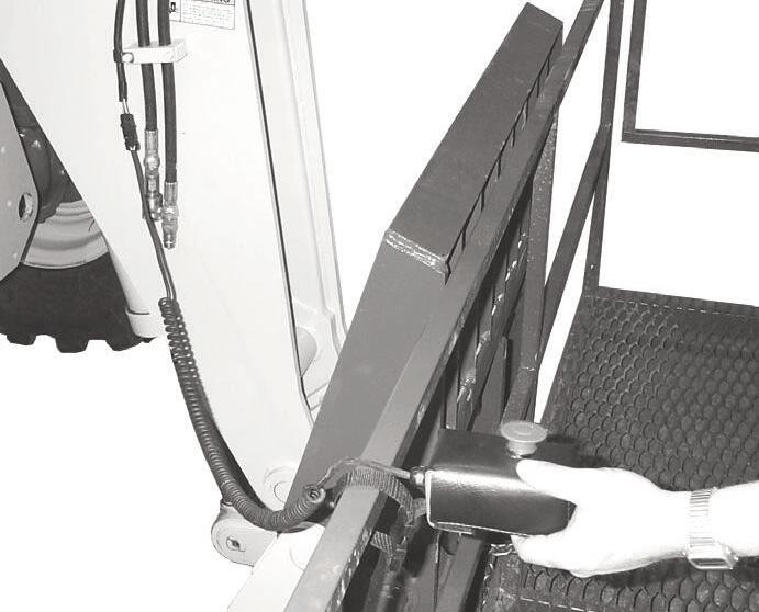
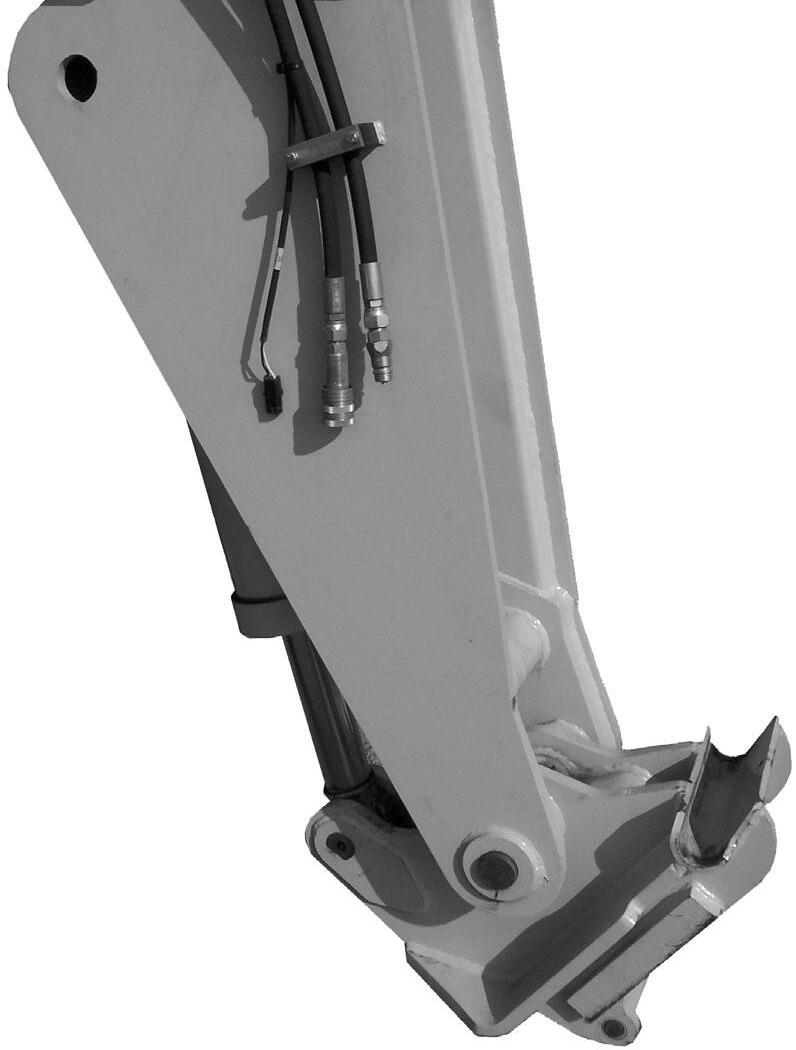
Check And Torque Boom Leaf Chains
Inspect the leaf chains for proper tension. On the threesection boom, two of the chains are on the top front of the boom. A third chain is accessible from inside the rear of the boom (see three-section boom illustration).
Torque the two chains on the front of the three-section boom to 40 Nm (30 ft.-lbs.). Lubricate with 80W-90 oil.
IMPORTANT: On the four-section boom, on new machines or when chains have been replaced, it is necessary to retorque the front-center single chain and the front-outer double chains after one hundred (100) hours of operation. Failure to do so may allow the chains to become slack, which can result in a chain jumping off a sheave. If this occurs, it could result in severe damage to the boom assembly.
The retract chains on the 2nd intermediate boom and the inner boom are pre-set at the factory and do not require adjustment, unless they are replaced.
Inspect the leaf chains for wear. Run the boom out slowly to inspect. Conditions to look for include: cracked or broken plates, protruding or turned pins, and excessive wear. With a steel tape, measure 16 links of the strand that flexes over the sheaves. If the section measures 314 mm (12.375”) or more, the chain should be replaced. DO NOT repair sections of a chain. Replace the complete chain.
Chain anchors and sheaves also require inspection, for worn or broken fingers and worn flanges.
IMPORTANT: On the three-section boom, on new machines or when chains have been replaced, it is necessary to retorque the front double chain assembly after one hundred (100) hours of operation. Failure to do so may allow the chains to become slack, which can result in a chain jumping off a sheave. If this occurs, it could result in severe damage to the boom assembly.
On the four-section boom, three chains are on the top front of the boom. A fourth and fifth chains are accessible from the rear of the boom (see four-section boom illustration).

After any chain has been replaced, operate under loaded conditions and re-check the torque. Adjust the chains per the following procedure: Extend the boom to its maximum length, then retract the boom slowly until the chain slack allows the chain to rest on the top of the boom. Torque the two chains on the front of the three-section boom to 40 Nm (30 ft.-lbs.) and the three chains on the front of the four-section boom to 68 Nm (50 ft.-lbs.). Lubricate with 80W-90 oil.
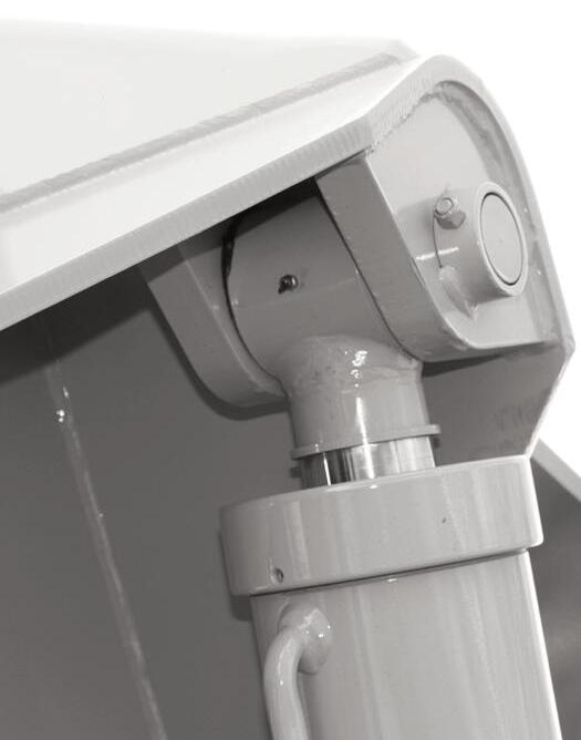
Check Boom Slide Pad Wear And Clearance
The boom is equipped with special nylon low-friction slide pads between the telescopic sections (see “Typical Slide Pad Detail” illustration). These are pregreased and initially worn in at the factory. Normally greasing is not required, except for maintaining a light film of grease on the pad tracking areas of the boom sections. An exception would be if a boom section has been replaced.
Visually check for loose pad bolts. The bolts are torqued to 40 Nm (30 ft.-lbs.). If the bolts are retorqued at any time, LoctiteÒ 271 (red) thread lock or equivalent must be re-applied to the bolts.
Torque the three chains on the front of the four-section boom to 68 Nm (50 ft.-lbs.). Lubricate with 80W-90 oil.
If the boom starts to chatter under load, grease the slide pads and wipe off the excess grease. Maintain a clearance of 1/16” between the top or side slide pads and the boom. Shims can be added to achieve the proper clearance. Loosen the bolts and insert shims until proper clearance is obtained.
NOTE: When inserting shims in the side slide pads, be sure to place equal shims on both sides of the boom for even distribution of clearance.
Re-apply LoctiteÒ 271 (red) thread lock or equivalent to the bolts and re-torque to 40 Nm (30 ft.-lbs.). Bottom slide pads should not be shimmed and should be replaced when the thickness is worn down to 9.5 mm (3/8”).
Warning
Failure to maintain proper slide pad clearance and thickness could cause damage to the boom, resulting in sudden boom failure.
CHECK CHARGE-AIR-COOLER AND PIPING
Inspect the charge-air-cooler for dirt and debris blocking the fins. Check for cracks, holes or other damage. Inspect the charge-air-piping and hoses for leaks, holes, cracks, or loose connections. Verify the chargeair-piping hose clamps are torqued to 5.1 Nm (45 inlbs).
Replace any damaged or worn parts.
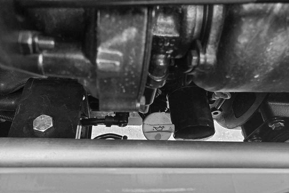
Change Engine Oil And Filter
NOTE: Follow specifications in the Lubrication chapter for type and viscosity of new oil to use for the change interval.
Change the engine oil and filter using the following procedure:
1. With the engine warm, remove the crankcase drain plug located on the left side of the engine oil pan.
IMPORTANT: DO NOT discharge oil onto ground. Catch and dispose of per local waste disposal regulations.
2. The engine oil filter (A) should be changed at every oil change interval. Using a suitable filter wrench, remove and discard the filter.
IMPORTANT: Filtration of oils is critical to proper lubrication. Always change filter with every oil change. Use only genuine OEM engine replacement filters.
3. Apply a thin coat of clean engine oil to the sealing gasket of the new oil filter.
4. Wipe the filter sealing surface on the engine with a clean cloth.
5. Turn new oil filter on by hand until filter contacts the sealing surface then turn the filter an additional 3/4 turn.
6. Clean and re-install the drain plug.
7. Remove the oil fill cap (B) and re-fill the crankcase with new oil.
NOTE: The oil capacity listed is approximate. Always verify oil level with the engine oil dipstick.
8. After new oil has been added, run the engine at idle speed until the oil pressure lamp is off. Check for leaks at the filter and drain plug.
9. Verify the oil level is at the “Full” mark on the engine oil dipstick (C).
IMPORTANT: Low engine oil level and over full engine oil levels can cause engine damage.
Service Every 500 Hours or 6 Months
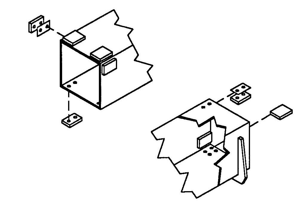
Check The Batteries And Cables
The batteries furnished in the machine are 12-volt, wet-cell batteries.
Warning
Explosive gas is produced while a battery is in use or being charged. Keep flames or sparks away from the battery area. Make sure battery is charged in a well-ventilated area.
NEVER lay a metal object on top of a battery as a short circuit can result.
Battery acid is harmful on contact with skin or fabrics. If acid spills, follow these first aid tips:
1.IMMEDIATELY remove any clothing on which acid spilled.
2.If acid contacted the skin, rinse the affected area with running water for 10 to 15 minutes.
3.If acid came in contact with the eyes, flood the eyes with running water for 10 to 15 minutes. See a doctor at once. NEVER use any medication or eye drops unless prescribed by the doctor.
4.To neutralize acid spilled on the floor, use one of the following mixtures: a.0.5 kg (1 pound) of baking soda in 4 liters (4 quarts) of water. b.0.4 liters (1 pint) of household ammonia in 4 liters (4 quarts) of water.
Whenever battery is removed from the unit, BE SURE to disconnect the negative (-) battery terminal connection first.
The top of the battery must always be kept clean. Clean the battery with a brush dipped in an alkaline solution (ammonia or baking soda and water). After the foaming has stopped, flush the top of the battery with clean water.
Use an inductive charging and cranking system analyzer to load-test the state of charge of the battery. If the charge is low, use a battery charger to charge the battery. Replace the battery if it will not except a charge or will not maintain a charge.
If conventional batteries are used, remove the cell caps or covers and check the electrolyte level in each cell. Fill each battery cell with water.
Use a hydrometer to measure the specific gravity of each cell. If the specific gravity of any cell is below 1.200, the battery must be replaced.
If the terminals and cable connection clamps are corroded or have a buildup, disconnect the cables and clean the terminals and clamps with a battery brush or wire brush untill the terminal and connections are shiny.
Connect the cables and tighten the battery connections. Coat the terminals with grease to prvent corrosion. Wash hands after handling the battery.
Jump Starting
If the battery becomes discharged or does not have enough power to start the engine, use jumper cables and the following procedure to jump-start the engine.
Warning
The ONLY safe method for jump-starting a discharged battery is for TWO PEOPLE to perform the following procedure. The second person is needed for removing the jumper cables so that the operator does not have to leave the operator’s compartment while the engine is running. NEVER connect the jumper cables directly to the starter solenoid of either engine. DO NOT start the engine from any position other than the operator’s seat, and then ONLY after making sure all controls are in “neutral.”
Closely follow the jump-start procedures, in the order listed, to avoid personal injury. In addition, wear safety glasses to protect your eyes, and avoid leaning over the batteries while jump-starting.
DO NOT attempt to jump-start the machine if the battery is frozen, because this may cause it to rupture or explode.
IMPORTANT: BE SURE that the jumper battery is also a 12-volt D. C. battery, and the vehicle used for jump starting has a negative-ground electrical system.
1. Turn the key switches on both vehicles to “OFF.” Be sure that both vehicles are in “Neutral” and NOT touching.
2. Connect one end of the (red) positive (+) jumper cable to the positive (+) battery terminal on the disabled machine first. DO NOT allow the positive (+) jumper cable clamps to touch any metal other than the positive (+) battery terminals. Connect the other end of the positive jumper cable to the jumper battery positive (+) terminal.
3. Connect one end of the (black) negative (-) jumper cable to the jumper battery negative (-) terminal.
4. Make the final negative (-) jumper cable connection to the disabled machine’s engine block or frame (ground) NOT to the disabled machines negative battery post. If making the connection to the engine, keep the jumper cable clamp away from the battery, fuel lines, and moving parts.
NOTE: Twist the jumper cable clamps on the battery terminals to ensure a good electrical connection.
5. Start the engine. If it does not start immediately, start the jumper vehicles engine to avoid excessive drain on the booster battery.
6. After the machine has started and is running smoothly, have the second person remove the jumper cables (negative (-) jumper cable first) from the jumper vehicle battery, and then from the disabled machine, while ensuring NOT to short the two cables together.
Allow sufficient time for the alternator to build up a charge in the battery before operating the machine or shutting off the engine.
NOTE: If the battery frequently becomes discharged, have the battery checked for possible dead cell(s), or troubleshoot the electrical system for possible short circuits or damaged wire insulation.
Check Fan Belt Tensioner
With the engine stopped, check the tensioner arm, pulley and stops for cracks. If any cracks are noticed, the tensioner must be replaced.
With the belt installed, verify that neither tensioner arm stop is in contact with the spring casing stop. If either of the stops is touching: Verify that the correct belt is installed. If the correct belt is installed, replace the belt. After replacing the belt, if the tensioner arm stops are still in contact with the casing stop, replace the tensioner.
With the belt installed, check the location of the belt on the belt tensioner pulley. The belt should be centered on, or close to the middle of the pulley. Misaligned belts, either to far forward or backward, can cause belt wear, belt roll-off malfunctions, or increase uneven tensioner bushing wear. If belt is not centered on the tensioner pulley, the tensioner will likely need to be replaced.
Refer to the Deutz engine Operation Manual for additional information.
Check Coolant System Antifreeze
Check the antifreeze concentration. Use a mixture of 50 percent water and 50 percent ethylene glycol or propylene glycol-base antifreeze to protect the engine to -32° C (-25° F) year round.
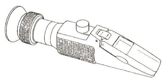
An antifreeze refractometer provides a reliable, easy to read, and accurate measurement of freezing point protection and antifreeze concentration.
To check the antifreeze concentration:
1. Place a drop of coolant on the refractometer window and shut the lid.
2. Look through the eyepiece and focus.
3. Record the freeze point protection for either ethylene glycol or propylene glycol coolants.
NOTE: Factory filled with an ethylene glycol based antifreeze.
Antifreeze is essential in every climate.
It broadens the operating temperature by lowering the coolant freezing point and raising its boiling point.
The corrosion inhibitors also protect the cooling system components from corrosion and provide longer componet life.
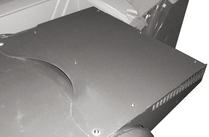
Clean Air Conditioning Condenser
NOTE: Clean the condenser more often if there is a noticeable decrease in A/C performance.
IMPORTANT: Do not use a water jet or high-pressure steam, because this could damage the fins.
1. Remove the six screws (1) from the top cover of the condenser.
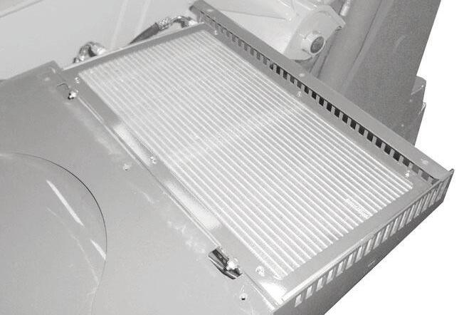
2. Remove the cover to gain access to the condenser (2).
4. Clean the condenser use a jet of compressed air aimed in the same direction as the air flow.
NOTE: To aid in the cleaning process, carry out this operation with the condenser fans running.
5. Re-install the top cover.
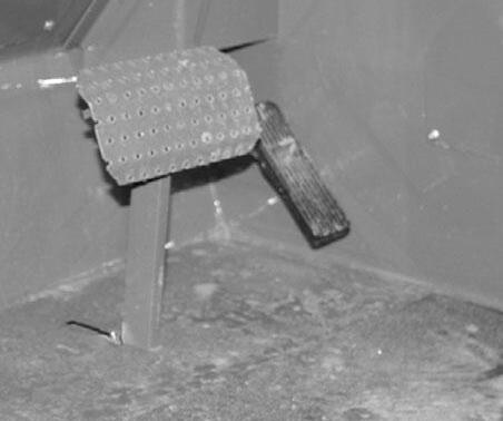
CLEAN/CHANGE CAB VENTILATION FILTER
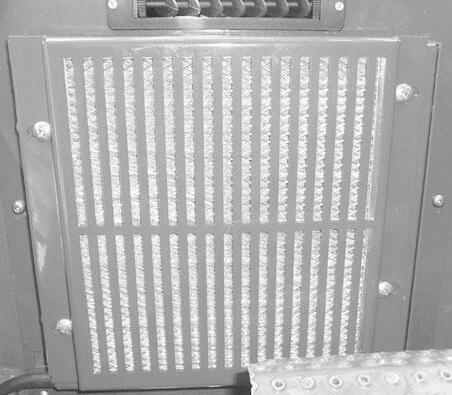
NOTE: Clean or change the filter more often if there is a noticeable decrease in air flow from the air vents.
1. Remove the four screws (1) from the filter protective cover located on the lower portion of the dash in front of the brake pedal.
3. Clean any large debris that may have collect on the top side of the condenser.
2. Remove the filter from the cover.
3. Clean the filter with a jet of compressed air.
4. Check the condition of the filter and replace it if neccessary.
5. Install the filter in the protective cover, then reinstall the protective cover.
NOTE: Perform all other service requirements up to this point, as well as the following:
Change Fuel Filter
This telehandler is equipped with a primary fuel filter/water separator (A) and a secondary fuel filter (B).
The frequency of filter replacement will be determined by the cleanliness of available fuel, the care used in storing fuel supplies and the operating conditions in which the machine is used.
Warning
NEVER service the fuel system while smoking, while near an open flame, or after the engine has been operated and is hot.
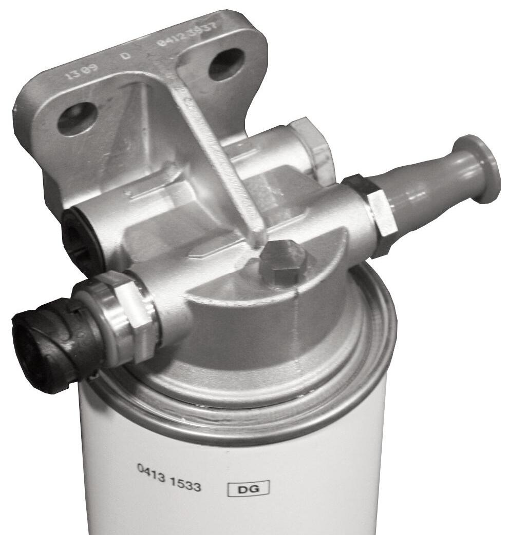
Primary Fuel Filter/Water Separator Replacement
1. Thoroughly clean fuel filter assembly and surrounding area.
2. Loosen vent screw (D) on the top of the filter head several turns.
3. Disconnect water sensor wiring (B) from the (A) filter.
4. Loosen drain plug (C) and drain fuel into a suitable container.
5. When fuel has drained, turn the drain plug out completely.
6. Using a filter wrench, remove the filter (A) from the filter head.
Primary Fuel Filter/Water Separator
7. Inspect filter head for cleanliness. Clean as required.
8. Apply a small amount of fuel to the sealing gasket of the replacement filter.
9. Turn replacement filter onto filter head until the filter contacts the filter head, then turn an additional 3/4 turn.
10. Turn drain plug into filter and re-connect the water sensor wire.
11. Tighten the vent screw (D).
12. Prime the fuel system: a. Turn the ignition key to the “ON” position without starting the engine. b. Wait for the fuel supply pump to stop running (about 20 to 30 seconds). c. Then turn ignition key to the “OFF” position. c. Repeat steps 12a through 12c four times.
Secondary Fuel Filter Replacement
1. Thoroughly clean fuel filter assembly and surrounding area.
2. Using a filter wrench, remove the filter from the filter head.
3. Inspect filter head for cleanliness. Clean as required.
Secondary Fuel Filter
4. Apply a small amount of fuel to the sealing gasket of the replacement filter.
5. Turn replacement filter onto filter head until the filter contacts the filter head, then turn an additional 3/4 turn.
6. Prime the fuel system: a. Turn the ignition key to the “ON” position without starting the engine. b. Wait for the fuel supply pump to stop running (about 20 to 30 seconds). c. Then turn ignition key to the “OFF” position. d. Repeat steps 6a through 6c four times.
Warning
Escaping diesel fuel under pressure can have sufficient force to penetrate the skin. Before applying pressure to the fuel system, BE SURE all connections are tight and lines and hoses are not damaged. Use a piece of wood or cardboard to search for suspected leaks. If injured by escaping fuel, see a doctor familiar with this type of injury at once or gangrene may result.
After fuel filter replacement, start the engine and operate approximately 5 minutes at low idle. Check for fuel leaks.
Diesel Fuel System
Whenever faulty or plugged injectors or injection pump service is indicated by abnormal engine operation, see your authorized engine dealer.
NOTE: Only an authorized engine dealer can perform warranty service on the engine.
Change Transmission Oil And Filter
Operate the machine long enough to warm the transmission oil to 65°C-93°C (150°F-200°F). Shut off the engine. Access to filter is from under the access cover on the front hood section. Access to the drain plug is from underneath the machine. Proceed as follows:
1. Remove the drain plug and drain old oil. Replace the drain plug.
IMPORTANT: DO NOT discharge oil onto ground. Catch and dispose of per local waste disposal regulations.
2. Remove and discard the oil filter (A). Wipe the sealing surface on the transmission with a clean cloth. Apply a thin coat of clean oil to the new oil filter gasket. Hand tighten.
3. Refill the transmission with new oil as listed in the Lubrication chapter of this manual.

IMPORTANT: DO NOT OVERFILL! lf the oil level is too high, oil foaming, excessively high oil temperature and oil leakage at the seals could result.
4. Start and run the machine long enough for the oil to circulate and warm slightly. Recheck the level with the dipstick (B).
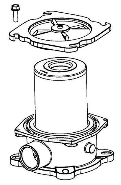
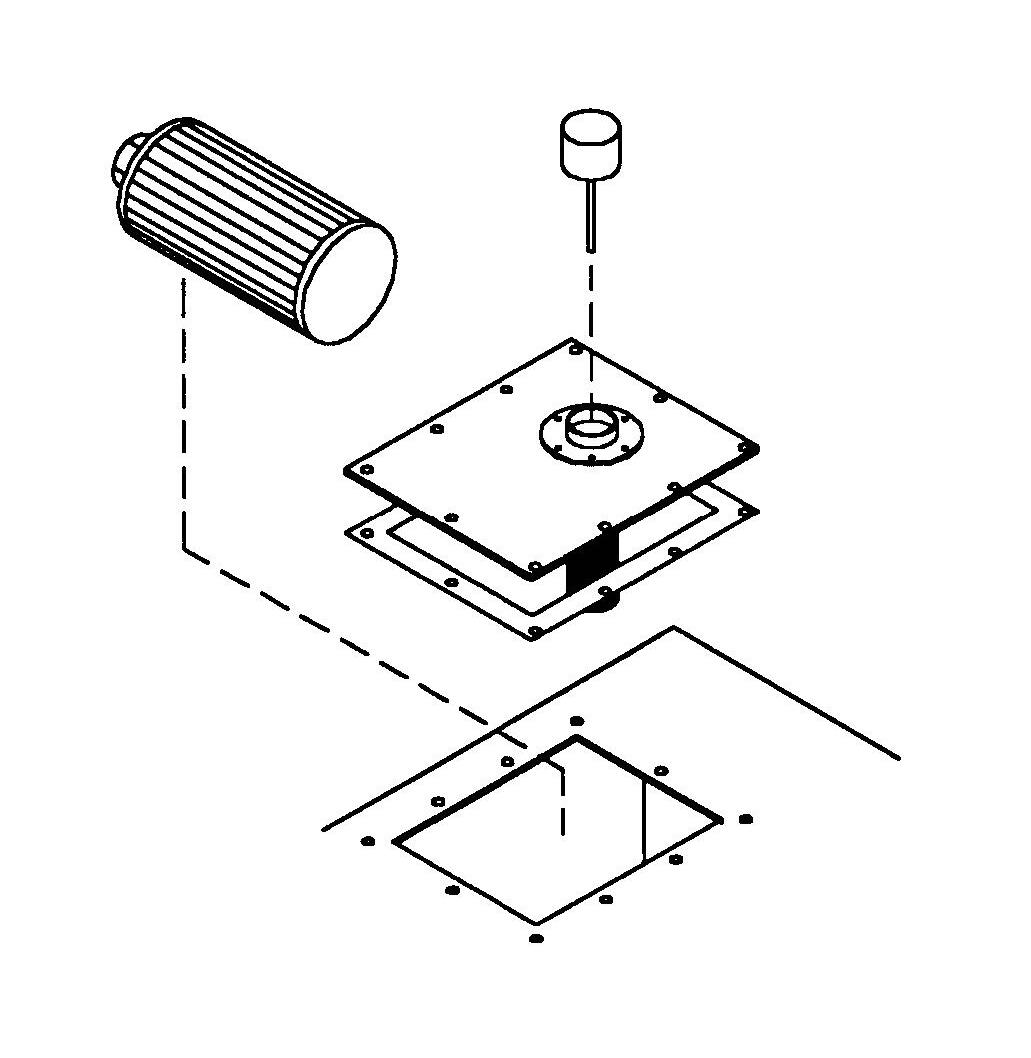
Change Hydraulic Return Filter Element
Warning
When servicing the hydraulic system, lower the boom to the ground.
This element is a cartridge-type accessible from a housing on top of the hydraulic reservoir. Initial replacement is after the first 100 hours. See illustration. Remove the top cover of the housing. Remove the element and discard. Insert the new element into the housing and replace the cover.
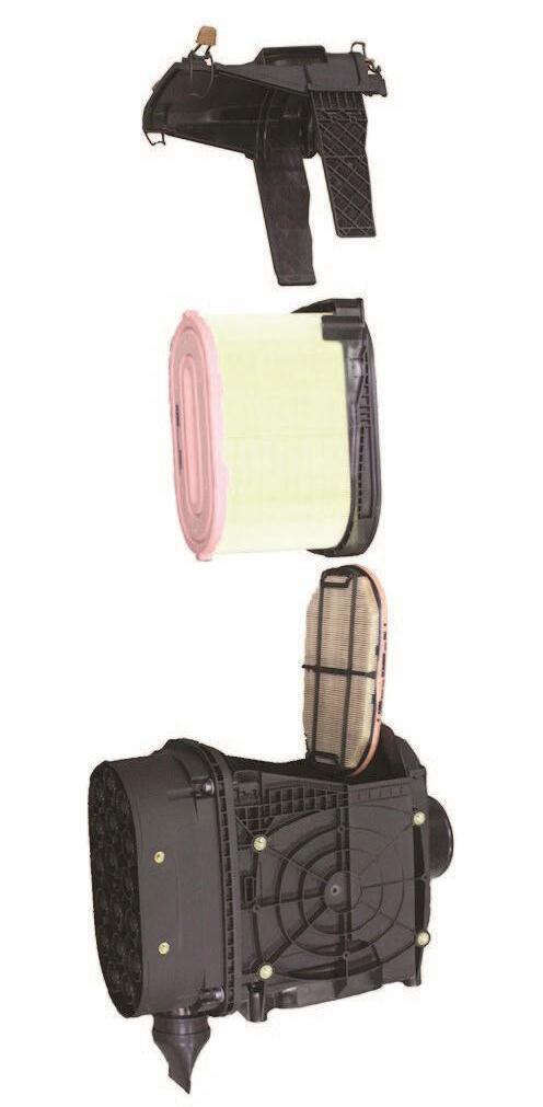
CHANGE AIR FILTER ELEMENT(S)
Primary Element
Secondary Element
Dual-Element Air Cleaner Assembly
The air cleaner assembly consists of a primary filter element and a secondary filter element. Air filter restriction is indicated by the check engine lamp and an error code in the multi-functional display.
The amber check engine lamp will flash for 30 seconds when the ignition switch is turned ON, and an error code will be displayed to indicate the air filter should be replaced.
If the air filter is not replaced and the restriction becomes more severe, the amber check engine lamp will light and stay ON, and an additional error code will display resulting in possible engine power reduction.
The primary element should be replaced whenever indicated by the multi-functional display. The secondary element should be replaced every third time the primary element is replaced, unless the primary element is damaged or the seconadary element is visibly dirty.
Along with a daily check of the restriction indicator, check that the air cleaner intake hose and clamps, and the mounting bracket hardware are properly secure.
Use the following procedure to replace the filter elements:
1. Unlatch the four latch clamps on the top of the air cleaner cover, then lift the cover up from the housing.
Outer Element Removal
1. Carefully lift the outer element out of the housing. Never remove the inner element unless it is to be replaced.
2. Clean out any dirt built up in the housing. Leave the inner element installed during this step to prevent debris from entering the engine intake manifold.
3. Use a trouble light inside the outer element to inspect for bad spots, pinholes or ruptures. Replace the outer element if any damage is noted. The outer element must be replaced if it is oil- or soot-laden.
NOTE: Cleaning the outer element is not recommended.
Inner Element Removal
NOTE: Replace the inner element only if it is visibly dirty or if the outer element has been replaced three times.
1. Before removing the inner element from the housing, clean out any dirt built up in the housing. Leave the inner element installed during this step to prevent debris from entering the engine intake manifold.
2. Remove the inner element.
Element Reinstallation
1. Check the inside of the housing for any damage that may interfere with the elements.
2. Be sure that the element sealing surfaces are clean.
3. Insert the element(s), making sure that they are seated properly.
4. Secure the cover to the housing with the four latch clamps.
5. Check the hose connections and make sure they are all fitted and tightened properly.
NOTE: Periodically inspect intake system tubes, rubber elbows and connections. Inspect for cracks, loose fits and loose clamps. Tighten or replace as needed. Intake system must be air tight.
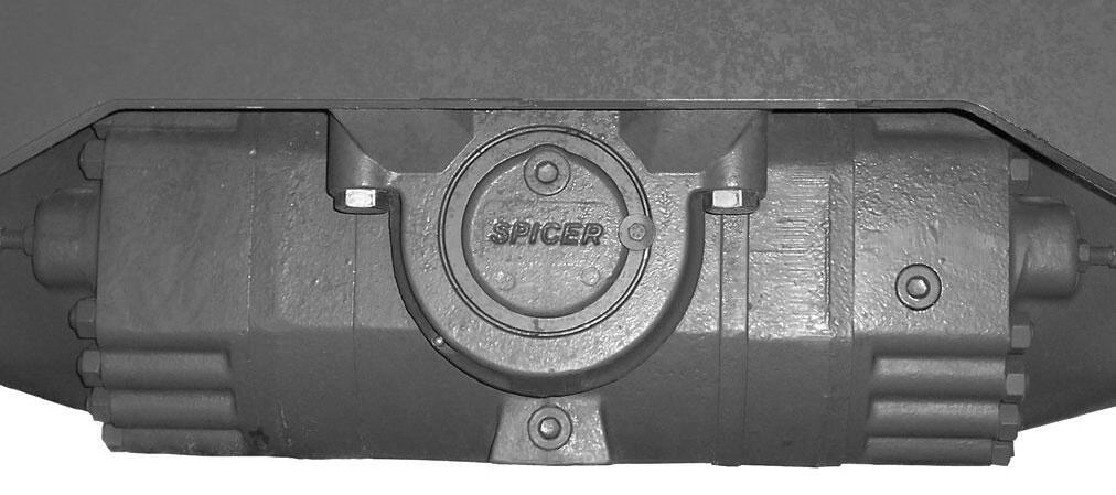
Change Axle Differential And Planetary Oil
Differentials
1. Remove the three drain plugs and drain the used oil. Replace the drain plugs (see illustration).
IMPORTANT: DO NOT discharge oil onto ground. Catch and dispose of per local waste disposal regulations.
2. Remove the fill/check plug. Fill the differential with fresh oil as specified in the Lubrication chapter. When the oil flows from the check hole, replace the plug. Wait 10 to 15 minutes and repeat this process until the axle is full. Repeat this procedure with the other axle.
Axle Planetary Hubs
The hubs have one plug each used for draining and filling (see illustration).
1. Position the wheel until the oil level arrow points down. Remove the drain/fill plug and allow the oil to drain. Replace the plug.
IMPORTANT: DO NOT discharge oil onto ground. Catch and dispose of per local waste disposal regulations.
2. Re-position the hub so the oil level arrow is horizontal. Fill with fresh oil as specified in the Lubrication chapter. When the oil runs out, install the drain/fill plug.
Repeat this procedure on the three remaining hubs.
Check Fan Belt And Fan Hub Condition
Remove the Fan belt and check fan belt for wear , cut or cracks If the belt shows wear or cuts, it should be replaced. Order a replacement belt from your Manitou Group dealer.
With fan belt removed, check the fan hub for wobble or excessive end clearance.
Check Exhaust System
Examine the entire exhaust system for possible holes and leaks. Re-tighten any loose clamps and make sure the manifold outlet gasket is not leaking.
Check Radiator Pressure Cap
Make sure the radiator cap is a 1.1 bar (16 psi) pressure cap. Inspect the rubber seal for damage. Replace it if damage is visible. Inspect the radiator filler neck for cracks or other damage.
An incorrect or malfunctioning radiator cap can result in the loss of coolant and the engine running hot.
NOTE: Pressure checks should be made with engine at low idle.
NOTE: Perform all other service requirements up to this point, as well as the following:
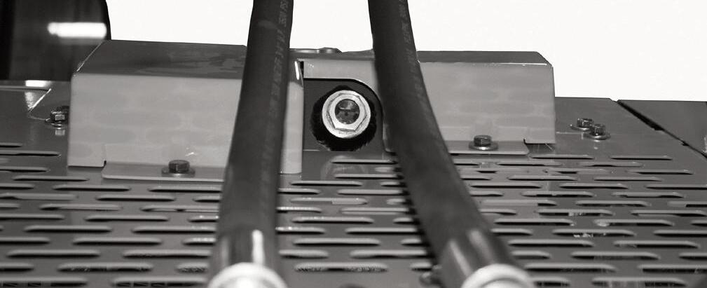
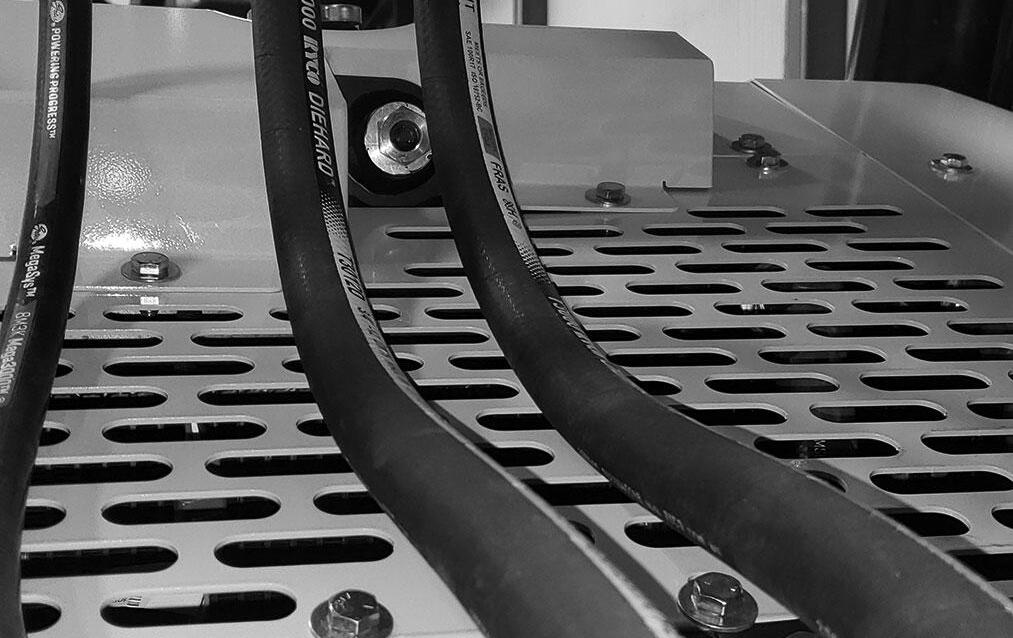
Check Hydraulic System Relief Pressures
Pressure settings for relief valves are pre-set at the factory. Three test ports are provided in the flow divider located on the right inside frame rail under the mid hood access cover.
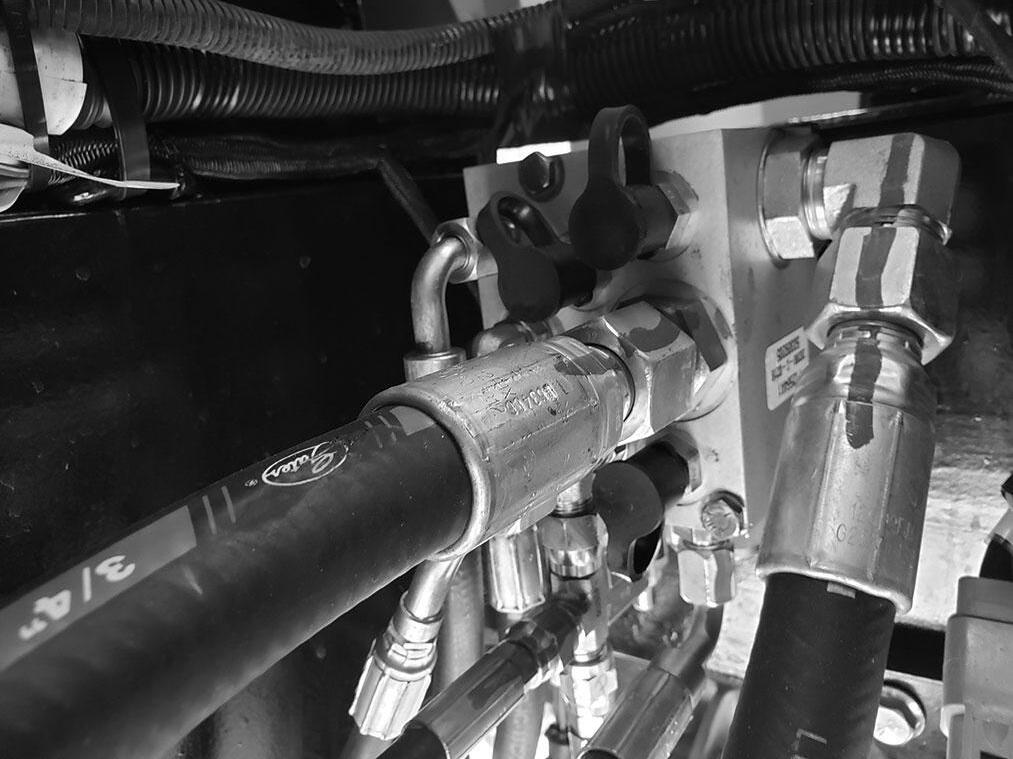
Before conducting any test port pressure checks, check the engine speed. Engine speed must be 1100 rpm at low idle and 2300 rpm at high idle.
Steering Relief Pressure
Plug a 207 bar (3000 psi) oil-or liquid-filled gauge onto the test port labeled ”SP.” Cramp the steering fully to the right or left. The gauge should read 172 bar (2500 psi ).
Joystick and Parking Brake Release Pressure
Plug a 70 bar (1000 psi) gauge onto the port labeled “JP.” With the engine running, the gauge should read 24 bar (350 psi).
Main Relief Pressure
Plug a 207 bar (3000 psi) oil-or liquid-filled gauge onto the test port labeled “MP.” Fully retract the boom over the relief valve. The gauge should read 207 bar (3000 psi).
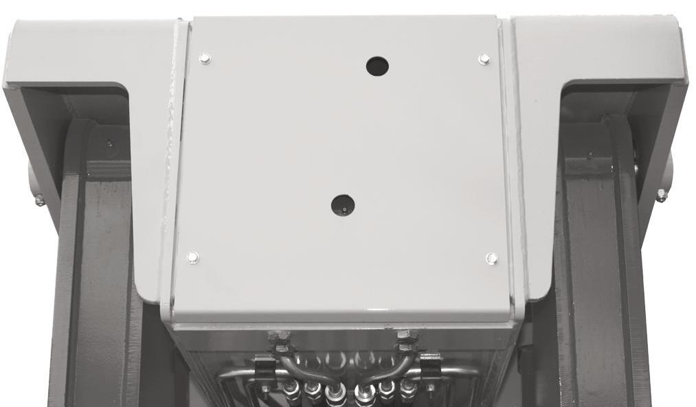
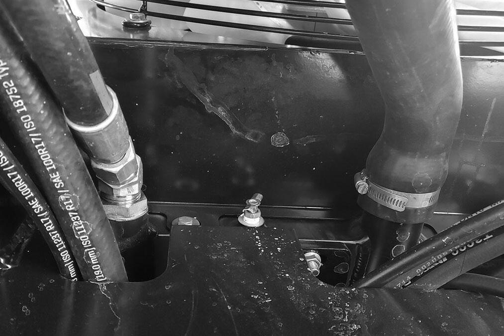
Change Hydraulic Reservoir Oil And Strainer
Clean all dirt and debris from around the top of the reservoir, especially around the access cover. Refer to illustration and use the following procedure:
1. Remove the drain plug and drain used oil. Wash or blow off all particles collected on the magnetic drain plug.
IMPORTANT: DO NOT discharge oil onto ground. Catch and dispose of per local waste disposal regulations.
2. Remove the access cover and wash the inlet screen with clean solvent. Remove and wash the sump filter strainer from the bottom inside of the reservoir. If the strainer has any damage, holes, etc., it should be replaced.
3. Flush out the bottom of the reservoir with clean hydraulic oil. Re-install all cleaned components and install the access cover on the reservoir with a new gasket. Clean the filter/breather cap.
4. Fill the reservoir with fresh oil. Follow specifications in the Lubrication chapter of this manual.
IMPORTANT: Hydraulic fluid and filters should be replaced any time contamination is present before the normally scheduled change.
Warning
NEVER use your hands to search for hydraulic fluid leaks. Escaping hydraulic oil under pressure can have sufficient force to penetrate the skin. Before applying pressure to the hydraulic system, be sure all connections are tight and lines and hoses are not damaged. Use a piece of wood or cardboard to search for suspected leaks. If injured by escaping hydraulic oil, see a doctor familiar with this type of injury at once or gangrene may result.
Change Radiator Coolant
Drain old coolant, and fill with recommended coolant.
Warning
Remove the radiator cap only when the engine is cool, or painful burns could result.
1. Loosen the radiator cap to its stop to release any pressure in the radiator. Remove the cap when all pressure is bled off.
2. Place a collection container with a 5 gallon capacity under the right end of the radiator.
IMPORTANT: DO NOT discharge coolant onto ground. Catch and dispose of per local waste disposal regulations.
3. Open the radiator drain cock (A) to drain the radiator.
4. When coolant is completely drained, Close the radiator drain cock.
5. Slowly add coolant to the radiator until the sight glass is filled with coolant.
IMPORTANT: Fill the cooling system with a low silicate ethylene glycol based coolant mixed with quality water and supplemental coolant additives (SCAs) suitable for heavy-duty diesel engines. See the engine manual for additional information.
7. Inspect the radiator cap seal before installing it. Replace it if it appears to be damaged.
8. Start the engine and run it until the engine reaches operating temperature. Check the coolant level through the sight glass. If the coolant is low, allow the engine to cool before removing the radiator cap to add coolant.
NOTE: Check the engine temperature gauge every minute or two after coolant has been changed. Air pockets can form and it may be necessary to refill the cooling system after a short period of use, as the air will naturally bleed out of the system. Check the sight glass to verify the coolant level before adding coolant.
Check Coolant Hoses And Connections
Check all coolant hoses for cuts, cracks or collapsing. Replace any damaged hoses.
NOTE: The silicone engine coolant hoses used on the machine will exhibit swelling due to the elasticity of the hose.
1. After treatment dosing unit cap.
2. After treatment dosing unit filter equalizing element.
3. Aftertreatment dosing unit filter element. Inspect the area around the seal and vent of the aftertreatment DEF dosing unit filter cap for signs of leakage.
DEF leaks leave a white deposit. If deposits are found, see the Clean and Inspect for Reuse section in this procedure.
Warning
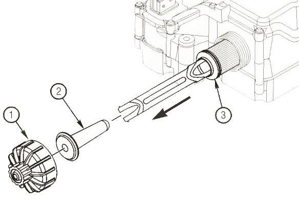
Change Diesel Exhaust Fluid Dosing Unit Filter
NOTE: Machines with the 74 hp engine do not use Diesel Exhaust Fluid and will not have a filter to service. This service procedure is only for machines equipped with the 120 hp engine.
The DEF dosing unit is located on the backwall of the battery compartment behind the DEF tank. The filter is located on the bottom of the dosing unit. Access to the filter can be gained through an opening in the battery compartment floor.
The after treatment DEF dosing unit filter consists of the following components:
Diesel exhaust fluid (DEF) contains urea. Do not get the substance in your eyes. In case of contact, immediately flush eyes with large amounts of water for a minimum of 15 minutes. Do not swallow. In the event the DEF is ingested, contact a physician immediately. Reference the Materials Safety Data Sheet (MSDS) for additional information.
Warning
The diesel exhaust fluid (DEF) line connecting the aftertreatment DEF dosing unit to the aftertreatment DEF dosing valve is under low pressure and should not be disconnected while the engine is running or before the system has completed the purge process after engine shutdown. Disconnecting the DEF line while under low pressure could cause DEF to spray.
DEF Dosing Unit Filter Removal
NOTE: Do not disconnect the vehicle batteries until the DEF dosing system has completed the purge cycle. Before beginning to remove and/or disconnect any components, wait at least five minutes after the keyswitch is turned OFF for the aftertreatment DEF dosing system to purge the DEF from the system. The purge cycle is an automatic process and does not require intervention to occur. The aftertreatment DEF dosing unit will create an audible pumping noise during the purging process.
Turn the battery disconnect switch to OFF and remove the key, then follow these removal instructions:
NOTE: There may be residual DEF in the filter housing. A collection container placed below the DEF filter cap is recommended.
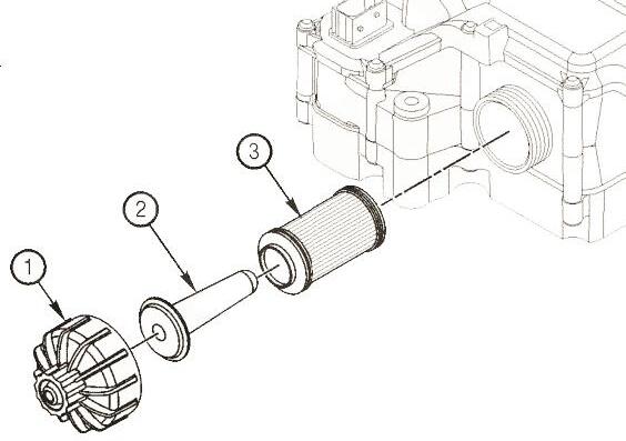
1. Unscrew the DEF filter cap (1). A 27 mm wrench can be used on the cap to aid in removal.
2. Remove the aftertreatment DEF filter equalizing element (2).
3. Remove the old aftertreatment DEF dosing unit filter element (3). A disposable service tool is included with the filter to aid in filter removal. Use the appropriate end of the tool, depending on the color of the plastic on the filter. When inserting the tool, a "click" sound can be heard which indicates proper engagement with the filter.
Clean and Inspect DEF Cap for Reuse
1. Inspect the aftertreatment DEF dosing unit filter cap for cracks or holes that could create a DEF leak path.
2. Check the condition of the threads on the aftertreatment DEF dosing unit cap.
3. If the threads are damaged, replace the aftertreatment DEF dosing unit filter cap.
4. Inspect the aftertreatment DEF dosing unit threads. This is especially important if the aftertreatment DEF dosing unit cap was damaged.
5. If the aftertreatment DEF dosing unit threads are damaged, replace the entire aftertreatment DEF dosing unit.
NOTE: Never operate the vehicle with the DEF cap removed.
Clean the aftertreatment DEF dosing unit cap and threads on the dosing unit with warm water and a clean cloth.
DEF Dosing Unit Filter Installation
Slide the DEF filter equalizing element (2) into the DEF filter cartridge (3).
Insert the assembly into the aftertreatment DEF dosing unit.
Install and tighten the cap (1). A 27 mm wrench can be used to install and tighten the filter cap. Torque the cap to: 177 in-lb [20 Nm].
Storage
If the Telescopic Handler will not be operated for a period of three months or more, prepare and store it using the following procedure:
NOTE: If the storage area is outdoors or in a harsh environment, the storage procedure should be followed if the Telescopic Handler is to be stored for one month.
Before Storage
NOTE: If the filter element and equalizing element are removed from the aftertreatment DEF dosing unit, they must be discarded and replaced; regardless of condition.
Perform the following prior to placing the machine in storage:
1 Wash the entire machine.
2. Lubricate all grease fittings as described in the Lubrication chapter of this manual.
3. Change engine oil as outlined in the Service and Storage chapter of this manual.
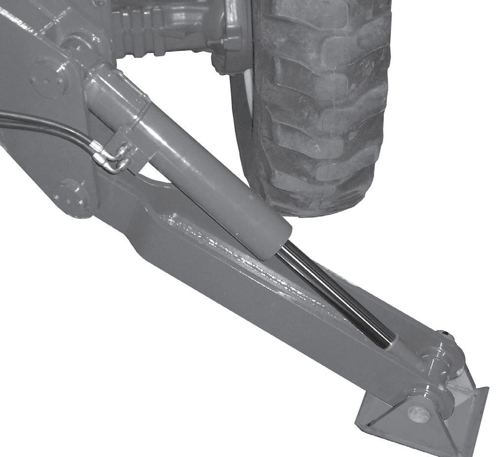
4. Apply grease to all exposed hydraulic cylinder rod areas.
5. Disconnect the battery cable clamps and cover the battery or remove the battery from the machine and store it separately.
6. If the ambient temperature (at any time during the storage period) is expected to drop below freezing, make sure the engine coolant is either completely drained from the radiator and engine block or that the concentration of anti-freeze is adequate to keep the coolant from freezing. Refer to the separate engine manual provided for anti-freeze recommendations and quantities.
During Storage
1. About once each month, connect the battery, check all fluid levels to make sure they are proper, and start the engine.
IMPORTANT: If it is desired to operate the hydraulic cylinders at this time, BE SURE to wipe the protective grease (and any adhering dirt) from the cylinder rods prior to starting the engine. After operating, BE SURE to recoat the cylinder rods with grease if the machine is to be returned to storage.
2. Allow the engine to run until it warms up and then move the machine a short distance to help relubricate the internal parts. Run the engine until the battery is recharged and then shut it off.
After Storage
After removing the machine from storage and BEFORE operating it, perform the following:
1. Change engine oil and filter to remove condensation and other residues.
2. Wipe off grease from cylinder rods.
3. Lubricate ALL grease fittings.
4. Follow the start-up and warm-up procedures outlined in the Operation and Adjustments chapter of this manual.