24 minute read
SAFETY

from Gehl RS SERIES GEN:4 M74 RS6-42 RS8-42 RS8-44 RS9-50 RS10-44 RS10-55 RS12-42 Operator's Manual - PDF


Chapter 5
Indicators And Controls


Guards And Shields
Caution
Become familiar with and know how to use ALL safety devices and controls on the Telescopic Handler BEFORE operating it. Know how to stop the machine operation BEFORE operating it. This Manitou Group machine is designed and intended to be used ONLY with a Manitou Group attachment tool, or a Manitou Group approved accessory or referral attachment tool. Manitou Group cannot be responsible for safety if the machine is used with an unapproved accessory or attachment tool.
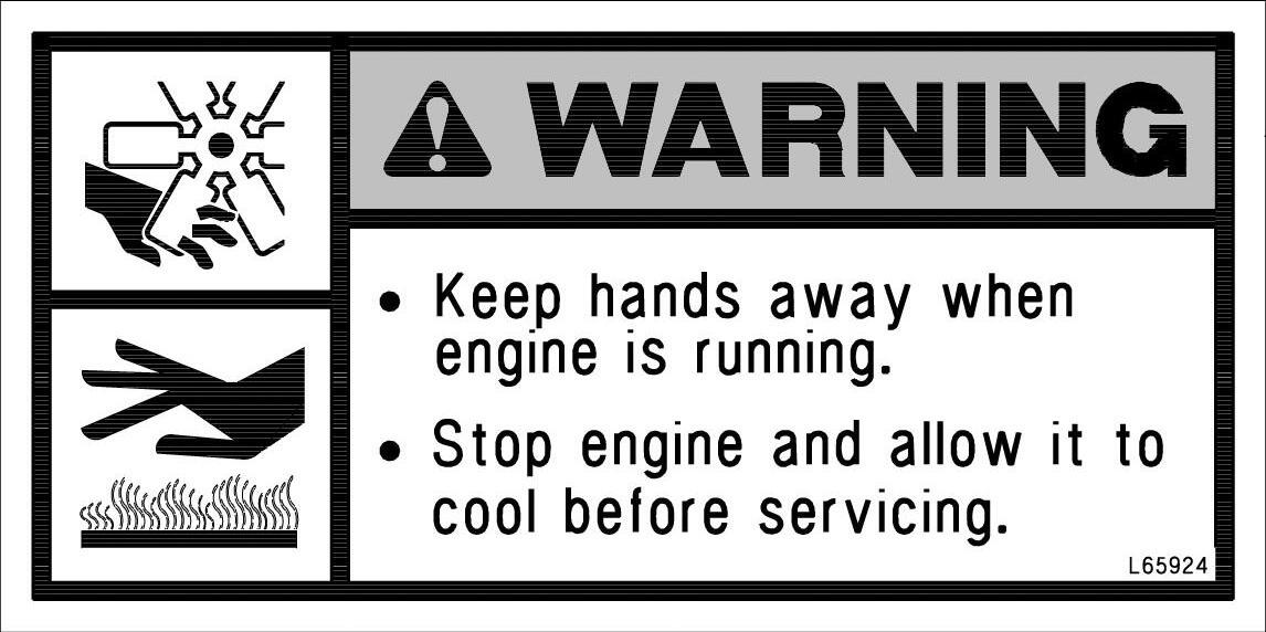
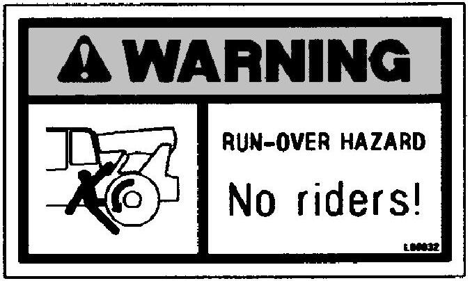
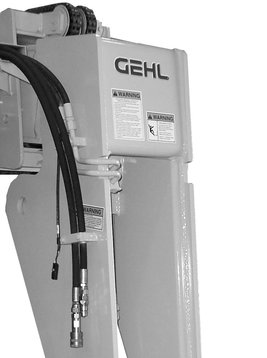
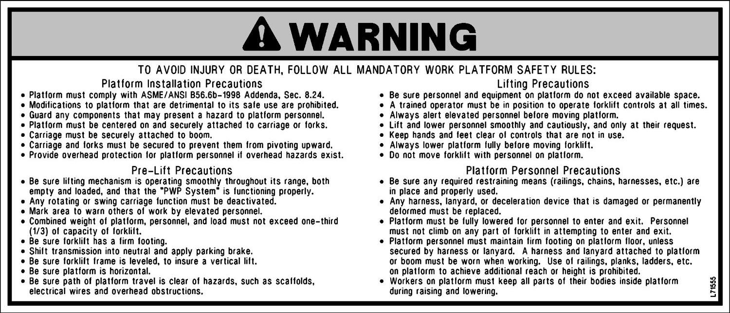
Whenever possible and without affecting machine operation, guards and shields are used to protect potentially hazardous areas. In many places, decals are also provided to warn of potential hazards and to display special operating procedures.
Warning
Read and thoroughly understand all safety decals on the Telescopic Handler BEFORE operating it. DO NOT operate the machine unless all factory-installed guards and shields are properly secured in place.
Ignition Switch
Key Switch OFF: When the key is vertical in the ignition switch, power is disconnected from the battery to the control and instrument panel electrical circuits. This is the only position in which the key can be inserted and removed.

Key Switch ON: When the key is turned one position clockwise from the vertical (OFF) position, power from the battery is supplied to all controls and multi-function display panel electrical circuits. All indicators lamps in the multi-function display will illuminate momentarily as a lamp check.
When the key is in this position, the engine wait to start indicator will stay on until the engine is pre-heated. In colder temperatures the wait to start indicator will stay lit for 3-30 seconds. When the wait to start indicator light goes out the engine can be started.
Start: Turn the ignition switch to this position to activate the starter. Release the ignition switch as soon as the engine starts.
NOTE: If the engine requires repeated attempts to start, the key MUST be returned to the OFF position between starting attempts to prevent battery run down and to reset the air intake heater.
Warning
Do not use starting fluid (ether) with an engine intake air heater system. An explosion can result, which can cause engine damage, injury or death.
Instrument And Switch Panel
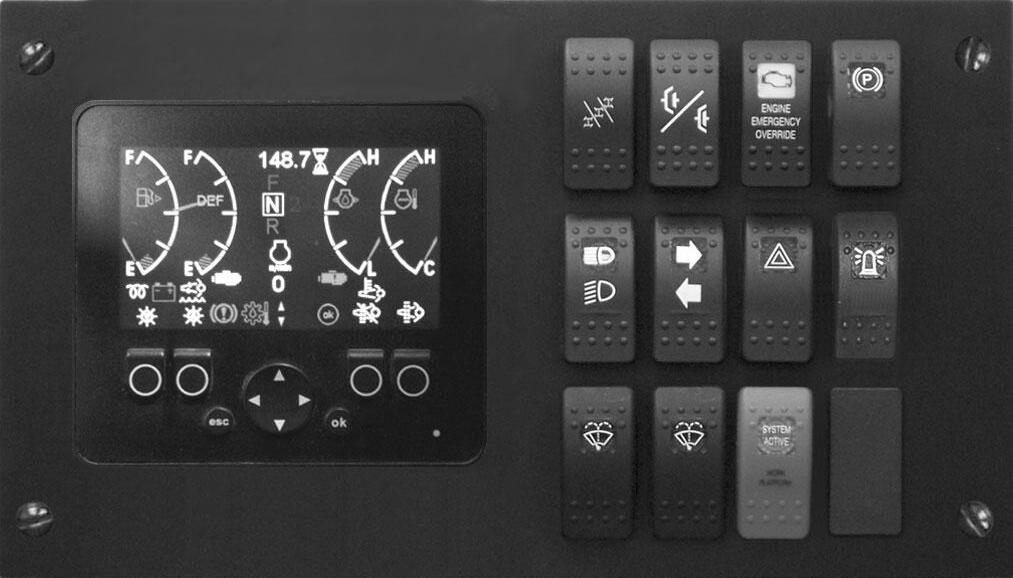
Located to the right of the steering wheel, this panel contains the instrument gauges, indicator lamps and function switches.
Horn: Located in the center of the steering wheel, press the horn button to activate warning sound.
Instrumentation
There are two different multi-functional displays used depending on the engine in the machine.
If the machine is equipped with the 120 hp engine, it will have a multi-functional display that includes a gauge for the Diesel Exhaust Fluid (DEF) level.
If the machine is equipped with the 74 hp engine, it will have a multi-functional display without a Diesel Exhaust Fluid (DEF) gauge.
The fuel gauge includes a white indicator lamp with the percentage of fuel in the tank. If the fuel level is between 12% and 6%, the indicator will flash yellow. If the fuel level is below 6%, the indicator will flash red.
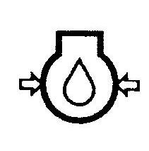
The DEF (Diesel Exhaust Fluid) gauge includes the letters DEF with a percentage of diesel exhaust fluid in the tank. The DEF gauge also includes an amber indicator below the gauge that will illuminate when the level is low. The amber indicator will flash when the level gets very low.

The engine oil pressure gauge includes a white indicator that will flash red if the engine oil pressure is too low or too high.
The engine coolant temperature gauge includes a white indicator that will flash red if the engine coolant temperature is too high.
Pressing the up or down arrow on the (D) button in the bottom center of the multi-functional panel on either display type will scroll through the: engine oil pressure, coolant temperature, engine RPM and voltmeter lamps
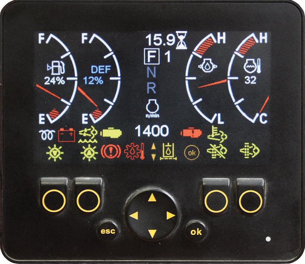
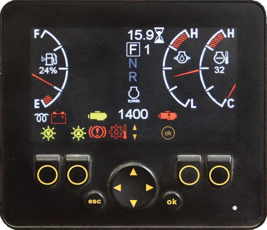
The hour meter is permanently displayed in the top center of the display area.
Button Function
A - Display Brightness: Press this button to make the display dimmer as indicated by the icon above the button. This button is also the back button when navigation the main menu.
B - Display Brightness: Press this button to make the display brighter as indicated by the icon above the button.
C - Escape: Press this button to bring the display screen back to the operation gauges and lamps screen.
D - Scroll: This button is used to scroll through various user initiated functions.
E - OK: Press this button to display the main menu. It is also used to select an option from the main menu. NOTE: Press the escape button at any time to return to the operation gauges and icons screen.
F - Disable Auto Exhaust System Cleaning: (on 120 hp machines only) Press this button to prevent an auto exhaust system cleaning. This button should be used when high exhaust temperature presents a hazard. Pressing the button again will allow auto cleaning.
NOTE: This button will reset to the off position when the ignition switch is turned “OFF” and then back “ON”.
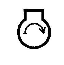
G - Exhaust System Cleaning: (on 120 hp machines only) Press this button to display three requirements needed to perform a stationary exhaust system cleaning. Pressing the down scroll arrow will display instructions on the procedure to perform a stationary exhaust system cleaning.
This button is also used to initiate a stationary exhaust filter cleaning.
On all machines, this button is also used to turn the Routine Maintenance Reminder ON or OFF. Refer to the Routine Maintenance Reminder on the next page for the procedure.
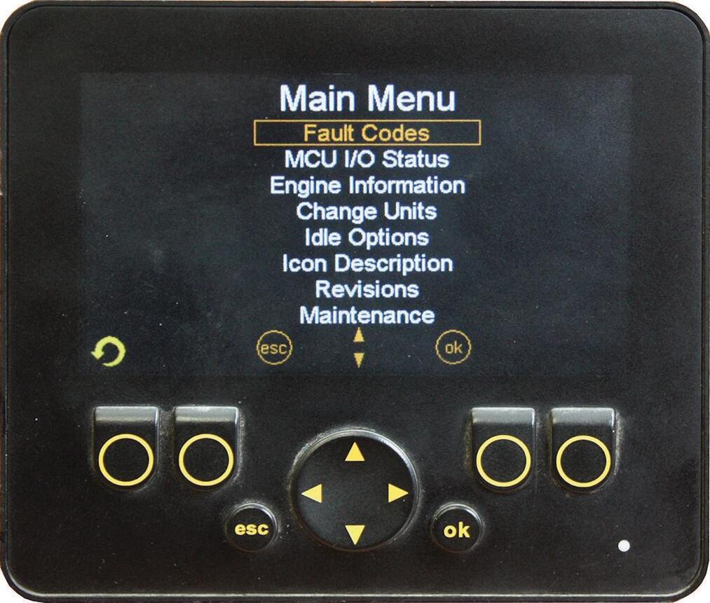
Multi-Function Display Main Menu Options
Press the (E) OK button to display the main menu. Use the (D) scroll button up or down arrows to select a menu function.
NOTE: Press the (C) escape button any time to return to the operation gauges and icons screen.
Fault Codes: Use the up or down scroll button to highlight the fault codes function, then press the OK button. Press the up or down scroll button again to scroll through any additional fault codes.
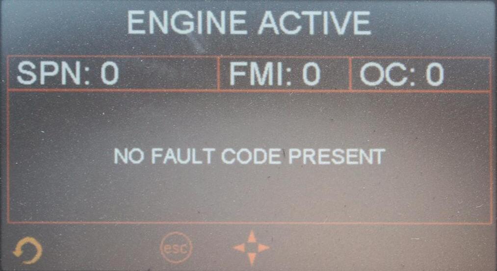
Press the left or right scroll button to switch the display to history or inactive fault codes. Press the (A) back button to return to the main menu.
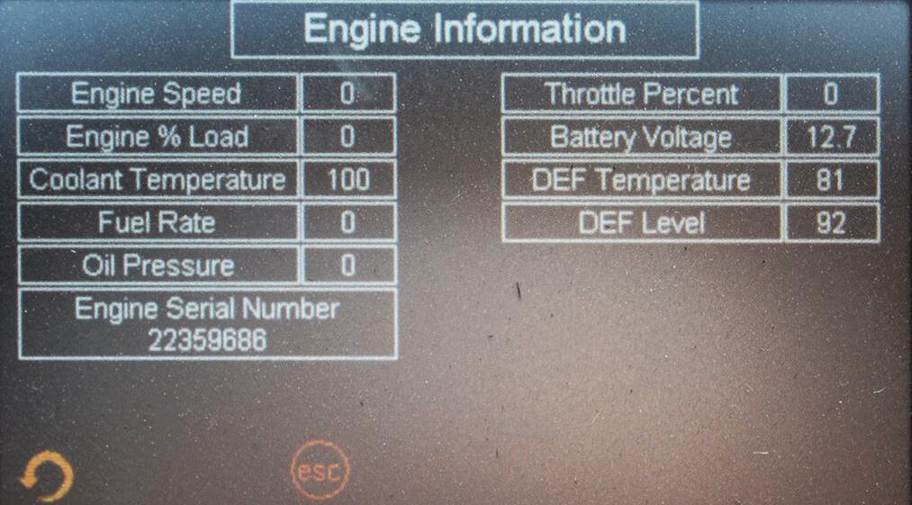
Engine Information: Use the up and down scroll button to highlight the Engine Information function, then press the OK button. This screen will display various engine related information. Press the (A) back button to return to the main menu.
MCU I/O Status: Use the up and down scroll button to highlight the MCU I/O function, then press the OK button. Use the up or down scroll button to select the inputs or outputs. Press the (A) back button to return to the main menu.

Change Units: Use the up and down scroll button to highlight the Change Units function, then press the OK button. Press the up or down scroll button to switch between SAE and Metric units. Press the (A) back button to return to the main menu.
Idle Options: For high elevation operation, an alternate 1400 RPM low idle setting is available for sluggish or low power conditions at low idle.

Use the up and down scroll button to highlight the Idle Options function, then press the OK button. Press the (G) button to select the alternate 1400 RPM low idle setting. Press the (F) button to select the 1100 RPM default setting. Press the (A) back button to return to the main menu.
Icon Description: Use the up and down scroll button to highlight the Icon Description function, then press the OK button. Use the up or down button to scroll through the icon description pages. Press the (A) back button to return to the main menu.
Revisions: Use the up and down scroll button to highlight the Revisions function, then press the OK button. This will display the part number and revision of the multi-function display panel and the MCU. Press the (A) back button to return to the main menu.
Maintenance: Use the up and down scroll button to highlight the Mainteneance function, then press the OK button. The 250 hour mantenance reminder can be disable by pressing the (G) button below 250hr box. This will change the 250hr in the box to OFF. The routine maintenance reminder can be re-activated any time by following the same procedure and pressing the (G) button so that the box reads 250hr. Press the escape button to return to the operation gauges and icons screen.
Wait-to-Start Indicator Lamp: When lighted this lamp indicates that the intake air heater needs to warm the intake air prior to starting the engine.
Alternator Lamp: This red lamp indicates the condition of the electrical charging system. During normal operation, this lamp should be off. If the alternator charge rate is too low, this lamp will come on.
Diesel Exhaust Fluid (DEF) Lamp: (on 120 hp machines only) This amber lamp will illuminate when the DEF level is low, and flashes when the DEF level falls below a very low level. Refill the DEF tank.
Brake Failure Lamp: This red lamp indicates the condition of the service brake systems. The front and rear brakes are on independent systems. If a loss of pressure occurs in either system during normal operation with the brake pedal depressed, this lamp will come on. Failure in one of the brake systems does not affect the operation of the other system. However, the MANDATORY SAFETY SHUTDOWN PROCEDURE (p. 15) should be followed and any necessary repairs made immediately.
Transmission Oil Temperature Lamp: When lighted this red lamp indicates an abnormally high transmission oil temperature. If this lamp comes on during normal operation, a problem may exist in the transmission oil system. Stop the machine immediately and investigate the cause of the problem.
Operation, Exhaust Filter, Engine and Service Indicator Lamps
Travel Direction and Speed Range Indicator: Located in the upper center of the display panel, the selected travel direction will be lighted and the selected travel speed will be displayed to the right of the direction indicator.

Neutral to Start Indicator: This indicator will display in the lower right portion of the display panel when the travel direction is not in the “N” (neutral) position when attempting to start the engine. Switch the travel direction to “N” (neutral) to start the engine.

Check Engine Lamp: This amber lamp will illuminate when there is an engine or exhaust filter related error.
Stop Engine Lamp: This red lamp will illuminate when an engine or exhaust filter condition exists that could cause engine or exhuast filter damage. Shut down the engine as soon as it is safe to do so.


High Exhaust System Temperature Lamp: (on 120 hp machines only) This amber lamp will illuminate due to higher than normal exhaust temperature during an exhaust system cleaning. The operator should ensure the exhaust outlet is not directed at any flammable or combustible surfaces.

Exhaust System Cleaning Stop Lamp: (on 120 hp machines only) This amber lamp will illuminate when the SCR system cleaning button (F) has been pressed to prevent an exhaust cleaning event.
Exhaust System Cleaning Lamp: (on 120 hp machines only) This amber lamp will illuminate when the exhaust system is unable to complete an automatic Exhaust System Cleaning. The lamp will flash when a stationary exhaust system cleaning is initiated by pressing exhaust filter cleaning button.
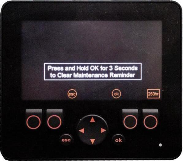
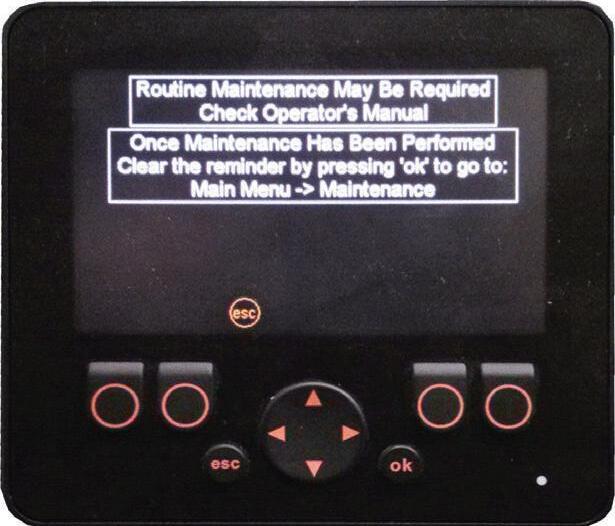
Routine Maintenance Reminder: After every 250 hours of operation, the routine maintenance reminder shown below will display in the multi-functional panel when the ignition key is turned to the ON position. The reminder will display for 15 seconds then return to the normal operation screen.
lowing the same procedure and pressing the button so that the box says 250hr.
Switch Panel
The switch panel contains three rows of switches for the operation of standard and optional equipment on the telescopic handler.
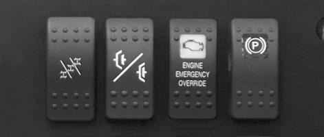
Top Row Switches
Switches have graphic symbols to indicate function and effect. The following descriptions start with the first switch on the left.
Refer to the Service and Storage chapter to determine the required maintenance for the hours on the machine. Once the maintenance has been performed, the routine maintenance reminder can be cleared by navigating to the maintenance menu. Once you select the maintenance menu, clear the message by pressing and holding the OK button for 3 seconds.
NOTE: Some switches are optional and may not be on machine.
A - Steering Mode: This 3-position switch is used to select among the three steering modes. The upper position engages the 4-wheel-steer mode. This mode provides all-wheel steering, used for making tighter turns, usually on a jobsite. The center position engages the 2wheel-steer mode. This mode provides front-wheel steering only, used for higher speed travel. The lower position engages the crab-steer mode. This mode is used when a small amount of side shift is needed for picking or placing a load.
NOTE: The rear wheels are not self-centering. Make sure all wheels are in a straight-ahead position before changing the steering mode.
Any of the steering modes can be used in forward and reverse travel. The operator should learn to anticipate changes in machine movement if the steering mode must be changed.
B - Clutch Cutout: When activated, this switch allows faster engine acceleration and more power to the hydraulic system, without power to the drive axles, while the service brake pedal is pressed.
The routine maintenance reminder can be disabled by navigating to the maintenance menu. Press the lower right button below the 250hr box. When the button is pushed the box should then say OFF. The routine maintenance reminder can be re-activated any time by fol-
In the “OFF” position, the clutch mechanism of the transmission remains engaged when the brakes are applied. In the “ON” position, the clutch mechanism is disengaged when the brakes are applied.
Normal brake force will hold the machine in position while accelerating the engine to power hydraulic control functions during load placement.
C - Engine Emergency Override Switch: Pressing and holding the bottom of the engine emergency override switch will override an ECU engine shutdown signal.
The switch must be pressed within 30 seconds of the engine shutdown signal from the ECU to prevent undesired shutdown of the engine. Pressing the switch will override the engine shutdown for 30 seconds at a time to move the machine to a safe location and to lower the boom to the ground. If the engine shuts down, the ignition switch must be turned off for 30 seconds and then back on before the engine can be restarted.
NOTE: Holding the switch continously “ON” will not reset the 30-second timer.
Refer to the error fault code displayed in the multifunction display to determine the cause of the engine shutdown signal.
D - Parking Brake: When the machine is parked, this switch should be pressed to actuate the parking brake mechanism in the front axle.
Warning
Unattended Machine Hazard
Activate parking brake switch and lower attachment tool to ground before leaving machine. An unattended machine can move or roll and cause death or serious injury to operator or bystanders.
Periodically check the parking brake operation to maintain adequate holding power. Always be sure the parking brake switch is off when resuming machine operation.
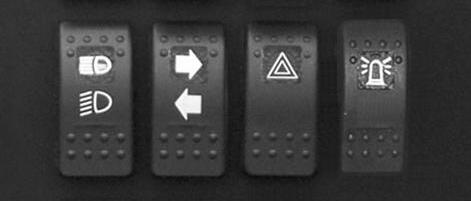
Middle Row Switches
Switches have graphic symbols to indicate function and effect. The following descriptions start with the first switch on the left.
NOTE: Some switches are optional and may not be on machine.
E - Head Lights/Work Lights: Pressing the top of the switch will illuminate the lights mounted on the top of the operator’s station and the red tail lights, for use in forward travel operations. Pressing the bottom of the switch will illuminate the lights at the end of the boom in addition to the lights on the operator’s station, for additional lighting in working operations.
F - Turn Signal: This switch is used to indicate the direction of a turn with the tail lights. Depress the right arrow for a right turn; depress the left arrow for a left turn. Return the switch to the center position after the turn is completed.
G - Hazard: This switch can be activated to make the tail lights flash on and off in case the machine is stalled or temporarily stopped in a traffic area on the road or jobsite.
H - Strobe Light: When a stobe light is installed on the machine, activating this switch will produce a strobe light on and off flashing, for working in conditions that may obscure view of the machine.
Bottom Row Switches
Switches have graphic symbols to indicate function and effect. The following descriptions start with the first switch on the left.

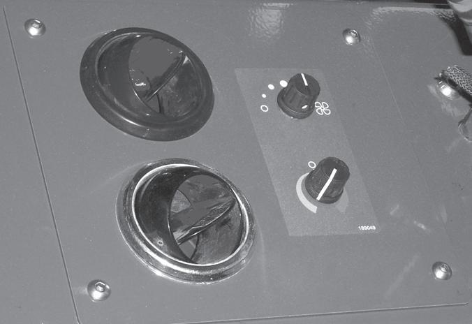
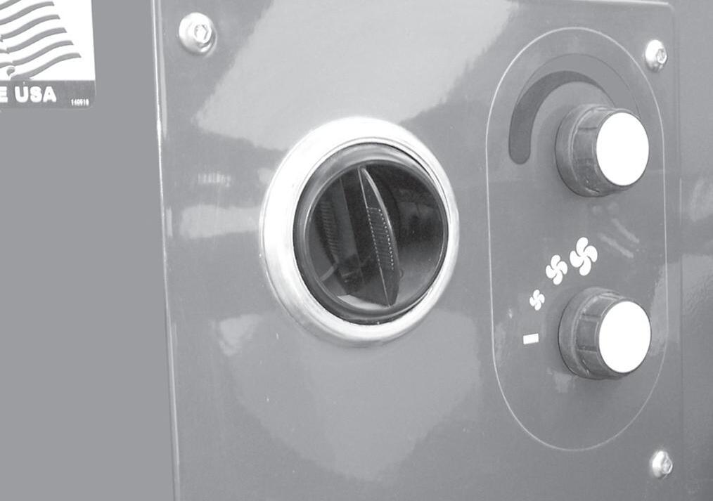
Fan Speed: This knob is located below the temperature control knob. Rotating the knob clockwise will increase the fan speed for increased air circulation.
Heater A/C Controls
NOTE: Some switches are optional and may not be on machine.
I1 and I2 - Wiper/Washer: The windshield and top window of the operator’s station are each equipped with a wiper and washer mechanism. Switch “I1”operates the wiper and washer on the windshield; switch “I2” operates the wiper and washer on the top window.
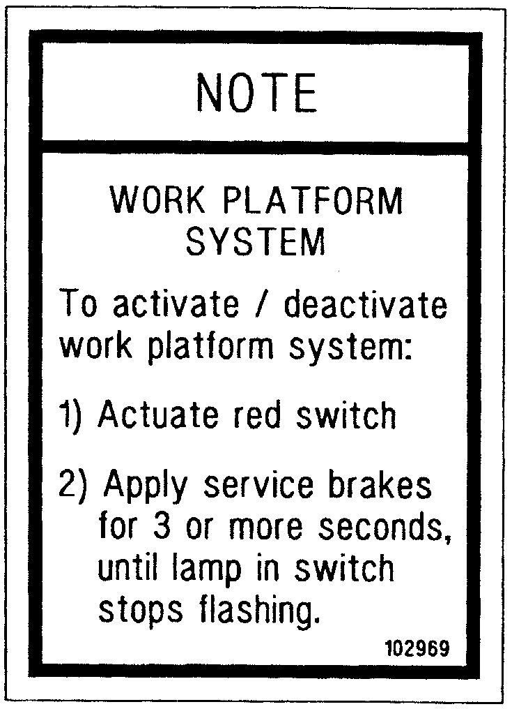
J - Personnel Work Platform: This is a red switch used to activate the Personnel Work Platform (PWP) System. When activated, an amber lamp in the switch will be on.
NOTE: This lamp will flash on and off, indicating that the system is not yet fully functional, until the brakes are held on for three or more seconds.
K - Blank:
Heater Controls
Temperature Control: This is the upper knob located to the left of the steering wheel. This knob is used to adjust the temperature output of the heater. Turning the knob clockwise will increase the temperature output of the cab heater.
Fan Speed: This is the upper knob located to the left of the steering wheel. The fan is in the off position when the knob is rotated completely to the left. Rotating the knob clockwise will switch the fan on and increase the fan speed for increased air circulation.
Temperature Control: This knob is located below the fan speed knob. It is used to adjust the temperature output of the heater A/C unit. Turning the knob clockwise from the midpoint position will increase the temperature output of the cab heater. Turning the knob counterclockwise from the midpoint position will switch the A/C unit on and decrease the temperature output of the cab A/C.
Steering
Turn the steering wheel to the right or left to turn the machine in that direction. The power steering system is designed to provide low effort steering without shock reaction from the tires to the steering wheel.
Throttle Pedal: This pedal, operated by the right foot, controls the engine speed to match power requirements. Pushing down on the pedal increases engine speed; letting up on the pedal decreases engine speed.
Service Brake Pedal: Pressing this pedal activates inboard hydraulic wet-disc-type brakes on all four wheels. Separate front and rear brake systems allow bringing the machine to a safe stop if either system loses pressure.

Fuse and Relay Access: Use the ignition key to open the fuse and relay access door.
Storage Compartment: Use the ignition key to open the storage compartment door under the seat.
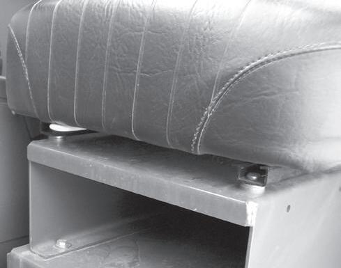
Seat Positioning: The seat is mounted on rails for forward and rearward repositioning, for comfort and to accommodate the operator’s size. A springloaded latch handle “A” under the front of the seat actuates the adjustment mechanism.
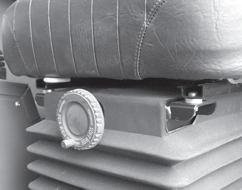
Suspension Seat Option:

In addition to the “A” latch handle for forward and rearward adjustment, this seat has a knob “B” under the front of the seat to adjust the suspension. Turn the knob to the right for a softer ride, and to the left for a firmer ride.
Seat Belt: This machine has a retractable seat belt. Grasp the belt on the left side of the seat, pull the belt over your lap, and insert the belt into the buckle on the right side of the seat until you hear it lock in place.
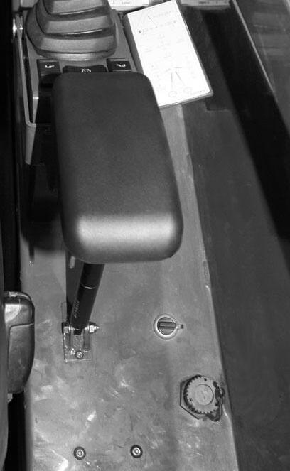
Right Side Panel
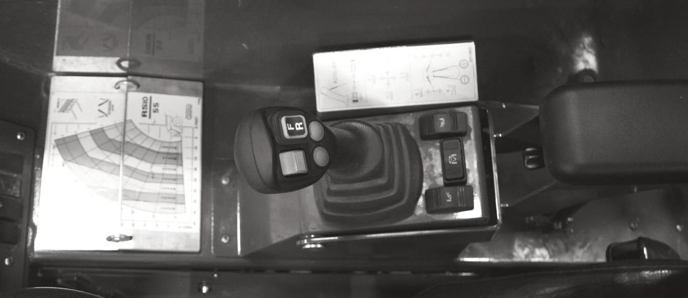
Load Zone Charts: A series of flip charts show lift height and reach limits relative to the load weight being handled with various attachment tools.
Armrest Adjustment Lever: Pull this lever up to adjust the height of the armrest.
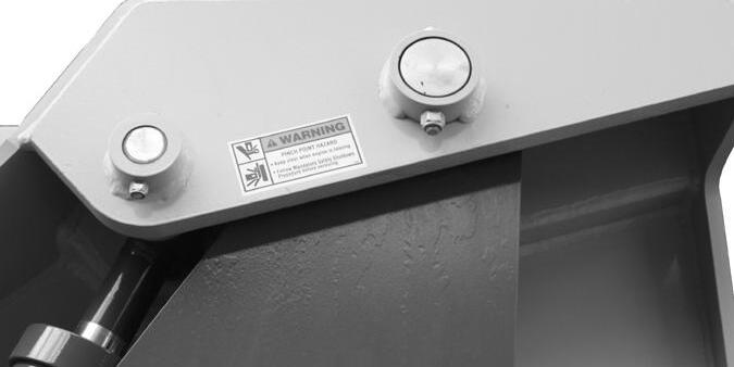
Frame Level Switch: This switch is located to the rear of the multi-function joystick. The machine may be tilted slowly as much as 10° to the left or right to level the frame and boom in relation to the ground.
NOTE: The frame leveling speed will be reduced when the park brake is activated.
Warning
DO NOT level the frame with the boom raised or extended. Only level the frame while stopped and with the boom fully retracted and the attachment raised just enough to clear the ground.
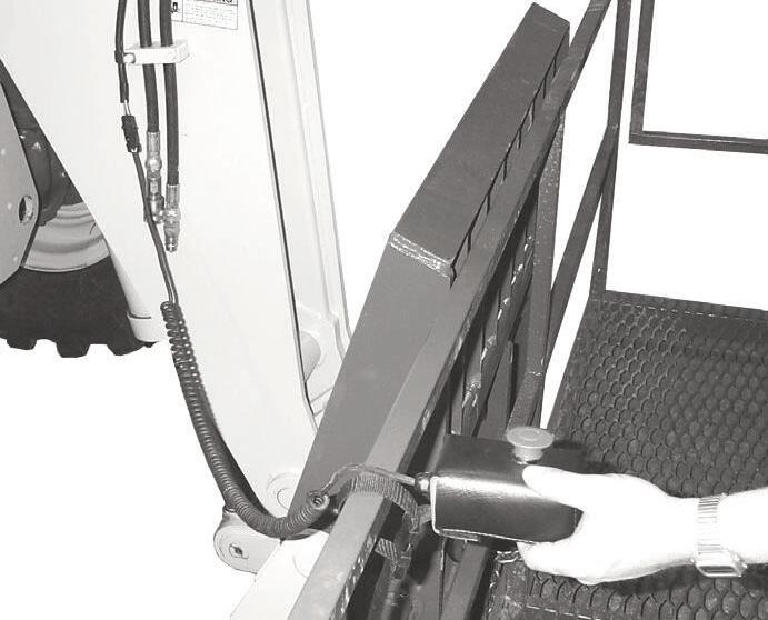
Outrigger Switches: The outriggers are used to provide greater stability in specific applications. Press the left switch forward to lower the left outrigger. Press the right switch forward to lower the right outrigger. Press both switches rearward to raise the outriggers.
Level the frame before lowering the outriggers. Lower the outriggers until the front tires just start to raise.
Warning
For maximum machine stability, never lower the outriggers so that the tires come completely off the ground.
Do not use outriggers on soft or uneven surfaces. Be sure the surface can support the machine and load.
Be sure NO persons or equipment are where the outrigger pads will be positioned.
DO NOT travel with the outriggers extended under any circumstances.
Adequate clearance is required for the outriggers in the retracted position when traveling through doorways or narrow pathways.
DO NOT attempt to use outriggers as a hydraulic jack for maintenance or frame leveling or other similar uses.
Failure to heed could result in death or serious injury.
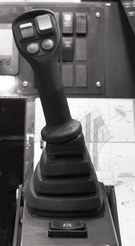
Multi-Function Joystick
The multi-function joystick controls the boom raise/lower and extend/retract functions. Buttons on the joystick control the attachment tilt, auxiliary hydraulics, travel direction and travel speed.
Diagnostic Port
12 Volt Power Port
12 Volt Accessory Power Port: Use this power port to power small electrical devices.
CAN Diagnostic Port: This port is used by service technicians.
A - Boom Raise and Lower: This machine has a hydraulic-type telescopic boom. The boom sections extends by means of a hydraulic cylinder inside the boom.
To extend the boom, move the joystick handle (A) to the right; to retract the boom, move the joystick handle (A) to the left. To raise the boom, move the joystick handle (A) rearward; to lower the boom, move the joystick handle (A) forward.

Warning
Use extreme caution when raising or extending the boom. The Telescopic Handler MUST be level. Loaded or empty, the machine can tip over if it is not level.
ALWAYS place the transmission in neutral, apply the parking brake and keep the service brakes fully applied before raising or extending the boom.
NEVER exceed the specified lift and reach capacities of the machine, or serious machine damage and personal injury may result. Refer to the load charts at the operator’s station or this manual.
If a boom circuit hose fails with the boom up, with or without a load, shut down the machine following the MANDATORY SAFETY SHUTDOWN PROCEDURE. DO NOT attempt repairs. Instead, call your Manitou Group dealer for assistance.
B - Attachment Tilt: To tilt the attachment tool back, move switch (B) downward; to tilt the attachment tool forward, move switch (B) upward. When the operator tilts the attachment tool to a desired angle, that angle will be maintained as the boom is raised and lowered, extended and retracted, until a new angle is set.
Warning
The truss boom and winch attachment tools should ONLY be used to lift and place loads when the machine is in a stationary position. Transporting suspended loads must ALWAYS be done slowly and cautiously, with the boom and load as low as possible. Use taglines to restrict loads from swinging, to avoid overturn.
NEVER use winch for lifting or moving personnel. NEVER exceed the maximum rated capacity of the winch (1360 kg/3000 lbs.) or exceed the load chart rating for winch applications.
DO NOT tilt the truss boom back more than 45o from horizontal. DO NOT attempt to use the optional rotating carriage as a load leveling function. ALWAYS level the frame prior to raising a load.
C - Auxiliary Hydraulics: Move switch (C) on the front of the joystick handle (A) to the left or right to operate the auxiliary hydraulics required on some attachment tools.
D - Travel Direction Switch: The travel direction switch (D) controls forward/reverse travel direction.
l Press the top of the switch (D) to engage forward travel.
l Press the bottom of switch (D) to engage reverse travel.
l The center position of switch (D) will place the machine in neutral.
NOTE: The selected travel direction is shown in the multi-function display.
NOTE: The switch (D) MUST be in the center (Neutral) position before the starter will engage to start the engine.
IMPORTANT: Care should be taken when downshifting or changing direction, because damage to the transmission can occur if shifting is forced or attempted at too high a speed. Allow engine speed to slow before any downshift or directional change is attempted.
NOTE: The backup alarm automatically sounds when the (D) switch is in the reverse position and the park brake is not applied.
E - Decrease Travel Speed: Press the (E) button once to change travel speed to the next lower speed.
F - Increase Travel Speed: Press the (F) button once to change travel speed to the next higher speed.
NOTE: The selected speed range is shown in the multi-function display located to the right of the travel direction indicators.
Function Indicators
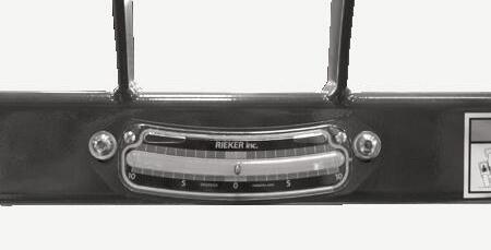
Frame Level Indicator: Located in front of the operator on the ROPS upper cross tube, the position of the ball indicates when the frame is level relative to a sloping ground surface.
Frame Level Indicator
Boom Angle Indicator: Mounted on the left side of the outer boom, the movement of a ball indicates the angle of boom elevation relative to the ground.
Service And Safety Features
Transmission Oil Level: Dipstick is located below the cover on the front section of the main hood.
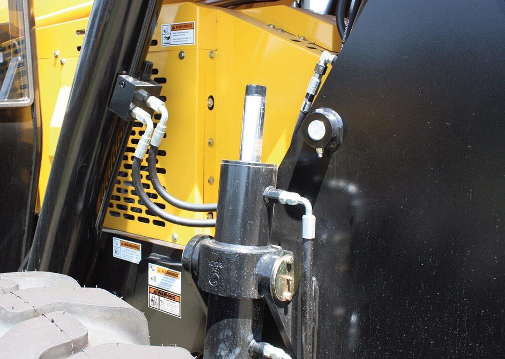
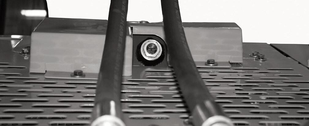
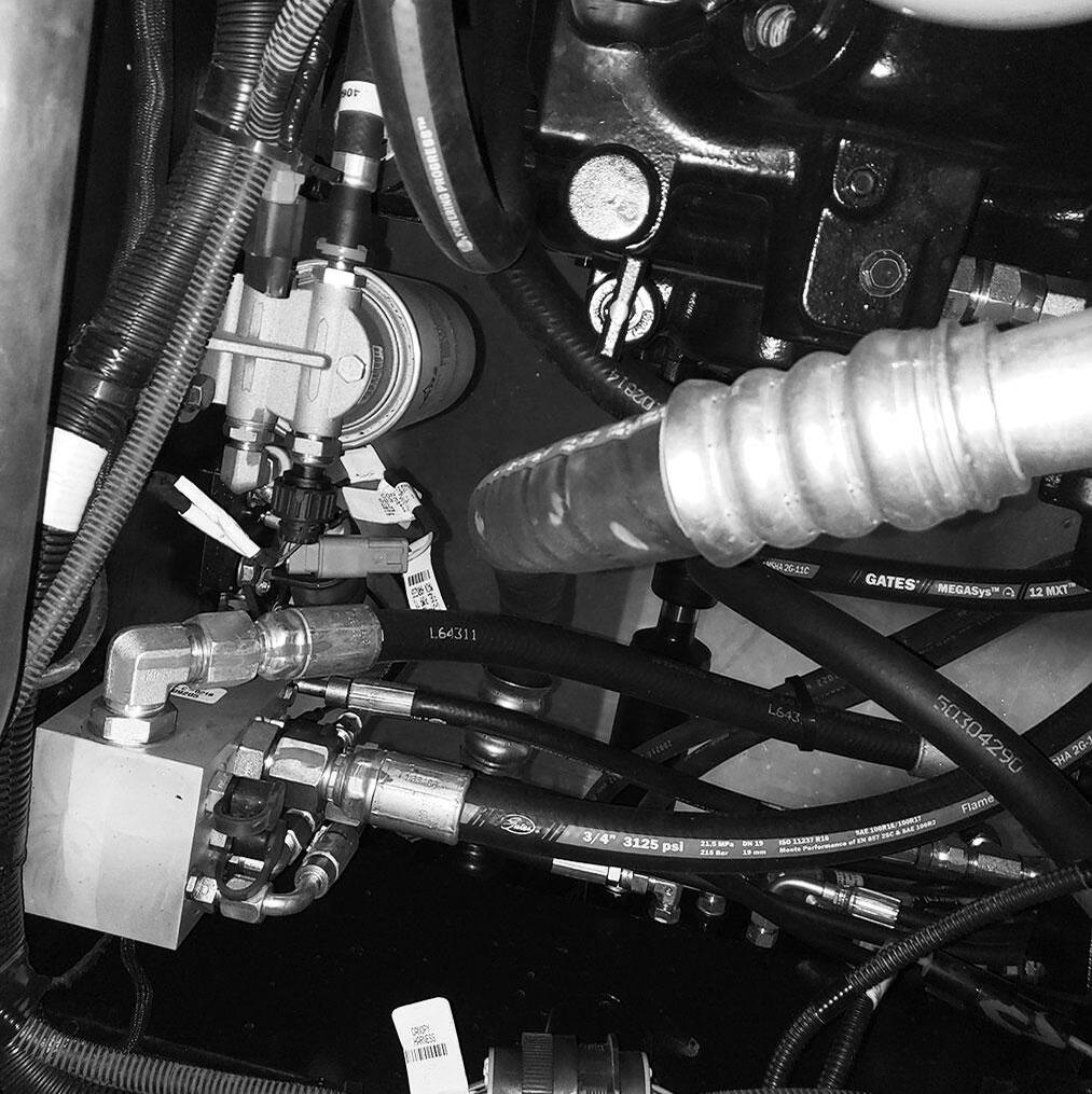
Hydraulic Pressure Test Ports: A gauge can be attached to these ports to check main hydraulic valve, joystick and steering pressures.
Transmission Dipstick
Hydraulic Test Ports
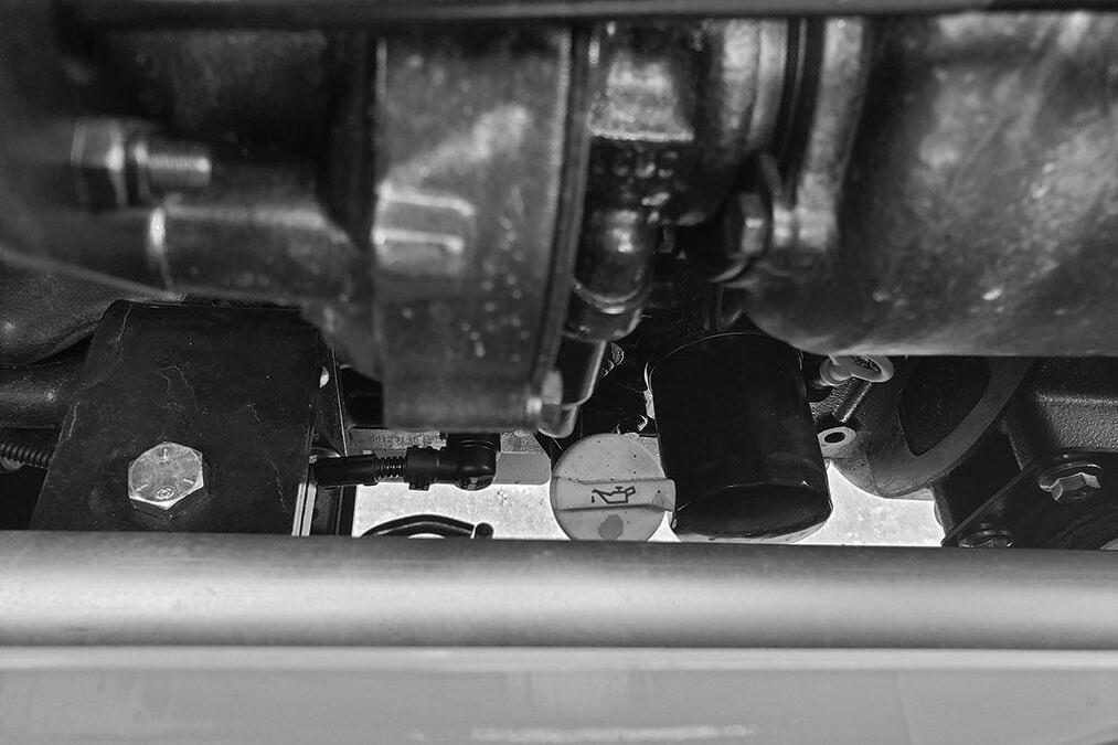
Engine Oil Level and Fill: The dipstick and oil fill are located on the right side of the engine behind the main hood access door. An alternate engine oil fill is on the top engine cover.
Engine Oil Filter
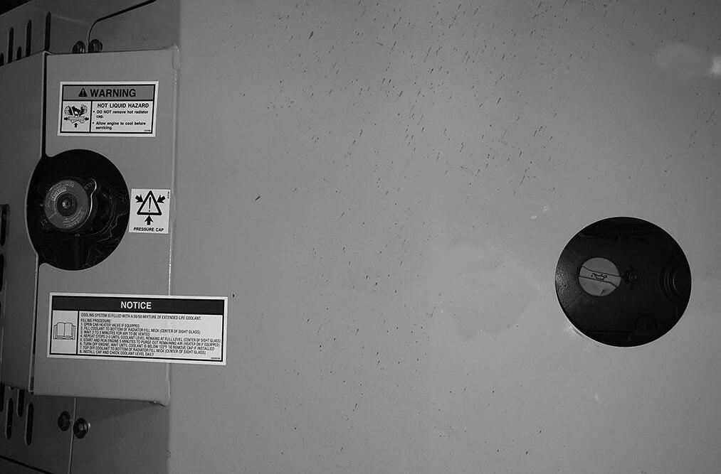
Radiator Sight Glass
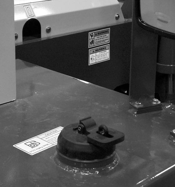
Radiator Cap
Alternate Engine Oil Fill
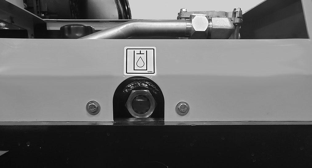
Hydraulic Reservoir Oil Level and Fill Cap: The sight gauge on the side of the reservoir indicates the level of the hydraulic oil. The fill cap is accessible by removing the cover of the front hood section.
Hydraulic Oil Fill Cap
Engine Oil Fill
Engine Oil Dipstick
Coolant Level: Coolant level can be checked through the sight glass on the back side of the radiator. Coolant can be added through the radiator cap located in the top rear opening on the main hood.
Hydraulic Oil Level Sight Gauge
Air Cleaner Restriction: Air cleaner restriction is indicated by the check engine lamp and an error code in the multi-functional display.

Backup Alarm and Light: Located inside the rear frame cover, the backup alarm produces a loud warning sound and the backup light comes on when the park brake is off, and the machine is in reverse.
Backup Alarm Backup Light
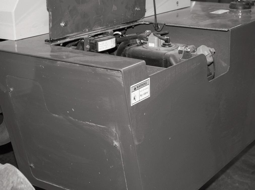
Side-View Mirror: Located on the front outside corner of the fuel tank, this mirror provides the operator with a view toward the rear of the machine.
Battery Compartment: The batteries are located in the compartment on the right side of the machine to the rear of the fuel tank. Open the top access door using the ignition key if locked to check the electrolyte level. Remove the access panel to the rear of the battery compartment to remove the batteries.
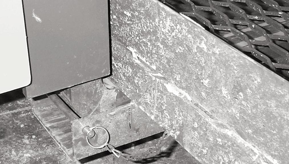
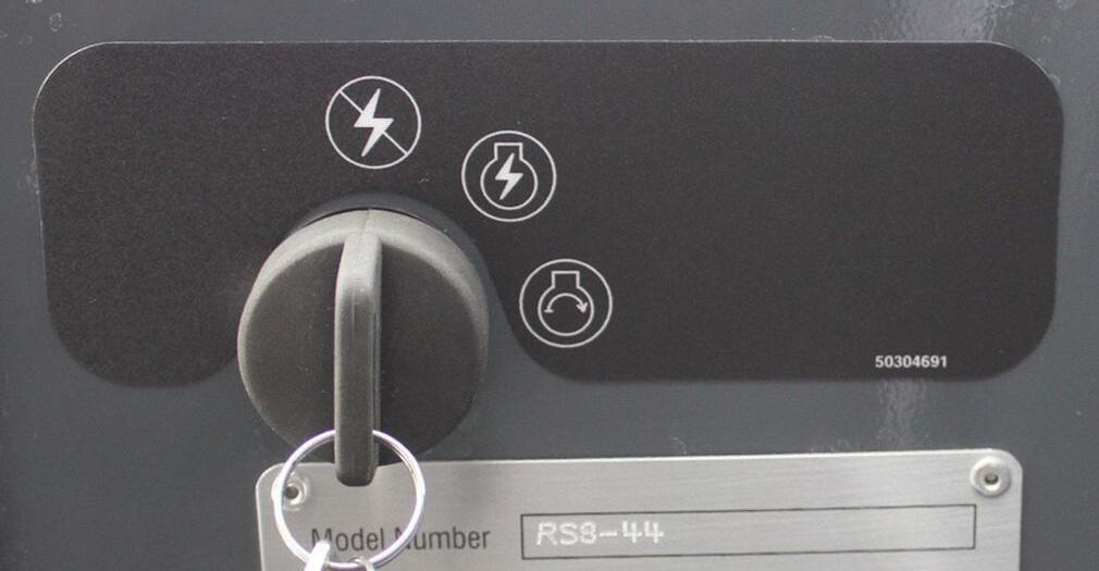
Battery Disconnect Switch: The battery can be disconnected from the electrical system by turning the disconnect switch key to the OFF position.
IMPORTANT: Allow at least 2 minutes after turning off the ignition before disconnecting the battery or turning off the battery disconnect switch. Battery power is needed for the ECM to shutdown which continues after the ignition is turned off.
IMPORTANT: Wait at least 2 minutes after the keyswitch is turned OFF before disconnecting the battery or turning off the battery disconnect switch. Battery power is needed for the aftertreatment DEF dosing system to purge the DEF from the system which continues after the ignition is turned off.
Windshield Washer Fluid Reservoir: The windshield washer reservoir is located inside the battery compartment. Open the top access door to check the fluid level and refill if needed.
Battery Compartment Fuse and Relay: This compartment is located on the right side of the machine to the rear of the fuel tank. Use the igniton key to open the locked door to gain access to the fuses and relays.

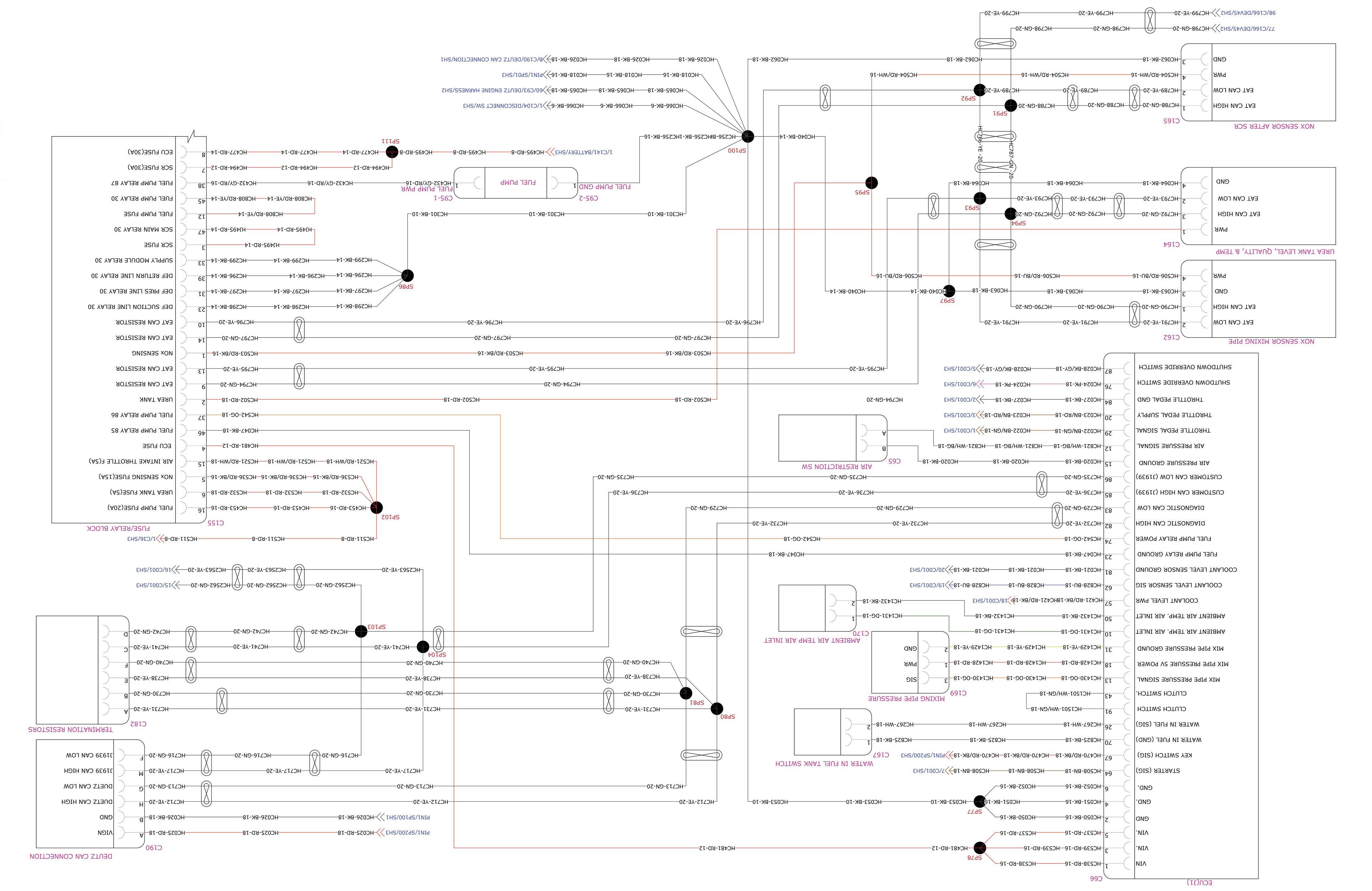
Battery Compartment Fuse and Relay Functions: (on 120 hp machines only) Refer to the illustration and following description for the fuse and relay functions.
FUSES:
1. 30 AMP fuse: ECM Power
2. 30 AMP fuse: SCR
3. 5 AMP fuse: DEF Tank
4. 15 AMP fuse: NOx Sensing
5. 5 AMP fuse: Air in Throttle
6. 20 AMP fuse: Fuel Pump
7. 10 AMP fuse: After Treatment Power (DRT, SCR, DEF)
RESISTORS: a. 120 OHM Exhaust After Treatment b. 120 OHM Exhaust After Treatment
RELAYS:
A. Fuel Pump
B. SCR Main
C. Supply Module
D. DEF Return Line
E. Exhaust After Treatment
F. DEF Pressure Line
G. DEF Suction Line
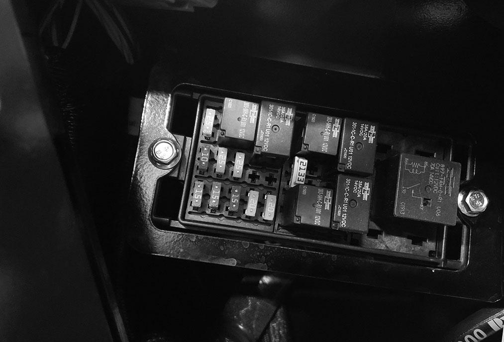
Battery Compartment Fuse and Relay Functions: (on 74 hp machines only) Refer to the illustration and following description for the fuse and relay functions.
To install the cover, place the cover on the box, firmly press each end down untill it clicks, then push the yellow retainers down untill they click.
Operator Station Fuse and Relay Functions: Refer to the illustration and following description for the fuse and relay functions.
FUSES:
1. 20 AMP fuse: Fuel Pump
2. 30 AMP fuse: ECU
RELAYS:
A. Fuel Pump
RESISTOR: a. 120Ω Resistor, J1939 CAN b. 120Ω Resistor, Duetz CAN c. 120Ω Resistor, Duetz CAN
Operator Station Fuse and Relay Compartment: This compartment is located behind a door on the side panel inside the cab. Use the igniton key to open the locked door to gain access to the fuses and relays.
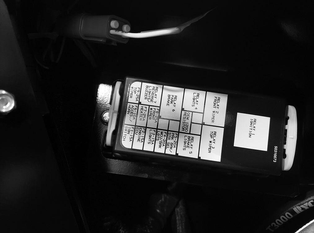
FUSES:
F1. 15 AMP fuse: Ignition Switch.
F2. 15 AMP fuse: Engine ECU.
F3. 15 AMP fuse: Lights, Outriggers.
F4. 20 AMP fuse: MCU, Trans, Brake Lights, Backup Alarm.
F5. 20 AMP fuse: Park Brake, Steer Select, PWP, Frame Level.
F6. 10 AMP fuse: Horn, Accessary Power.
F7. 25 AMP fuse: Heater.
F8. 25 AMP fuse: Front Wiper.
F9. 25 AMP fuse: Top Wiper.
RELAYS:
R1. Ignition Relay.
R2. Front Wiper Relay.

R3. Top Wiper Relay.
R4. Lights Relay.
R5. Brake Lights Relay.
R6. Park Brake Relay.
R7. Reverse Lights and Alarm Relay.
RESISTOR:
NOTE: To remove the fuse/relay box cover, pull the yellow retainer on each end of the box up untill it clicks, then press the tab on each corner in toward the body of the box untill it clicks, the cover can now be removed.
R. OEM 120Ω Resistor.
Optional Features
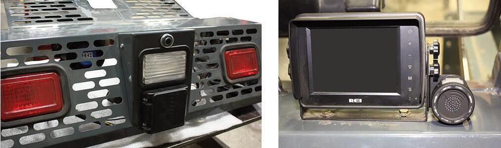
Rear Camera System
This system consists of the rearview camera (1) mounted at the rear of the machine and the viewing monitor (2) mounted on the right side of the dash. This system provides a visual view of the area directly behind the machine.
Attachment Tools
Manitou Group offers a versatile range of attachment tools to meet various lifting and material-handling applications. Contact your Manitou Group dealer for specifications and ordering information.
Accessories
Manitou Group offers a range of special accessories for this machine. Contact your Manitou Group dealer for specifications and ordering information.
Refer to the "Operation and Adjustments" chapter for more information on the rear camera system.
Reverse Radar System
This system consists of the preview sentry (3) mounted at the rear of the machine and the radar display (4) mounted on the right side of the viewing monitor (2). The reverse radar system can be added to the rear camera system for an audible indication of objects to the rear of the machine.
NOTE: All accessories are field-installed unless otherwise noted. Information and parts for installing accessories will be provided by the Manitou Group or Manitou Group Telescopic Handler dealers.
Refer to the "Operation and Adjustments" chapter for more information on the reverse radar system.
Warning
Always use mirrors and look to the rear of the machine before and during backing. Clear any people or obstruction from your path before backing. Rear camera and reverse radar systems are for supplementary use only.
Chapter 6
Operation And Adjustments
General Information
Caution
BEFORE starting the engine and operating the Telescopic Handler, review and comply with ALL safety recommendations in the SAFETY chapter of this manual. Know how to STOP the machine before starting it. Also, BE SURE to fasten and properly adjust the seatbelt.
ENGINE BREAK-INA new engine does not require extensive “break-in.” However, for the first 100 hours of operation:
· Allow the engine to idle for a few minutes after every cold start.
· DO NOT idle the engine for long periods of time.
· DO NOT operate the engine at maximum power for long periods of time.
· Vary the engine speed and load.
· Check the oil level frequently, and replenish as necessary with the oil specified in the engine manual.
After the first 100 hours of operation, change the oil and replace the oil filter. Consult the Lubrication chapter or the engine manual for the type of oil to use in the engine. Refer to the Service and Storage chapter for the proper service intervals.
PRE-START WALK-AROUND INSPECTION
It is the operator’s responsibility to perform a pre-start inspect of the machine before the start of each workday. Every pre-start inspection must include more than simply checking the fuel and oil levels. It is a good practice to personally inspect any machine you are assigned to use, even though it has already been put into service by other personnel.
The pre-start inspection is designed to discover if the machine has incurred any damage or is in need of routine service.
Any needed repairs are to be made by a qualified service technician.
Refer to the illustration and checklist on the next two pages for the “Pre-Start Walk-Around Inspection.”