25 minute read
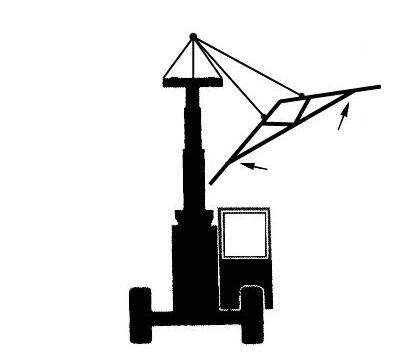
Pre-Start Walk-Around Inspection Illustration

from Gehl RS SERIES GEN:4 M74 RS6-42 RS8-42 RS8-44 RS9-50 RS10-44 RS10-55 RS12-42 Operator's Manual - PDF

PRE-START WALK-AROUND INSPECTION PROCEDURE
Refer to the following illustration and checklist to perform the inspection. Begin with item 1 at the left front of the machine and walk toward the rear of the machine on the left side and around the back and toward the front on the right side of the machine.
Any needed repairs or service noted during the inspection must be performed by a qualified service technician before operating the machine.
The illustration and checklist page can be copied for future pre-start walk-around inspections.

Pre-Start Walk-Around Inspection Checklist
Note the condition of safety decals during the walk-around inspection. Replace missing or illegible safety decals.
o1. Attachment Tool: Check for broken, missing or damaged parts. When using a personnel work platform, check to see if the platform meets ANSI/ITSDF standards and that it is secured to the forks and fork carriage. When using forks, check for welds, cracks or misalignment. Replace the forks in sets when the condition of the forks is questionable.
IMPORTANT: DO NOT use forks that have been repaired by welding.
o2. Attachment Tool Mount: No loose or missing parts; no visible damage.
o3. Attachment Tool Mounting Pins: No visible damage; pin fit is secure and properly lubricated.
o4. Boom Chain: No loose or missing parts; no visible damage; sheave pin fit is secure and properly lubricated.
o5. Boom Sections and Wear Pads: No loose or missing parts; no visible damage or excessive wear.
NOTE: Wear pads that measure 9.5 mm (3/8”) thick or less need to be replaced.
o6. Outriggers (when equipped): Properly secured; pads in downward position; no visible damage; no loose or missing parts; no leaking from the cylinder.
o7. Boom Angle Indicator: Properly secured; no visible damage; bubble is visible.
o8. Tire and Wheel Assemblies: Properly secured; no loose or missing lug nuts; no visible tire damage (cuts or abrasions); proper inflation.
o9. Front and Rear Axles: No loose or missing parts; no visible damage; tie rod end studs locked; no evidence of leaking; properly lubricated.
o10. Operator Compartment: o Seat belt undamaged; operates properly; mounting hardware secure. o Switches and levers undamage; o no loose or missing parts; o load charts properly secured and legible; o levers and switches operate properly; control markings legible; o frame level indicator secured and undamaged, bubble is visible. o11. Lift Cylinder: Properly secured; no visible damage; no evidence of leaking from the cylinder; properly lubricated. o12. Rear Axle Stabilizer Cylinder: Properly secured; no visible damage; no evidence of leaking from the cylinder; properly lubricated. o13. Slave Cylinder: Properly secured; no visible damage; no evidence of leaking from the cylinder; properly lubricated. o14. Stabilizer Switch: Properly secured; no visible damage; no loose or disconnected wires. o15. Boom Pivot Assembly: Properly secured; no visible damage or excessive wear; properly lubricated. o16. Boom Hydraulic Hoses: No visible damage or exterior wear; no evidence of leaking. o17. Rear Light Assembly: Properly secured; no visible damage; no loose or disconnected wires; no malfunctions. o18. Hydraulic Control Valve Assembly: No loose or missing parts; no evidence of leaking; no damaged or leaking hoses. o19. Exhaust System: No loose or missing parts; no visible damage; no obstructions to the outlet. o20. Hydraulic Cooler: No loose or missing parts; no visible damage; no evidence of leaking; cleanliness; o21. Engine Compartment: o Engine oil level, add if needed; o Coolant level, add if needed; o No evidence of engine oil or coolant leaks; o Belts and hoses in good condition, properly secured and adjusted o22. Boom Hose Guards: Properly secured; no visible damage. o23. Engine Air Filter: No loose or missing parts; no visible damage; no obstructions to the evacuator; pre-cleaner free from dirt; restriction indicator proper reading. o24. Battery Compartment: Proper electrolyte level; no loose or damaged cables; no visible damage or corrosion. o25. Fuel Tank: No visible damage; no evidence of leaking; level of fuel; breather cap secure and working. o26. Mirror Assembly: No loose or missing parts; no visible damage; properly adjusted. o27. Hydraulic Oil Reservoir: No visible damage; no evidence of leaking; recommended oil level; breather cap secure and working. o28. Cowling and Latches: All cowling, doors and latches in working condition; properly secure; no loose or missing parts; all components operate properly. o29. Frame Tilt Cylinder: Properly secured; no evidence of leaking; properly lubricated. o30. Frame: No visible damage; no cracked welds; no loose or missing parts. o31. Tilt and Auxiliary Hydraulic Hoses: No visible damage or excessive wear; no evidence of leaking. o32. Attachment Tilt Cylinder: Properly secured; no visible damage; no evidence of leaking from the cylinder; properly lubricated. o33. Boom Mounted Hook (if applicable): Properly secured to boom, no sign of damage to hook or mounting hardware.
Before Starting Engine
Before mounting the operator’s compartment, walk completely around the machine to be sure no one is under, on, or close to it. Let others in the area know you are going to start up. Wait until everyone is clear of the machine before starting it up.
Before starting the engine and running the machine, refer to the Indicators and Controls chapter and become familiar with the various operating controls, indicators and safety features.
Starting The Engine
Warning
ALWAYS fasten the seat belt BEFORE starting the engine. Leave the parking brake applied until the engine is running and you are ready to operate the machine.
The following procedure is recommended for starting the engine:
1. Grasp the handholds and step up into the operator’s compartment.
2. Adjust the seat and fasten the seatbelt.
3. Check that all controls are in their “neutral” positions, except the parking brake switch, which should be in the “ON” position.
4. Turn the key switch clockwise one position to the “ON” position. When the Wait-to-Start indicator lamp in the multi-function display goes out, the engine can be started.
5. Turn the key switch clockwise until the engine starter activates. Release the key switch when the engine starts. If the key switch is released before the engine starts, turn the key switch to the “OFF” position and wait one minute before attempting to start again.
IMPORTANT: Crank the starter until the engine starts. If the engine fails to start within 20 seconds, return the key to the “OFF” position, wait one minute, and try to start the engine. Cranking the engine for longer than 20 seconds will result in premature failure of the starter.
6. After the engine starts, allow several minutes warm-up time before operating the controls. Allow a longer warm-up time in cold weather.
7. Check that indicators are in their normal operating conditions.
8. Verify that there are no fuel, oil or engine coolant leaks, and no abnormal noises or vibrations.
Cold Starting Procedures
The engine is equipped with a block heater. This block heater or other starting aid is required for starting in temperatures below 0°C (32°F). See your Manitou Group dealer for additional starting aids.
Warning
DO NOT use starting fluid on engines equipped with an intake air heater. Starting fluid is highly flammable and may explode, causing serious injury.
If the battery becomes discharged and has insufficient power to start the engine, jumper cables can be used for starting assistance. Refer to the jump starting instructions in the Service and Storage chapter of this manual for safe jump starting procedures.
Stopping
The following procedure is the recommended sequence for stopping the machine:
1. Bring the machine to a stop on a level surface. Avoid parking on a slope, but if necessary park across the slope and block the wheels.
2. Fully retract the boom and lower the attachment to the ground.
3. Idle the engine for at least 3 minutes for gradual cooling.
IMPORTANT: If an Exhaust Filter Cleaning has just been performed, increase the engine idle time to 5 minutes.
4. Place controls in neutral. Apply the parking brake.
5. Turn the ignition switch key to the “OFF” position. Remove the key.

6. Unfasten the seatbelt, and grasp the handholds while climbing out of the operator’s compartment.
7. Wait 2 minutes before turning the battery disconnect switch OFF or disconnecting the battery.
First Time Operation
Make sure the engine is warm, and then go through the following procedures:
Caution
Be sure the area used for test-running is clear of spectators and obstructions. Initially, operate the machine with an empty attachment tool.
Place the travel direction switch on the multi-function joystick in Forward or Reverse and select a speed range by pressing either the increase or decrease travel speed button. Switch off the parking brake and move ahead slowly, while testing the steering and brakes. Stop and operate all boom, attachment tool functions and frame leveling controls, checking for smooth response.
Apply the service brakes, stop the machine and move the travel direction switch to the opposite direction.
Shifting to the next higher gear may be done at any engine speed while the machine is in motion.
DO NOT overspeed the engine when down-shifting. Allow the machine to slow down before shifting to the next lower gear.
Engine Protection System
The engine is equipped with an engine protection system. The system monitors critical engine temperatures and pressures, and logs diagnostic faults when an over or under normal condition occurs. If an out-of-range condition exists and the engine derate action is to be initiated, the operator is alerted by the amber Check Engine Warning lamp. The red Engine Stop lamp flashes when out-of-range conditions continue to worsen. The operator must shut down the engine as soon as it is safe to do so.
Exhaust Filter Cleaning System
NOTE: Information about the Exhaust Filter Cleaning System and procedures related to it pertain to machines equipped with the 120 hp engine only.
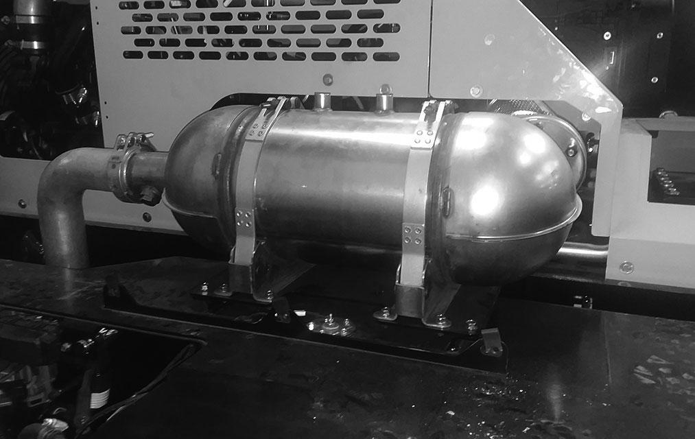
The engine is equipped with a Selective Catalytic Reduction (SCR) system in place of a muffler. The SCR is located under a cover to the right of the engine as shown below with covers removed. The SCR uses diesel exhaust fluid (DEF) to reduce the nitrogen oxide emissions from the exhaust into nitrogen and water.
Under normal machine operation and with the system in AUTO mode, the SCR system requires minimal operator interaction.
To avoid unnecessary buildup of diesel particles or soot in the exhaust filter system;
1. Utilize the Automatic (AUTO) Exhaust Filter Cleaning mode.
2. Avoid unnecessary idling.
3. Use the proper engine oil. See Lubrication chapter of this manual or the engine maual for proper engine oil specifications.
4. Use only ultra low sulfur diesel (ULSD) fuel. See Lubrication chapter of this maual or the engine manual for fuel requirements.
Automatic (AUTO) Exhaust Filter Cleaning
Operating the engine in AUTO Mode allows the ECU to perform intelligent exhaust cleaning as required. The High Exhaust System Temperature (HEST) Lamp will illuminate when the system is actively performing an exhaust filter cleaning. When the exhaust filter cleaning process has completed its cycle, the (HEST) indicator will turn off.
The machine can be operated as normal during the auto exhaust filter cleaning process unless the operator determines the machine is not in a safe location for high exhaust temperatures and disables the auto cleaning process.
To disable the auto exhaust filter cleaning mode, press the Disable Auto Exhaust Filter Cleaning button.
IMPORTANT: It is recommended that the exhaust filter cleaning be in the Auto mode at all times. Auto mode should only be disabled when the machine is not in a safe location for high exhaust temperatures.
If the machine is not able to be moved to a safe location, the operator should temporarily disable auto exhaust filter cleaning. If the machine is located in a safe location, the auto mode should always be enabled.
Stationary Exhaust Filter Cleaning
Stationary exhaust filter cleaning is initiated by the operator. This process allows the system to clean the SCR when the operator previously needed to disable the auto exhaust cleaning process because of specific conditions.
When a stationary exhaust cleaning is initiated by pressing the Exhaust Filter Cleaning button, the Exhaust System Cleaning Lamp will flash indicating the exhaust cleaning is in process. During this process the engine speed will be controlled by the ECU. The machine must remain parked during this process.
Warning
During auto or manual exhaust filter cleaning operations, the engine will run at elevated idle and hot temperatures for approximately 30 minutes. Exhaust gases and exhaust components reach temperatures hot enough to burn people, ignite, or melt common materials.
Servicing the machine or attachments during exhaust filter cleaning can result in serious personal injury. Avoid exposure and skin contact with hot exhaust gases and components.
If the machine is not in a safe location for elevated temperatures, move the machine to a safe location and check for adequate fuel level before beginning the exhaust filter cleaning process.
NOTE: It is not necessary to perform a stationary exhaust cleaning unless a previous auto cleaning process was cancelled and the Exhaust System Cleaning indicator is illuminated.
Cleaning times will vary depending upon several specific criteria. The average standard cleaning time can range from 20 - 50 minutes or longer.
To enable a stationary exhaust system cleaning;
1. Park the machine in a safe location away from any combustible surface, and check that the machine has a recommended 1/4 tank of fuel to complete the process.
2. Apply the park brake, and place the transmissionin neutral.
3. With the engine running at idle, press the Exhaust System Cleaning button. The engine speed may increase, the High Exhaust System Temperature (HEST) Lamp may illuminate and the Exhaust System Cleaning Lamp will flash.
4. Monitor the machine and surrounding areas for safety. If the machine needs to be used or moved before the exhaust cleaning is completed, stop the stationary cleaning by pressing the Disable Exhaust System Cleaning button.
5. When the Exhaust System Cleaning is complete, the engine will return to idle speed and the (HEST) and Exhaust System Cleaning Lamp will turn off.
If the machine is not going to be returned to service immediately after the cleaning process, allow the engine and the exhaust filter time to return to normal operating temperature before stopping the engine. The stationary exhaust filter cleaning process can be canceled at any time during the process.
Avoid disabling the cleaning process unless absolutely necessary. Repeated disabling or ignoring prompts to perform a stationary cleaning procedure will cause additional engine power limitations.
Utilize AUTO Exhaust Filter Cleaning mode to avoid additional service.
Disable Exhaust Filter Cleaning
This indicator lamp will be illuminated when the Disable Exhaust Filter Cleaning button has been pressed. When illuminated, an automatic or stationary exhaust system cleaning can not occur. Disabling the exhaust system cleaning is not recommended. Disable the automatic exhaust system cleaning only when high exhaust temperature presents a hazard. Whenever possible, cleaning should be allowed and the exhaust system cleaning button should be left in the AUTO Mode. When left in auto mode, soot buildup in the exhaust filter system will be at a minimum.
Exhaust Filter Cleaning Precautions
When the AUTO Exhaust Filter Cleaning is disabled, the sytem has 2 levels of notification to advise the operator to perform the exhaust filter cleaning. The 2 levels are as follows;
1. The Exhaust System Cleaning Lamp will illuminate, indicating that the exhaust system needs to be cleaned at the next opportunity. If conditions are safe, the operator should enable auto exhaust filter cleaning or perform a manual exhaust filter cleaning.
2. If an Exhaust System Cleaning is not performed in a timely manner after the Exhaust Cleaning Lamp is illuminated, the Check Engine Lamp will illuminate, and engine power will be significantly reduced. If conditions are safe, the operator should enable auto exhaust filter cleaning. If conditions are not safe, the operator should move the machine to a safe location and perform a stationary exhaust filter cleaning.
Diesel Exhaust Fluid (DEF) Precautions
An illuminated DEF lamp indicates the DEF level is low. The DEF lamp flashes when the DEF level is very low. Fill the DEF tank completely with DEF in order to correct any fault conditions.
When the DEF lamp is flashing and the Check Engine Lamp is illuminated, the DEF level is critically low. If the DEF tank is not filled with DEF immediately, power will be reduced.
When the DEF lamp is flashing and the Stop Engine Lamp is illuminated, the DEF gauge reads zero. If the DEF tank is not filled with DEF immediately, power will be further reduced or limited to idle.
NOTE: It is recommended that the DEF tank be filled in order to correct any fault conditions. DO NOT overfill DEF tank especially in freezing temperatures.
Parking Brake
NOTE: The parking brake mechanism within the front axle is not designed for, and not intended to be used as, the primary means of stopping movement of the machine. Hydraulic braking provided through the service brakes within the axles is the primary means for stopping movement. The axleby-axle split brake system is the secondary means of stopping movement.
The proper sequence for correct machine operation is to always engage the parking brake switch before shutting off the engine; and to disengage the parking brake ONLY after the engine is running. In an EMERGENCY, if it becomes necessary to STOP movement, activate the parking brake switch to “ON.”
Changing Attachment Tools
The Telescopic Handler boom nose will accept Quickattach System Manitou Group attachment tools. The Quick-attach System has a quick-release hookup and locking mechanism for mounting framing-type or masonry-type attachment tools to the boom nose.
Attaching Procedure
To pick up the attachment tool proceed as follows:
1. Raise the boom slightly, extend it 600 to 900 mm (two to three feet) for better visibility, and tilt the Quick-attach System forward.
2. Align the Quick-attach System squarely with the back of the attachment tool.
3. Slowly extend the Quick-attach System and lower the hook under the attachment tool hookup bar.
5. For an attachment tool with auxiliary hydraulics, connect the hoses to the quick-disconnect connectors on the boom nose.
Detaching Procedure
To detach attachment tool, proceed as follows:
1. Raise the boom slightly and extend it 600 to 900 mm (two to three feet) for better visibility. Lower the boom until the attachment tool is approximately 0.3 m (12”) off the ground.
2. Tilt the carrier rearward as far as it will go. Once the carrier is tilted back all the way, perform the Mandatory Safety Shutdown Procedure (p. 15, Safety chapter).
3. With the engine off, leave the operator’s station. Manually raise the lock spring and flip the lock plate up and outward at least 180° so it is in position to re-lock on the next attachment tool.
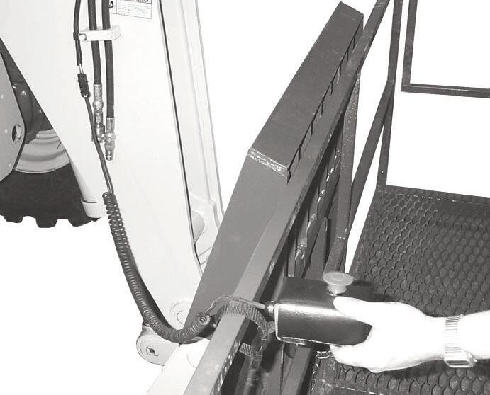
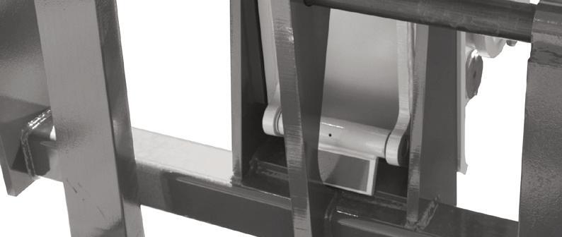
4. Tilt the Quick-attach System back so that the lock plate engages the attachment tool as shown below. This secures the attachment tool to the Quick-Attach system. Verify the attachment tool is properly secured by tilting the tool sufficiently forward such that it does not hinge away from the tool carrier.

Warning
Failure to verify that the attachment is securely attached to the Quick-attachÔ before working with the attachment could result in serious injury or death.
Attachment Tool Shown Locked to Quick-attach System
Quick-attach System Attaching Detail
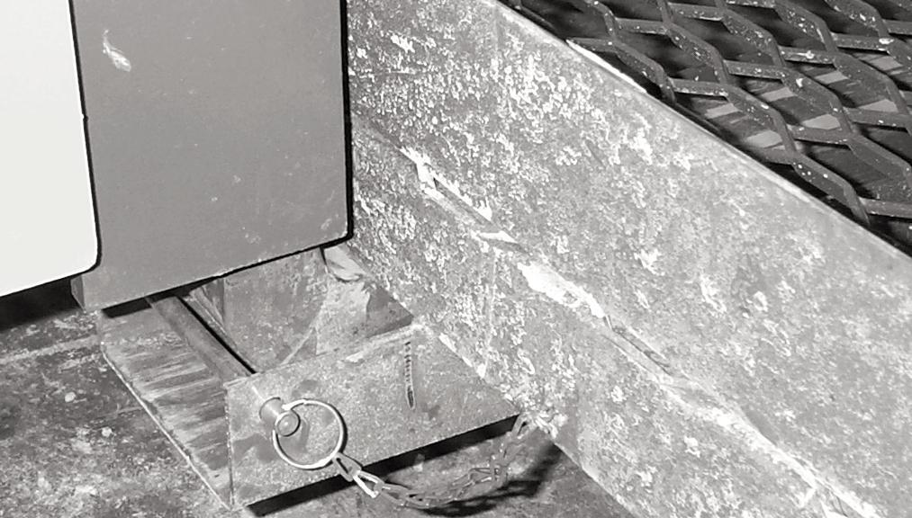
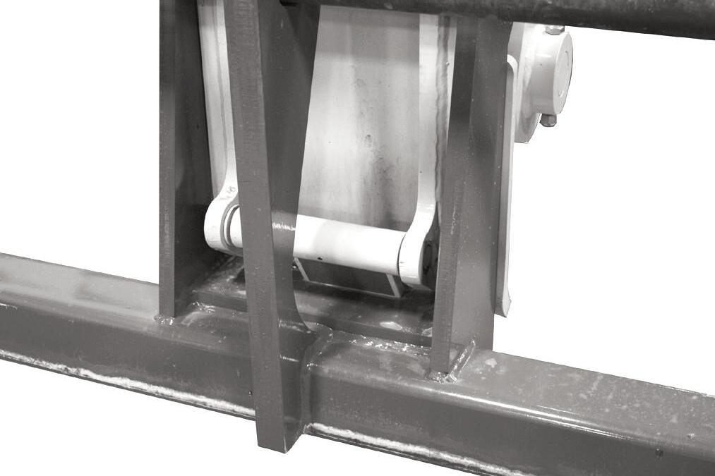
Attachment Tool Shown Unlocked for Release from Quick-attach System
Quick-attach System Detaching Detail
4. Tilt the Quick-attach System forward to allow the attachment tool to roll out, then lower the boom so the hook ears clear the hookup bar on the attachment tool.
NOTE: One side of the lock plate has a bright red decal to indicate the unlocked position.
5. If the attachment tool has auxiliary hydraulics, disconnect the hoses from the quick-disconnects on the boom nose.
6. Start the engine and tilt the Quick-attach System forward, then slowly back the machine until the attachment tool is free from the boom nose.
Warning
Modifications, alterations to, or use of attachment tools NOT authorized by Manitou Group (or the manufacturer) in writing can void warranty and cause machine damage and/or serious personal injury or death.
SELF-LEVELING
The machine is equipped with a hydraulic self-leveling feature. This feature is designed to keep the attachment tool level while the boom is being raised or lowered.
Machine Operation With Solid Rubber Tires
Solid rubber tires are designed for intermittent service and limited running distances. The Working Day Average Speed should not exceed 3 mph at an average load of 75% of maximum capacity. Telehandlers equipped with solid rubber tires should not be used in applications requiring speeds over 15 mph, or continuous journeys over 1 mile when loaded at or above 50% of capacity. In the event an application requires vehicle speeds over 15 mph, excessive roading, or driving extended distances while loaded, Manitou Group recommends the use of other approved tire options.
Warning
The RS9-50 telehandler must be equipped with foam filled or solid rubber tires for proper load capacity and stability.
Use of pneumatic tires will not provided published rated capacity or stability as shown on the load chart and may contribute to a tip over resulting in death, serious injury or property damage.
General Machine Operation
Take time to check the Telescopic Handler to be sure all systems are in good operating condition. Perform the following steps before starting the machine for the first time each day:
1. Check the engine oil, coolant, transmission oil and hydraulic oil levels.
2. Be sure weekly lubrication has been done.
3. Visually inspect for leaks, broken or malfunctioning parts. Be sure all caps, covers and safety shields are in place.
4. Check tires for cuts, bulges, nails, correct pressure, loose wheel nuts, etc.
5. Inspect the work area. Be sure you know where you will make load pickups, placements, lifts, and turns. Look over the terrain of the jobsite for holes, obstacles, slippery surfaces, and soft or deep mud.
6. Check clearances of ramps, doorways and passageways. Check overhead clearances if you will travel and place loads near power or telephone lines or other obstructions.
7. When traveling unloaded, tilt forks back and elevate boom as low as possible to obtain visability around the machine.
If the machine is found to be in need of repair or in any way unsafe, or contributes to an unsafe condition, the matter must be reported immediately to the user’s designated authority. The machine must NOT be operated until it has been restored to a safe operating condition.
Warning
Exhaust fumes can kill. Ensure proper ventilation when starting indoors or in enclosed areas.
Use proper handholds, NOT the steering wheel or control levers when mounting and dismounting.
NEVER operate the machine with safety guards or covers removed.
Over-inflated tires can explode and cause injury or death. Tire repairs MUST be made only by authorized personnel using proper tools and equipment.
Operate the travel controls gradually and smoothly when starting, stopping, turning and reversing direction.
Grade and Slope Precautions
The Telescopic Handler complies with industry stability test requirements and is stable when properly operated. However, improper operation, faulty maintenance, and poor housekeeping can contribute to a condition of instability.
The amount of forward and rearward tilt to be used is governed by the application. Although use of maximum rearward tilt is allowable under certain condi- tions, such as traveling with the load fully lowered, the stability of the machine, as determined by the industry standard tests, does not encompass consideration for excessive tilt at high elevations, or the handling of offcenter loads.
Only handle loads within the capacity limits of the machine, and which are stable and safely arranged. When attachments are used, extra care should be taken in securing, manipulating, positioning and transporting the load.
Grade Limits
NOTE: Grade limits are based on ANSI /ITSDF standard B56.6-2016.
This telescopic handler meets or exceeds the safety standard (ANSI/ITSDF B56.6 - 2016) stability limits for rough terrain forklifts. The stability tipping limits cover specific, controlled test conditions, which are extremes, and which are not intended to be achieved during normal worksite operations. The following specifications are provided only as information to the operator, and must not be used as a guideline for operating the Telescopic Handler. For safe operation, always follow the instructions and warnings provided in this manual.
Warning
DO NOT level the frame with the boom raised or extended. Only level the frame while stopped, and with the boom fully retracted and the attachment tool raised just enough to clear the ground.
1. DO NOT place or retrieve loads on an up or down slope or grade that exceeds 7% or 4°.
2. DO NOT travel up or down a grade or slope that exceeds 22% or 12° while loaded.
3. DO NOT place or retrieve loads on a side hill with a slope or grade that exceeds 12% or 7°. Regardless of terrain or position of wheels, the FRAME MUST BE LEVEL, as indicated by the level indicator on the ROPS/FOPS cross member.
4. DO NOT travel across a side hill that exceeds 18% or 10° grade. Regardless of the terrain or position of the wheels, the FRAME MUST BE LEVEL, as indicated by the level indicator on the
ROPS/FOPS cross member. The attachment tool MUST be maintained at the “carry” position with the boom fully retracted, and attachment tool at minimum ground clearance.
When ascending or descending grades in excess of 5% or 3°, the machine should be driven with the load upgrade. An unloaded machine should be operated on all forward grades with the load handling attachment tool downgrade, tilted back if applicable, and raised only as far as necessary to clear the road surface.
On grades, ramps and inclines, use extreme caution and avoid turning if possible. Normally travel straight up and down the slope.
Traffic Flow Patterns
Know and understand the traffic flow patterns of your jobsite. Know all Telescopic Handler hand signals for safety. Utilize signal persons and be sure you can see the signal person and acknowledge the signals given.


Safety Hand Signals


When ramps must be used in transporting loads with the machine, the following are the minimum widths for safe travel:
Compacted dirt, gravel, etc.3.6 m (12 ft.) Woodboard, concrete, etc.3.0 m (10 ft.)
Permanent aisles, roadways and passageways, floors and ramps must be clearly defined or marked. Permanent or temporary protrusion of loads, equipment, material and construction facilities into the usual operating area must be guarded, clearly and distinctively marked, or clearly visible.
Maintain a safe distance from the edge of ramps, platforms and other similar working surfaces.
Controlled lighting of adequate intensity should be provided in operating areas. Where operating conditions dictate, the operator/user is responsible for having the machine equipped with lights.
Provisions must be made to prevent trucks, semi-trailers and railroad cars from being moved during loading and unloading. Wheel stops, parking brakes, or other positive holding means must be used to prevent movement during loading and unloading.
DO NOT move railroad cars and trailers with the Telescopic Handler.

Do not use the travel drive and/or extend or retract the boom to push or pull a load or object.

DO NOT use the boom and attachment for leverage to push the machine out of mud.
IMPORTANT: DO NOT lower boom at high engine speed when attachment tool is at maximum rearward tilt. Damage to slave cylinders may result.

General Load Handling


NEVER operate controls except from the operator’s seat. NEVER jerk or use fast movements. Avoid sudden stops, starts and changes in direction.
Operation of the hydraulic system depends on engine speed and the distance the controls are moved. When operating these controls it is important to develop a technique called “feathering.” Feathering the control means starting the desired motion by moving the control a small distance away from neutral. Then after movement has started, the control can be eased to full travel. Use the same feathering technique to slow and stop the motion.
Warning
Excessive speed can be hazardous. ALWAYS exercise caution and good judgement while operating the machine.
ALWAYS maintain a safe distance from electric power lines and avoid contact with any electrically charged conductor and gas line. It is not necessary to make direct contact with a power line for power to ground through the structure of the machine. Keep the boom and load at least 3 m (10 ft.) from all power lines. Accidental contact with a power line or rupture of a gas line can result in electrocution or an explosion. Contact the “Call Before You Dig” referral system number at 8-1-1 in the U.S., or 888-258-0808 in the U.S. and Canada, to locate any underground utility lines BEFORE starting to dig.
Keep all body parts inside the operator’s station while operating the machine. BE SURE of clearance for the attachment tool when turning, working around buildings, etc.
Turning corners too fast can tip the machine, or cause a load to slide off the attachment. Sudden slowing or stopping of the machine may cause the load to drop off the attachment tool.
Be certain you can control both speed and direction before moving. Always place the machine in neutral and set the parking brake before raising or extending the boom. NEVER drive the machine up to someone standing in front of the load.
NEVER leave the operator’s station without first lowering the attachment tool to the ground. Then set the parking brake, place controls in neutral, shut off engine and remove the key. AVOID parking the machine on a slope, but if necessary, park across the slope and block the tires.
Load Capacity and Reach
This machine has flip-charts in the operator’s station that provide, at a glance, the load capacity limits at various positions of attachment tool extension and elevation. A set of the load zone charts is reproduced at the end of this manual for reference.
A typical load zone chart is shown on this page. The scale on the left indicates height in feet above the ground level. The scale on the bottom shows the distance in feet out from the front of the machine. The arc lines noted by the numbers “1” through “5” correspond with the boom extension marks on the operator side of the intermediate boom section.

The following example illustrates proper use of the load zone charts for the Telescopic Handler:
Typical Load Zone Chart
Example: The operator, using a standard carriage attachment tool without outriggers, wants to raise a 4000 lb. load 25 feet high, and can only get to within 15 feet of the load placement point. Can this be done within the capacity of the machine?
Analysis: See “Typical Load Zone Chart” above. Projecting up from the 15-foot reach mark on the horizontal axis to intersect a line through the 25-foot height mark on the vertical axis shows that a load up to 4000 lb. can be placed in that zone.
During placement, the operator should observe when the boom extension mark number “4” on the boom is visible and stop further extension. The operator knows the maximum safe extension distance with the 4000 lb. load has been reached.
Warning
NEVER exceed the rated operating capacity of the Telescopic Handler as shown on the load zone charts.
HANDLING NON-SUSPENDED LOADS
Picking Up the Load
Inspect the load. If it appears unstable, DO NOT attempt to move it. DO NOT attempt lifting doubletiered loads, or straddling side-by-side pallets with one on each fork. NEVER add extra unauthorized counterweights to this machine. Consider the additional weight of any attachment tool as part of the picking load capacity of the machine.
Warning
Operating conditions can reduce the machine’s safe operating capacity. Exceeding the capacity when raising or extending the boom will cause the machine to tip forward.

Approach the load slowly and squarely with the machine straight and level. Adjust the space between forks, if necessary. Engage the load equally on both forks until the load touches the carriage backrest. Tilt the forks back to position the load for travel.
Carrying the Load
If the load obstructs your view, get someone to direct you. Maintain ground speeds consistent with ground conditions and that permit stopping in a safe manner.
Load Elevation and Placement
For ground level load placement, be sure the area under the load and around the machine is clear of equipment and personnel. Lower the load to the ground, tilt the forks to the horizontal position, and then carefully back away to disengage the forks from the load.
For elevated or overhead placement, bring the machine as close as possible to the landing point, and then:
1. Level the machine BEFORE raising the load. Use extreme caution for high placement. Be sure personnel are clear of the area where the load or the machine could fall or tip.
2. Set the parking brake, shift the transmission into neutral, hold the service brake pedal fully applied and slowly raise the load, maintaining a slight rearward tilt to cradle the load.
3. As the load approaches the desired height, feather the boom control at minimum speed until the load is slightly higher than the landing point.
4. Continuing the feathering technique, lower the load into place.
5. Free the forks from the load by alternately retracting and raising the boom. If this process is not possible, very slowly and carefully reverse the telescopic handler to free the forks from the load.
6. Lower the forks to travel height.
Handling Suspended Loads
Determine the weight and apply proper rigging technique for the load being handled. Refer to the telehandler load chart to determine if the load can safely be handled.
An optional boom mounted hook is available for handling suspended loads. Contact your Manitou Group dealer.
Warning
NEVER travel with the boom above the carry position (attachment tool should be at minimum ground clearance). Boom should be fully retracted.
Use lower gear when traveling down an incline. NEVER coast with the transmission in neutral. Travel up and down grades slowly.
DO NOT operate the machine on a slope or grade that exceeds 22% or 12o
NOTE: Refer to the standard carriage load chart when using the boom mounted hook.
Warning
NEVER exceed the rated operating capacity of the telehandler as shown on the load zone charts.
Warning
Operating conditions can reduce the telehandler’s safe operating capacity. Exceeding the capacity when raising or extending the boom will cause the telehandler to tip forward.
Picking Up Suspended Load
1. Rigging should be in good condition and rated for the load being lifted.
2. Rigging should comply with OSHA regulation §1910.184, “Slings,” or §1926.251, “Rigging equipment for material handling.”
3. Be sure the rigging equipment is clear of any part of the machine or machine attachment before lifting the load.
4. Avoid lifting double-tiered or any unstable loads.
5. Only lift loads vertically and clear from any adjacent obstacles. Never drag the load horizontally.
6. Use multiple lift points and taglines to restrain the load from swinging or rotating.
Carrying Suspended Load
4. Use a signal person anytime the load restricts the operators view or assistance is required. The signal person should remain in contact (verbally or visually) with the operator at all times until the load is placed.
Ground Level Suspended Load Placement
1. Be sure the area under the load and around the telehandler is clear of equipment and personnel.
2. Lower the load to the ground till load is stationary and the rigging is loose from the load. Have signal person disconnect the rigging from the load.
3. Raise boom enough to clear the rigging from the load before backing the telehandler away from the load.
Elevated Suspended Load Placement
1. Bring the telehandler as close as possible to the landing point.
2. Level the telehandler BEFORE raising the load. Use extreme caution for high placement. Be sure personnel are clear of the load landing area.
3. Set the parking brake, shift the transmission into neutral, hold the service brake pedal fully applied and slowly raise the load.
4. As the load approaches the landing point, feather the boom control at minimum speed until the load is just above the landing point.
5. With the assistance of a signal person, continue the feathering technique to lower the load into place.
6. Once the load is stationary on the landing point and the rigging is loose from the load, have the signal person disconnect the rigging from the load.
Warning
NEVER place the signal person between the load and the telehandler or other stationary objects.
1. Rigging between the load and attachment should be as short as possible to reduce boom height.
2. Do not raise the load more than 305 mm (12 inches) above the ground or raise the boom more than 45 degrees.
3. All telehandler movements should be performed slowly and cautiously to prevent load swing. Avoid abrupt movement. Do not exceed walking speed.

7. Raise boom enough to clear the rigging from the load. Slowly and carefully, reverse the telehandler till the rigging is clear of the load.
8. Lower the boom to travel height.