9 minute read
Installation of a Personnel Work Platform (PWP)

from Gehl RS SERIES GEN:4 M74 RS6-42 RS8-42 RS8-44 RS9-50 RS10-44 RS10-55 RS12-42 Operator's Manual - PDF

Warning
The machine must not be used to lift or carry personnel, or be fitted with any form of personnel work platform unless fitted with the optional PWP System. If fitted with the PWP System, the Mandatory Work Platform Safety Rules (p. 22) must be followed to at all times while lifting personnel.
1. Center the forks on the carriage, spaced apart to match the distance required to engage the PWP.
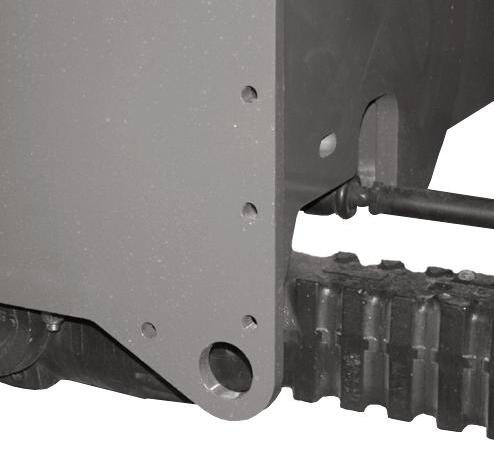
2. After the forks are fully engaged in the PWP, secure the PWP to the forks. This can be accomplished by means of a retaining pin behind the heel of the forks, as shown.
Warning

The PWP must meet ANSI/ITSDF B56.6-2016, Section 8.24. (See page 24 in the Safety chapter for PWP design requirements.) If the PWP being used does not offer means to secure the PWP to the forks and to secure the forks from pivoting, as shown in steps 2 and 3, then an alternate method must be used.
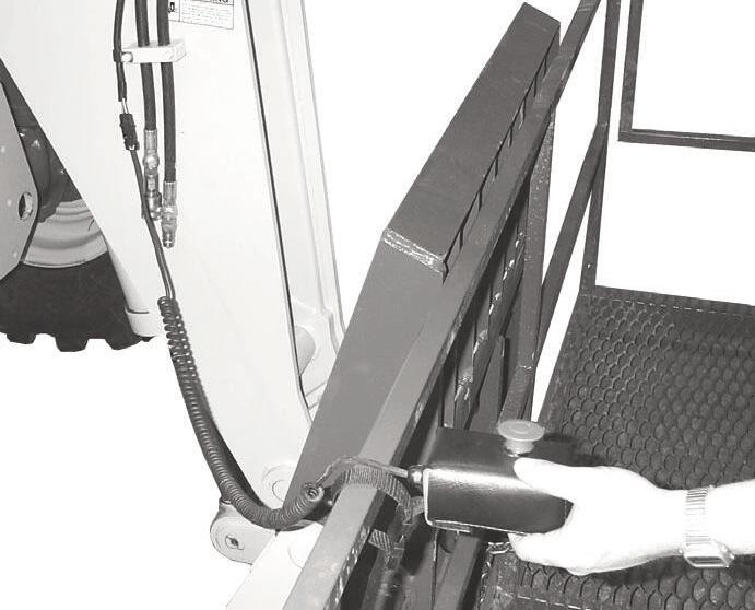
4. For machines with a 42-foot or 44-foot boom: Connect the coiled wire from the remote shutdown switch to the connector on the end of the boom. Secure the remote shutdown switch to the PWP using the strap attached to the switch, as shown.
Electrical Connection
PWP Remote Shutdown Switch
3. Secure the forks from pivoting upward in case the PWP is lowered onto an obstruction. This can be accomplished by using the chain supplied with the PWP, to secure the lower portion of the PWP to the bottom of the carriage, as shown below.

Remote Shutdown Switch with Coiled Wire Connector
5. For machines with a 50-foot or 55-foot boom: The remote shutdown switch is wireless-operated. Secure the remote shutdown switch to the PWP using the strap attached to the switch, as shown.


PWP Remote Shutdown Switch
Wireless Remote Shutdown Switch on 50’ and 55’ Models
6. Secure the lanyard from the body harness to the PWP or the boom. Each person in the PWP should have a body harness with a lanyard attached to the PWP.
Elevating Personnel
This Telescopic Handler is primarily intended for use as a material handler. It should only be used to elevate personnel if it is equipped with the (optional) PWP System when there is no other practical option. If this machine is to be used to elevate personnel, then use only an approved work platform, lift personnel only with the PWP System activated, and follow the “Mandatory Work Platform Safety Rules” (p. 22, Safety chapter).
If this Telescopic Handler is equipped with a PWP System and is to be used for elevating personnel, the system must be activated, by the "PWP System" mode switch, which is located in the instrument and switch panel. To activate the system, press the top of the PWP rocker switch, apply and hold the service brakes on for three or more seconds. The system is activated when the lamp in the PWP rocker switch is on continously.
NOTE: If the light is flashing, apply the service brakes until the light stops flashing.
Warning
ALWAYS check the PWP System for proper operation prior to use. (See page 79 for PWP System checking procedure.)
When the PWP System is active: l transmission is de-clutched into Neutral l parking brake is applied l rear axle stabilizer cylinder is locked l auxiliary hydraulic and carriage tilt and swing functions are disabled l machine inclination sensor is activated, with the result that the Telescopic Handler must be level laterally (side-to-side) and longitudinally (front-to-back) to within the factory preset limits before the boom control joystick will function l For 42-foot and 44-foot models, the remote shutdown switch is activated, with the result that the switch must be connected and in the “on” position for the boom control joystick to function. Depressing the switch will disengage the boom control joystick, and stop all platform movement. The remote shutdown switch box is supplied with a coiled electrical cable that must be connected to the outlet on the front of the innermost boom section near the carriage. The switch must be accessible by the platform personnel any time the platform is to be moved. l For 50-foot or 55-foot models, remote shutdown switch is activated, meaning that the switch must be “on” for the boom control joystick to function. Pressing the red button will disengage the boom control joystick and stop all platform movement. The remote shutdown switch box is a wireless remote control, so there is no direct connection to the Telescopic Handler. The switch must be accessible to the platform personnel at all times when the platform is to be moved.
To de-activate the system, apply and hold the service brakes on for three or more seconds, and press the bottom of the PWP System rocker switch. The system is de-activated when the lamp in the PWP System rocker switch is off.
NOTE: If the lamp in the PWP system rocker switch is flashing, apply the service brakes until the lamp goes off.
Warning
In an emergency, if the platform worker has activated the remote shut-off switch and then is not able to re-activate the switch, such as if the worker fainted, then the Telescopic Handler operator is permitted to turn off the PWP System to regain control of the boom functions, in order to lower the work platform and come to the aid of the worker. But, understand this is only permitted in case of an emergency. Otherwise, the PWP System must be used at all times when there are workers on the platform. This is the only exception!
Stabilizer System
This is an additional safety function while elevating loads for placement. At a pre-determined angle, the stabilizer cylinder on the rear axle will lock up. When this happens, the parking brake is activated. The machine will not be able to move until the boom is lowered below the pre-determined angle.
Warning
The machine becomes less stable as the load is raised higher.
NEVER use frame leveling to position an elevated load. Always lower the load to the ground and reposition the machine.
If a hydraulic boom circuit hose should break with the boom up, shut down the machine. DO NOT attempt to bring down the boom or make repairs. Call your Manitou Group dealer immediately.
As lift height increases, depth perception decreases. High elevation placement may require a signal person to guide the operator.
DO NOT ram the lift cylinders to the end of the stroke. The resulting jolt could spill the load.

A jib or truss boom should ONLY be used to lift and place loads when the machine is stationary and the frame is level. Transporting suspended loads must ALWAYS be done slowly and cautiously, with the boom and load as low as possible. Use taglines to restrict loads from swinging, to avoid overturn.
Road Travel
For short distance highway travel, attach a SlowMoving Vehicle (SMV) emblem (purchased locally) to the rear of the Telescopic Handler. For highway operation, obtain and install an amber flashing beacon.
NOTE: ALWAYS follow ALL state and local regulations regarding the operation of equipment on or across public highways. Whenever there is an appreciable distance between jobsites, or if driving on public highway is prohibited, transport the machine using a vehicle of appropriate size and capacity.
Transporting Between Jobsites
ALWAYS abide by the following recommended procedures and guidelines when using ramps to load the machine onto (and unload it from) a truck or trailer. Failure to heed can result in damage to equipment and serious personal injury or death!
Tie-down eyes are provided for inserting chains through to secure the machine during transport.
Loading Machine Using Ramps
NOTE: A matched pair of ramps is required.
1. The ramps MUST be of sufficient strength to support the machine. The use of strong steel ramps is recommended, as well as center supporting blocks.
2. The ramps MUST be firmly attached to the truck or trailer bed with NO step between the bed and the ramps.
3. The incline of the ramps MUST be less than 15 degrees. For a four-foot high truck bed, ramp length must be at least 4.9 m (16 feet) long.

4. Ramp width MUST be at least 1-1/2 times the tire width.
5. Block the front and rear of the tires on the truck or trailer. Engage the parking brake.
6. Position the machine with the boom facing toward the front of the truck or trailer so that it is straight in line with the ramps.
7. Slowly (at the lowest engine speed possible) and carefully drive the machine up the ramps.
8. Secure the machine to the bed of the truck or trailer with tie-down chains/cables.
Warning
NEVER adjust travel direction (even slightly) while on the ramps. Instead, back off the ramps, and then realign the machine with the ramps.
Warning
NEVER transport the machine with the boom raised or extended. BE SURE to secure the machine (including boom) to the truck or trailer bed using chain and binders or steel cables, to prevent any movement while transporting.
Unloading Machine Using Ramps
NOTE: A matched pair of ramps is required. Repeat steps 1 through 5 and proceed as follows to unload the machine:
6. Remove the tie-down chains/cables.
7. If necessary, adjust the machine so that the wheels are in line and centered with the ramps.
8. Slowly (at the lowest engine speed possible) and carefully drive the machine down the ramps.
REAR CAMERA and REVERSE RADAR SYSTEMS (Optional)
These optional systems are available on the RS Series telehandler to aid operators in the operation of the telehandler.
Warning
The rear camera and reverse radar systems are offered as an option and are not required for machine operation. The Manitou Group RS Series telehandler features frame designs with through-frame operator sight lines to the rear of the machine. These optional systems are offered as a supplement to aid operators. However, operators remain responsible for checking the travel path for obstructions or hazards before moving the telehandler in that path
Rear Camera System
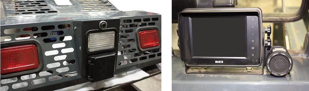
The rear camera system consists of the camera (1) and the viewing monitor (2).
The rear camera system provides a view of the area directly behind the machine.
Warning
Always use mirrors and look to the rear of the machine before and during backing. Clear any people or obstruction from your path before backing. Rear camera and reverse radar systems are for supplementary use only.
The rear camera system is activated any time the machine is running or the ignition key is in the "ON" position.
NOTE: The travel selector switch does not need to be in "REVERSE" for the camera to be activated.
The camera image is displayed on the monitor located on the right side of the dash.
To adjust the monitor vertical viewing angle, loosen the four knobs located on both side of the monitor. Tighten the four knobs after the monitor vertical viewing angle is adjusted. Prior to operating the machine, the operator should check the monitor to verify that the monitor is positioned at the optimum viewing angle for them.
IMPORTANT: Always keep the camera lens and monitor viewing surface clean for a bright and clear image.
Reverse Radar System
The reverse radar system is an optional addition to the rear camera system. It consists of the preview sentry (3) mounted at the rear of the machine, and the radar display (4) mounted on the right side of the viewing monitor (2).
Reverse Radar Operation
The reverse radar system provides an audible and visual indication of objects to the rear of the machine.
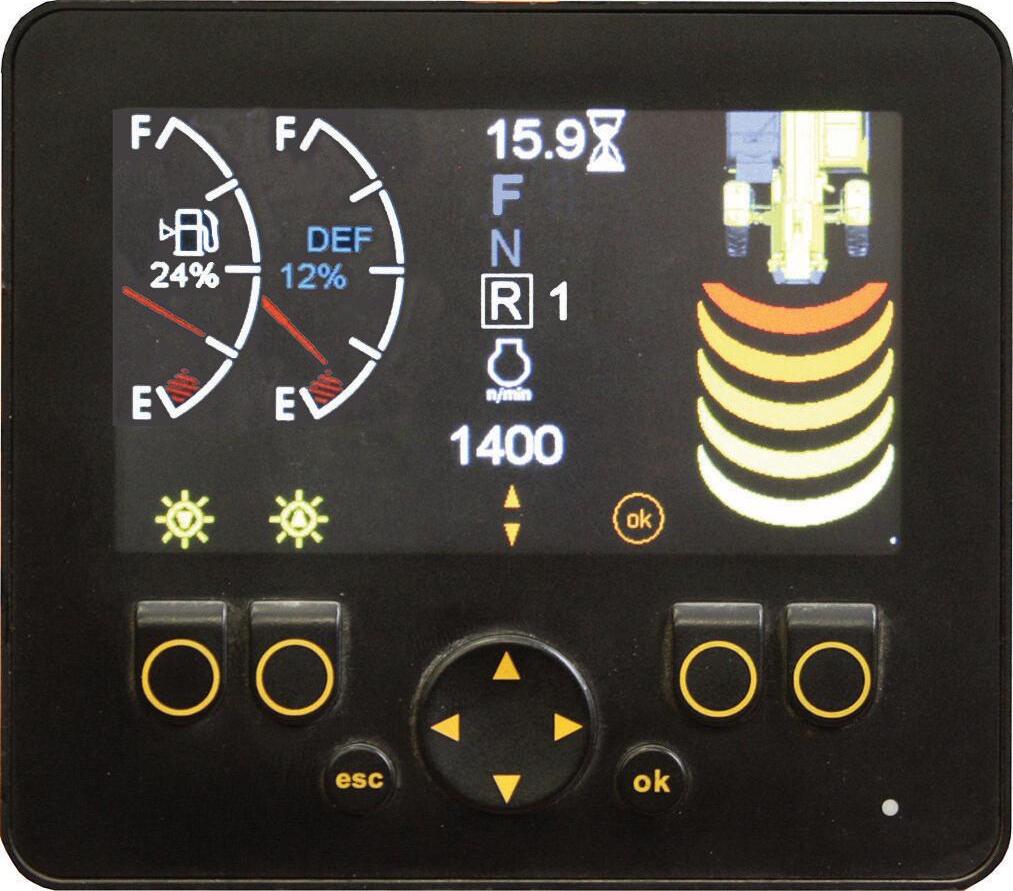
When the engine is running or the ignition key is in the "ON" position and the travel selector is in the reverse position, the following will occur: l The reverse radar system will activate. l If an object is detected within the reverse radar system coverage area the audible alarm will sound. l A visual indicator will appear in the right side of the multi-function display. l If 5 bars are shown in the display, the detected object is less than 4.57m (15') behind the machine. l The closer the obstruction is to the rear of the machine, the more bars will show in the multifunction display and the audible alarm will sound more frequently. l The operator should take steps to avoid the object, or perform the "Mandatory Safety Shutdown Procedure" and clear the obstruction from the travel path before proceding.
IMPORTANT: The reverse radar system covers an area 4.57m (15') back and 3.05m (10') wide to the rear of the machine.
NOTE: Each bar shown on the multi-function display represents .91m (3') from the back of the machine. For example, if 3 bars are shown, the object is less than 2.75m (9') behind the machine. If zero bars are shown, the reverse radar coverage area is clear of obstructions.
Theft Deterrents
Manitou Group has recorded all component part numbers and serial numbers. Users should take as many of the following actions as possible to discourage theft, to aid in the recovery of the machine in the event it is stolen, and to reduce vandalism:
1. Remove keys from unattended machines.
2. Attach, secure, and lock all anti-vandalism and anti-theft devices on the machine.
3. Lock doors of cabs when not in use.
4. Inspect the gates and fences of the equipment storage yard. If possible, keep machines in welllighted areas. Ask the local law enforcement agency to make frequent checks around the storage and work sites, especially at night, during weekends, and on holidays.
5. Report any theft to your dealer and insurance company. Provide the model and all serial numbers. Request your dealer to forward this information to Manitou Group.