3 minute read
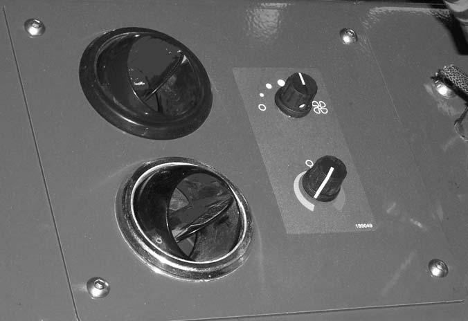
Heater A/C Controls


Fan Speed: This is the upper knob located to the left of the steering wheel. The fan is in the off position when the knob is rotated completely to the left. Rotating the knob clockwise will switch the fan on and increase the fan speed for increased air circulation.
Temperature Control: This knob is located below the fan speed knob. It is used to adjust the temperature output of the heater A/C unit. Turning the knob clockwise from the midpoint position will increase the temperature output of the cab heater. Turning the knob counterclockwise from the midpoint position will switch the A/C unit on and decrease the temperature output of the cab A/C.
Travel Lever
Located on the left side of the steering wheel column, this lever is used to change travel direction (forward or reverse) and speed.
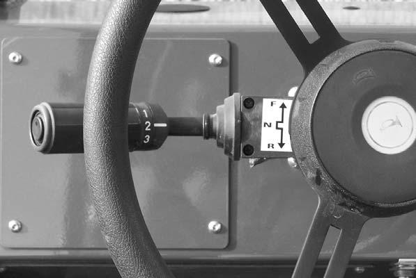
Position “F” (Forward)
Position “N” (Neutral)
Position “R” (Reverse)
Speed Range: Twisting the lever end clockwise or counter-clockwise will change the transmission speed between low, medium and travel ranges.
Position “3” (Travel Range)
Position “2” (Medium Range)
Position “1” (Low Range)
IMPORTANT: Care should be taken when downshifting or changing direction, because damage to the transmission can occur if shifting is forced or attempted at too high a speed. Allow engine speed to slow before any downshift or directional change is attempted.
Steering
Turn the steering wheel to the right or left to turn the machine in that direction.The power steering system is designed to provide low-effort steering without shock reaction from the tires to the steering wheel.
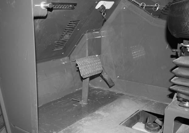
Floor And Seat Area
Throttle Pedal: This pedal, operated by the right foot, controls the engine speed to match power requirements. Pushing down on the pedal increases engine speed; letting up on the pedal decreases engine speed.
Service Brake Pedal: Pressing this pedal activates inboard hydraulic wet-disc-type brakes on all four wheels. Separate front and rear brake systems allow bringing the machine to a safe stop if either system loses pressure.
Travel Direction: The lever MUST be in “N” (Neutral) position before the starter will engage to start the engine.
NOTE: Backup alarm automatically sounds with travel lever in “R” (Reverse).
Brake Fluid Reservoir: Located under the hinged cover on the cab floor directly in front of the seat.
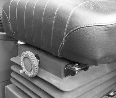
Seat Positioning: The seat is mounted on rails for forward and rearward repositioning, for comfort and to accommodate the operator’s size. A spring-loaded latch handle under the front of the seat actuates the adjustment mechanism.
Warning
Use extreme caution when raising or extending the boom. The Telescopic Handler MUST be level. Loaded or empty, the machine can tip over if it is not level.
ALWAYS place the transmission in neutral, apply the parking brake and keep the service brakes fully applied before raising or extending the boom.
NEVER exceed the specified lift and reach capacities of the machine, or serious machine damage and personal injury may result. Refer to the load charts at the operator’s station or this manual.
Suspension Seat Option: This option is available for additional operator comfort. It is adjustable for a soft or firm ride.

If a boom circuit hose fails with the boom up, with or without a load, shut down the machine following the MANDATORY SAFETY SHUTDOWN PROCEDURE. DO NOT attempt repairs. Instead, call your Gehl dealer for assistance.
The truss boom and winch attachment tools should ONLY be used to lift and place loads when the machine is in a stationary position. Transporting suspended loads must ALWAYS be done slowly and cautiously, with the boom and load as low as possible. Use taglines to restrict loads from swinging, to avoid overturn.
Seat Belt: This machine has a retractable seat belt. Grasp the belt on the left side of the seat, pull the belt over your lap, and insert the belt into the buckle on the right side of the seat until you hear it lock in place.
NEVER use winch for lifting or moving personnel. NEVER exceed the maximum rated capacity of the winch (3000 lbs./1360 kg) or exceed the load chart rating for winch applications.
DO NOT tilt the truss boom back more than 45o from horizontal. DO NOT attempt to use the optional rotating carriage as a load leveling function. ALWAYS level the frame prior to raising a load.
Failure to heed could result in death or serious injury.
Right Side Panel

Joystick Controls: These controls and indicators are used to position the frame, boom and attachment. Graphic symbols on the side panel indicate the control actions and effect.
This machine is equipped with one of two types of boom and attachment joystick control configurations, either a two-joystick configuration, or a single tri-function joystick.


