8 minute read
SAFETY


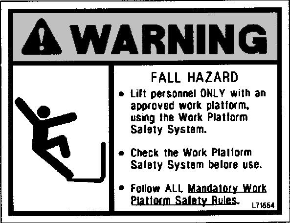
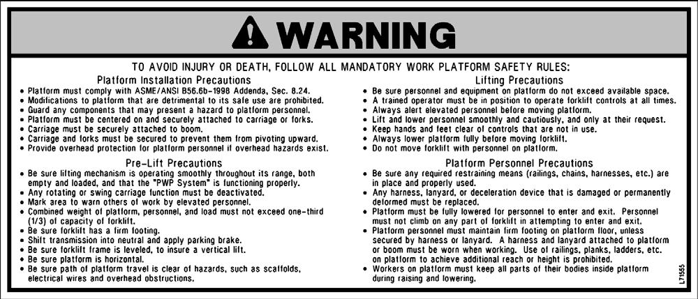
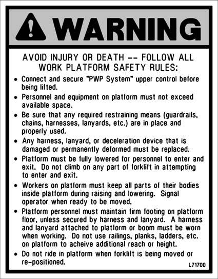
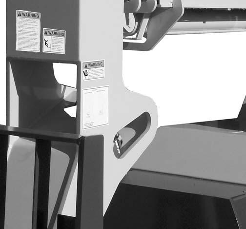
PWP Safety Decals


Chapter 5
Indicators And Controls
Guards And Shields
Caution
Become familiar with and know how to use ALL safety devices and controls on the Telescopic Handler BEFORE operating it. Know how to stop the machine operation BEFORE operating it. This Gehl machine is designed and intended to be used ONLY with a Gehl Company attachment tool, or a Gehl Company approved accessory or referral attachment tool. Gehl Company cannot be responsible for product safety if the machine is used with a non-approved accessory or attachment tool.
Whenever possible and without affecting machine operation, guards and shields are used to protect potentially hazardous areas. In many places, decals are also provided to warn of potential hazards and to display special operating procedures.
Warning
Read and thoroughly understand all safety decals on the Telescopic Handler BEFORE operating it. DO NOT operate the machine unless all factory-installed guards and shields are properly secured in place.
Boom Angle Indicator
Frame Angle Indicator
Frame Level and Attachment Joystick
Speed and Travel Direction Lever
Steering Wheel
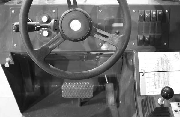
Brake Pedal
Instrument and Switch Panel
Boom Control Joystick
Auxiliary Hydraulics Control
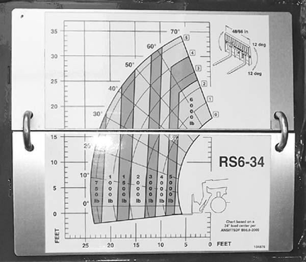
Load Zone Charts
Two Joystick Controls
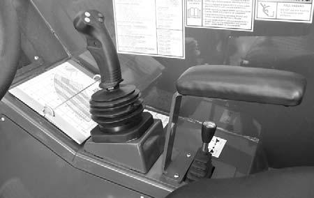
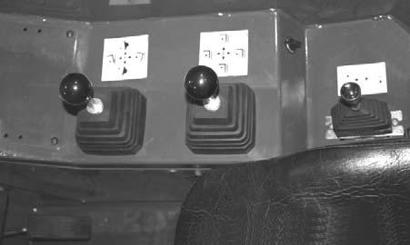
Tri-Function Joystick
Frame Level Control
Ignition Switch
Throttle Pedal
Tri-Function Joystick Control
Operator’s Compartment and Indicators/Controls Locations
Ignition Switch
Key Switch OFF: When the key is vertical in the ignition switch, power is disconnected from the battery to the control and instrument panel electrical circuits. This is the only position in which the key can be inserted and removed.
Key Switch ON: When the key is turned one position clockwise from the vertical (OFF) position, power from the battery is supplied to all controls and multi-function display panel electrical circuits. All indicators lamps in the multi-function display will illuminate momentarily as a lamp check.

When the key is in this position, the engine glow plug indicator will stay on until the engine is pre-heated. In colder temperatures the glow plug indicator will stay lit for 3-30 seconds. When the glow plug indicator light goes out the engine can be started.
Start: Turn the ignition switch to this position to activate the starter. Release the ignition switch as soon as the engine starts.
NOTE: If the engine requires repeated attempts to start, the key MUST be returned to the OFF position between starting attempts to prevent battery run down.
Warning
Do not use starting fluid (ether) with engine glow plug preheat systems. An explosion can result, which can cause engine damage, injury or death.
Horn: Located in the center of the steering wheel, press the horn button to activate warning sound.
Load Zone Charts: A series of flip charts show lift height and reach limits relative to the load weight being handled with various attachment tools.
Instrumentation and Switch Panel

Located to the right of the steering wheel, this panel contains the multi-function display with indicator lamps and the function rocker switches.
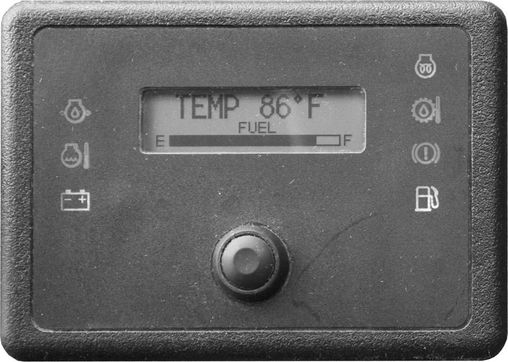
Multi-Function Display with Indicator Lamps
A - Multi-Function Display Screen: This screen displays the following functions:
• fuel level displayed at all times on the lower portion of the display,
• engine coolant temperature,
• engine oil pressure,
• voltmeter
• hourmeter
• 250 hour maintenance reminder
• air filter restriction message
• error fault codes
B - Scroll Button: Pressing this button changes the function displayed in the gauge display panel.
A1 - Fuel Level Gauge: The fuel level is displayed at all times in the lower portion of the display. It indicates the amount of fuel remaining in the fuel tank.
A2 - Engine Coolant Temperature: Press button “B” until “TEMP” is displayed. It indicates the temperature of the engine coolant. Under normal conditions, this should indicate approximately 185°F (85°C).
A3 - Engine Oil Pressure: Press button “B” until “OIL” is displayed. This indicates the engine lubricating oil pressure.
A4 - Voltmeter: Press button “B” until “VOLTS” is displayed. This indicates the voltage output from the alternator.
A5 - Hourmeter: Press button “B” until “HRS” is displayed. It indicates the total operating time of the machine and should be used for keeping the maintenance log.
A6 - Maintenance Reminder: After every 250 hours a reminder will display: “ROUTINE MAINTENACE IS REQUIRED ⎯ CHECK OPERATOR’S MANUAL.” Perform the required maintenance, and then clear the message by pressing and holding button “B” until the message is cleared.
NOTE: The maintenance reminder message must display at least three minutes before it can be cleared by pressing and holding button “B”.
A7 - Air Filter Restriction: This message will appear anytime the air cleaner is restricted. Check the air cleaner for a clogged element and replace if neccessary. The message will clear when the air cleaner restriction is corrected.
A8 - Error Fault Code: Error codes and a short error description are displayed in this screen. The error code will clear when the error is corrected.
Indicator Lamps
C - Low Fuel Lamp: This lamp indicates a low fuel situation. The fuel tank should be filled as soon as possible.
D - Brake Failure Lamp: This lamp indicates the condition of the service brake systems. The front and rear brakes are on independent systems. If a loss of pressure occurs in either system during normal operation with the brake pedal depressed, this lamp will come on. Failure in one of the brake systems does not affect the operation of the other system. However, the MANDATORY SAFETY SHUTDOWN PROCEDURE (p. 11) should be followed and any necessary repairs made immediately.
E - Transmission Oil Temperature Lamp: This lamp indicates whether or not the transmission oil is at the proper temperature. During normal operation this lamp should be off, indicating that the transmission oil system is at the proper temperature.
IMPORTANT: If this lamp comes on during normal operation, a problem may exist in the transmission oil system. Stop the machine immediately and investigate the cause of the problem!
F - Engine Glow Plug Indicator Lamp: When lighted this lamp indicates that the glow plug cold weather starting aid is in use.
G - Alternator Lamp: This lamp indicates the condition of the electrical charging system. During normal operation, this lamp should be off. If the charge rate is too high or too low, this lamp will come on.
H - Coolant Temperature Lamp: This lamp indicates if the temperature of the engine coolant is too high.
IMPORTANT: If this lamp comes on during normal operation with the engine running, STOP the engine as soon as possible and check the engine cooling system.
I - Engine Oil Pressure Lamp: This lamp indicates whether the engine lubricating oil pressure is sufficient. During normal operation, with the engine running, this lamp should be off. During starting and when the ignition is on but the engine is not running, this lamp will be on.
IMPORTANT: If this lamp comes on during normal operation, stop the engine immediately! After allowing the oil to drain down for a few minutes, check the engine oil level. Maintain oil level at the FULL mark on the dipstick.
Switch Panel
The switch panel contains three rows of switches for the operation of standard and optional equipment on the telescopic handler.
Top Row Switches
Switches have graphic symbols to indicate function and effect. The following descriptions start with the first switch on the left.
C - Engine Emergency Override Switch: Pressing and holding the bottom of the engine emergency override switch will override an ECU engine shutdown signal.
The switch must be pressed within 30 seconds of the engine shutdown signal from the ECU to prevent undesired shutdown of the engine. Pressing the switch will override the engine shutdown for 30 seconds at a time to move the machine to a safe location and to lower the boom to the ground. If the engine shuts down, the ignition switch must be turned off for 30 seconds and then back on before the engine can be restarted.
NOTE: Holding the switch continously “ON” will not reset the 30-second timer.
Refer to the error fault code displayed in the multifunction display to determine the cause of the engine shutdown signal.
NOTE: Some switches are optional and may not be on machine.
A - Steering Mode: This 3-position switch is used to select among the three steering modes. The upper position engages the 4-wheel-steer mode. This mode provides all-wheel steering, used for making tighter turns, usually on a jobsite. The center position engages the 2wheel-steer mode. This mode provides front-wheel steering only, used for higher speed travel. The lower position engages the crab-steer mode. This mode is used when a small amount of side shift is needed for picking or placing a load.
NOTE: The rear wheels are not self-centering. Make sure all wheels are in a straight-ahead position before changing the steering mode.
Any of the steering modes can be used in forward and reverse travel. The operator should learn to anticipate changes in machine movement if the steering mode must be changed.
B - Clutch Cutout: When activated, this switch allows faster engine acceleration and more power to the hydraulic system, without power to the drive axles, while the service brake pedal is pressed.
In the “OFF” position, the clutch mechanism of the transmission remains engaged when the brakes are applied. In the “ON” position, the clutch mechanism is disengaged when the brakes are applied.
Normal brake force will hold the machine in position while accelerating the engine to power hydraulic control functions during load placement.
D - Parking Brake: When the machine is parked, this switch should be pressed to actuate the parking brake mechanism in the front axle.
Warning
Unattended Machine Hazard
Activate parking brake switch and lower attachment tool to ground before leaving machine. An unattended machine can move or roll and cause death or serious injury to operator or bystanders.
Periodically check the parking brake operation to maintain adequate holding power. Always be sure the parking brake switch is off when resuming machine operation.
Middle Row Switches
Switches have graphic symbols to indicate function and effect. The following descriptions start with the first switch on the left.
NOTE: Some switches are optional and may not be on machine.
I1 and I2 - Wiper/Washer: The windshield and top window of the operator’s station are each equipped with a wiper and washer mechanism. Switch “I1”operates the wiper and washer on the windshield; switch “I2” operates the wiper and washer on the top window.
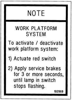
J - Personnel Work Platform: This is a red switch used to activate the Personnel Work Platform (PWP) System. When activated, an amber lamp in the switch will be on.
NOTE: Some switches are optional and may not be on machine.
E - Head Lights/Work Lights: Pressing the top of the switch will illuminate the lights mounted on the top of the operator’s station and the red tail lights, for use in forward travel operations. Pressing the bottom of the switch will illuminate the lights at the end of the boom in addition to the lights on the operator’s station, for additional lighting in working operations.
F - Turn Signal: This switch is used to indicate the direction of a turn with the tail lights. Depress the right arrow for a right turn; depress the left arrow for a left turn. Return the switch to the center position after the turn is completed.
G - Hazard: This switch can be activated to make the tail lights flash on and off in case the machine is stalled or temporarily stopped in a traffic area on the road or jobsite.
H - Strobe Light: When a stobe light is installed on the machine, activating this switch will produce a strobe light on and off flashing, for working in conditions that may obscure view of the machine.
Bottom Row Switches
Switches have graphic symbols to indicate function and effect. The following descriptions start with the first switch on the left.
NOTE: This lamp will flash on and off, indicating that the system is not yet fully functional, until the brakes are held on for three or more seconds.
K - Blank:
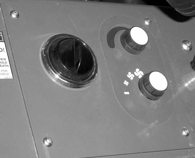
Heater Controls
Temperature Control: This is the upper knob located to the left of the steering wheel. This knob is used to adjust the temperature output of the heater. Turning the knob clockwise will increase the temperature output of the cab heater.
Fan Speed: This knob is located below the temperature control knob. Rotating the knob clockwise will increase the fan speed for increased air circulation.