6 minute read
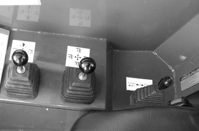
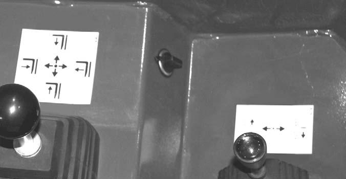
Two-Joystick Configuration


Auxiliary Hydraulics Control: This two-position lever is for attachment tools that require additional hydraulics.
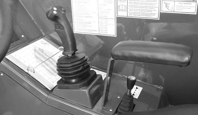
Tri-Function Joystick Configuration
Frame Level/Attachment Tilt Joystick: The machine may be tilted slowly as much as 10°to the left or right to level the frame and boom in relation to the ground. Move the joystick handle to the left to tilt to the left; move the joystick handle to the right to tilt to the right.
Warning
DO NOT level the frame with the boom raised or extended. Level the frame ONLY while stopped, with the boom fully retracted and the attachment raised just enough to clear the ground.
To tilt the attachment tool up, move the joystick handle rearward. To tilt the attachment tool down, move the joystick handle forward.
After the operator tilts the attachment tool to a desired angle, that angle will be maintained as the boom is raised and lowered, extended and retracted, until a new angle is set.
Boom Control Joystick: This machine has a hydraulic-type boom with telescopic sections. The sections extend by means of a hydraulic cylinder and chain system inside the boom, sequenced for uniform extension of each section.
To extend the boom, move the joystick handle to the right; to retract the boom, move the joystick handle to the left. To raise the boom, move the joystick handle rearward; to lower the boom, move the joystick handle forward.
Tri-Function Joystick: This joystick handle is equipped with two yellow buttons and two blue buttons on the upper rear of the handle, and a trigger switch on the front of the handle. The yellow buttons operate the attachment tilt. The blue buttons operate the auxiliary hydraulics. The trigger switch increases the function speed of both the attachment tilt and auxiliary hydraulics.
To extend the boom, move the joystick to the right; to retract the boom, move the joystick to the left. To raise the boom, move the joystick rearward; to lower the boom, move the joystick forward.
To tilt the attachment tool up, depress and hold the lower yellow button on the left side of the joystick handle; to tilt the attachment tool down, depress and hold the upper yellow button on the left side of the joystick handle.
To operate the auxiliary attachment hydraulics, depress and hold either the upper or lower blue button on the right side of the joystick handle. The upper blue button will cause the reverse effect of the lower blue button.
Depressing and holding the trigger on the front side of the joystick handle will increase the speed of the attachment tilt and auxiliary hydraulic functions.
NOTE: The joystick handle does not need to be moved to operate the tilt or auxiliary hydraulic functions.
Speed Control Knobs: The tri-function joystick incorporates a manually adjusted speed control. Speed adjustment is accomplished through the manual adjustment of pilot-pressure apply valves located next to the main valve at the rear of the machine.
NOTE: There is a locking knob located forward of the adjusting knob, which must be loosened before the adjusting knob can be turned. After adjustment has been made, tighten the locking knob to maintain the selected speed.
Frame Level Control: This control is located to the rear of the tri-function joystick. The machine may be tilted slowly as much as 10° to the left or right to level the frame and boom in relation to the ground.
Warning
DO NOT level the frame with the boom raised or extended. Level the frame ONLY while stopped, with the boom fully retracted and the attachment raised just enough to clear the ground.
12 Volt Accessory Power Port: Use this power port to power small electrical devices.
If the machine is equipped with auxiliary hydraulics, there will be two pilot-pressure apply valves, each having two speed-control knobs. The top pilot valve controls the auxiliary hydraulics, and the lower pilot valve controls the attachment tilt function. On the attachment tilt pilot valve, the left knob controls the attachment tilt-back speed, and the right knob controls the attachment tilt-forward speed. On the auxiliary hydraulic pilot valve, the function of the knobs will depend on the type of attachment requiring auxiliary hydraulics.
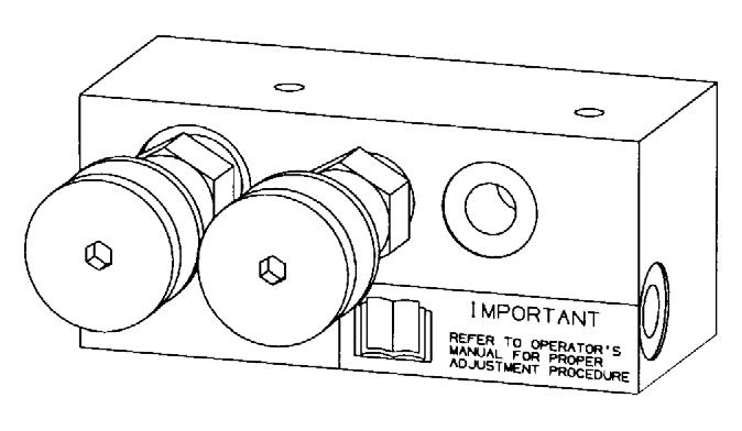
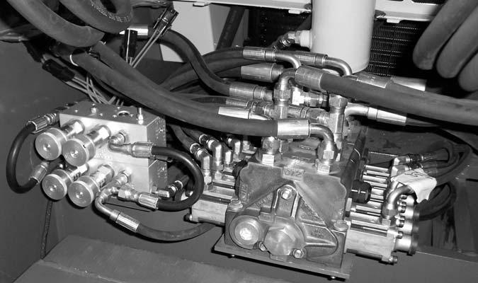
Turning a knob clockwise will increase the speed of its associated function. Turning a knob counter-clockwise will decrease the speed of its associated function.
Function Indicators
Frame Angle Indicator: Located in front of the operator on the ROPS upper cross tube, the position of the ball indicates when the frame is level relative to a sloping ground surface.
Angle Indicator
Boom Angle Indicator: Mounted on the left side of the outer boom, the movement of a ball indicates the angle of boom elevation relative to the ground.
Angle Indicator
Service And Safety Features
Coolant Level: Visually check the level of the engine coolant through the sight gauge located on the back of the radiator as shown. Remove the radiator cap to add coolant.
Radiator Cap
Coolant Level
Sight Gauge
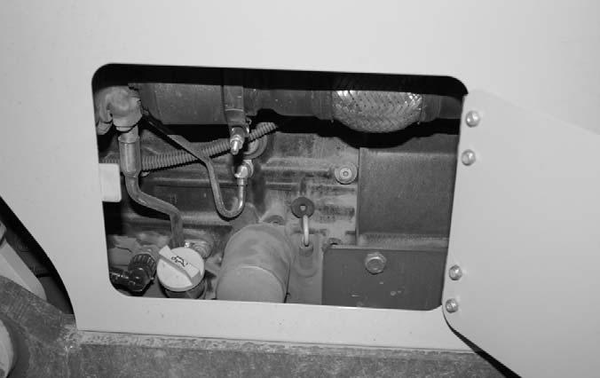
Engine Oil Level: The dipstick is located on the right side of the engine. Open the door to gain access to the engine oil dipstick, filter and filler.
Engine Oil Filter
Engine Oil
Hydraulic Pressure Test Ports: A gauge can be attached to these ports to check main valve, joystick and steering pressures.

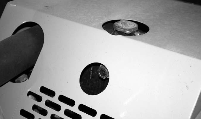
Transmission Oil Level: The dipstick is located under the access cover on the front hood section.

Battery Compartment: The battery is located under the access cover on the front hood section.

Backup Alarm: Located inside the rear frame cover, this alarm produces a loud warning sound when the machine is in reverse.
Backup Alarm
Side-View Mirror: Located on the front outside corner of the fuel tank, this mirror provides the operator with a view toward the rear of the machine.
Hydraulic Reservoir Oil Level and Fill Cap: The dipstick on the fill cap of the reservoir indicates the level of the hydraulic oil in the reservoir.
Side-View Mirror
Hydraulic
Air Filter Restriction: This message will appear in the multi-function display anytime the air cleaner is restricted. Check the air cleaner for a clogged element and replace if neccessary. The message will clear when the air cleaner restriction is corrected.
Fuse and Relay Access Compartment: This compartment is located under the load chart panel. Remove the four screws to gain access to the fuses and relays.

Fuses and Relays Functions: Remove the covers to access the fuses and relays.Refer to the illustration and following description for the fuse and relay functions.
Attachment Tools
Gehl Company offers a range of attachment tools to meet various lifting and material-handling applications. Contact your Gehl dealer for specifications and ordering information.
Accessories
Gehl also offers a range of special accessories for this machine. Contact your Gehl dealer for specifications and ordering information.
NOTE: All accessories are field-installed unless otherwise noted. Information and parts for installing accessories are provided by your Gehl Telescopic Handler dealer or Gehl Company.
FUSES:

1.15 AMP fuse: Ignition Switch, Horn, Brake Lights, and Clutch Cutout.
2.20 AMP fuse: Transmission, Park Brake, PWP, Steer Select, and Backup Alarm.
3.15 AMP fuse: Lights.
4.25 AMP fuse: Heater and Display.
5.25 AMP fuse: Top Wiper Motor.
6.25 AMP fuse: Front Wiper Motor.
RELAYS:
A.40 AMP change-over relay: Ignition.
B.40 AMP change-over relay: Ignition.
C.20 AMP relay: Front Wiper.
D.20 AMP relay: Park Brake.
E.20 AMP relay: Lights.
F.20 AMP relay: Top Wiper.
Chapter 6
Operation And Adjustments
General Information
Caution
BEFORE starting the engine and operating the Telescopic Handler, review and comply with ALL safety recommendations in the SAFETY chapter of this manual. Know how to STOP the machine before starting it. Also, BE SURE to fasten and properly adjust the seatbelt.
ENGINE BREAK-IN
A new engine does not require extensive “break-in.” However, for the first 100 hours of operation:
• Allow the engine to idle for a few minutes after every cold start.
• DO NOT idle the engine for long periods of time.
• DO NOT operate the engine at maximum power for long periods of time.
• Vary the engine speed and load.
• Check the oil level frequently, and replenish as necessary with the oil specified in the engine manual.
After the first 100 hours of operation, change the oil and replace the oil filter. Consult the Lubrication chapter or the engine manual for the type of oil to use in the engine. Refer to the Service and Storage chapter for the proper service intervals.
PRE-START WALK-AROUND INSPECTION
It is the operator’s responsibility to perform a pre-start inspect of the machine before the start of each workday. Every pre-start inspection must include more than simply checking the fuel and oil levels. It is a good practice to personally inspect any machine you are assigned to use, even though it has already been put into service by other personnel.
The pre-start inspection is designed to discover if the machine has incurred any damage or is in need of routine service.
Any needed repairs are to be made by a qualified service technician.
Refer to the illustration and checklist on the next two pages for the “Pre-Start Walk-Around Inspection.”


