4 minute read
Engine Diagnostic Chart (DPF Models) (end)


Hydraulic System
Checking Hydraulic Oil Level
The loader has a dipstick located in the engine compartment. Check the fluid level with the lift arm lowered and the attachment on the ground.
When hydraulic fluid is required, allow the system to cool. Slowly remove the oil fill cap, allowing the pressure to dispel before removing the cap completely. Add hydraulic fluid as required. Refer to the Lubrication topic (page65) for oil recommendations. Replace the cap.
Changing Hydraulic Oil Filter
Before servicing the hydraulic filter, be sure the lift arm is lowered.
1.Open the rear door and engine cover to access the filter. Unscrew the filter.
2. Clean the surface of the filter housing where the element seal contacts the housing. Put clean oil on the rubber gasket of the new filter element.
3. Install and tighten the filter element 3/4 of a turn past the point where the gasket contacts the filter head.
4. For a replacement element, refer to the Replacement Parts topic (page63).
Changing Hydraulic Oil
The hydraulic oil must be replaced if it becomes contaminated, after major repairs, and after 1000 hours or one year of use.
1.Remove the oil filler cap.
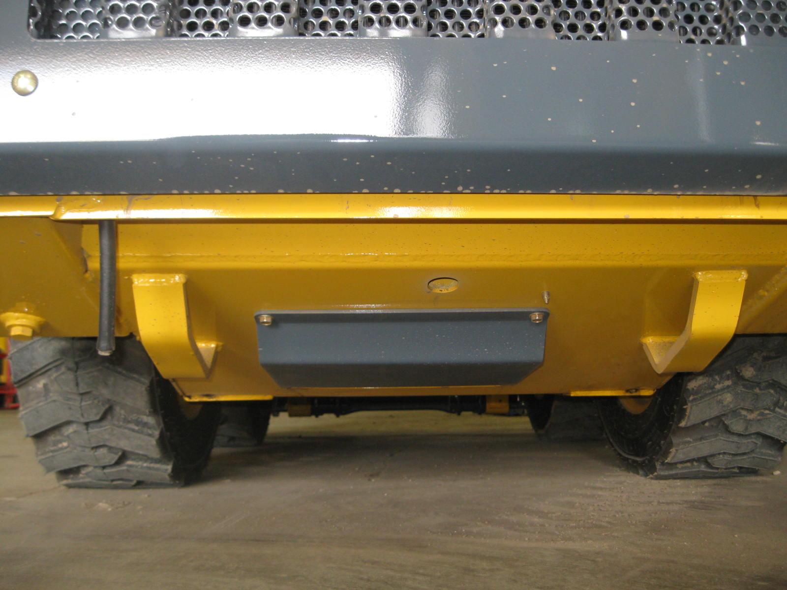
2. Install a catch pan of sufficient capacity under the oil reservoir (8gallons [30liters])
3. Remove the drain plug located on the bottom left of the oil reservoir.
4. Remove and replace the hydraulic oil filter.
5. Reinstall the drain plug.
6. Refill the reservoir until the oil is between the two lines on the dipstick gauge.
7. Start the engine and operate the hydraulic controls.
8. Stop the engine and check for leaks at the filter and reservoir drain plug.
9. Check the fluid level and add fluid if needed.
Cooling Systems
Important: Check the cooling system every day to prevent overheating, loss of performance or engine damage.
Checking Coolant Level
1.Open the rear door. Check the coolant level in the coolant recovery tank on the inside of the rear door. The coolant recovery tank must be 1/3 to 1/2 full with a cold engine and 2/3 to 3/4 full with a hot engine.
2. Allow the coolant to cool. Do not remove the cap when the coolant is hot. Serious burns may occur.
3. Add premixed coolant, 50% water and 50% ethylene glycol, to the recovery tank if the coolant level is low.
Cleaning Cooling System
1.Park the loader on a level surface, lower the lift arm and stop the engine. Allow the engine to cool.
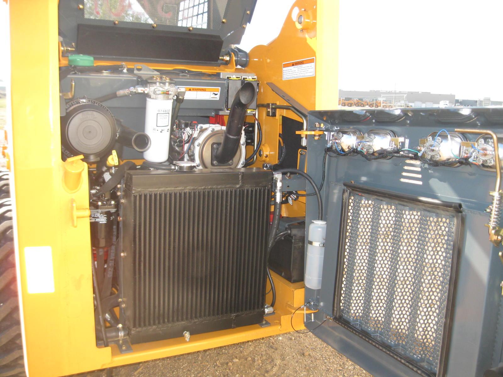
2. Open the rear door. Lift the engine cover.
3. Clean the radiator and oil cooler by blowing through the fins with high pressure water or air.
Note: The radiator can be tipped out for cleaning by loosening and rotating the over-center links on each side. This will also help in cleaning the oil cooler.
Draining/Flushing Cooling System
1.Open the rear door. Lift the engine cover.
2. Slowly remove the radiator cap, allowing pressure to dispel before removing completely.
Warning
Liquid cooling systems build up pressure as the engine becomes hot. Before removing the radiator cap, stop the engine and let the system cool. Remove the radiator cap only after the coolant has cooled. Remove the cap slowly or severe burns may result.
3. Remove the drain plug and drain the coolant into a suitable container.
4. Replace the drain plug.
Note: Protect the cooling system by adding premixed 50% water and 50% ethylene glycol to the system. This mixture will protect the cooling system to -34°F (-36°C).
5. Fill the radiator fully and the recovery tank half full with the premixed coolant.
6. Reinstall the radiator cap.
7. Run the engine until it is at operating temperature. Stop the engine and let it cool. Check the coolant level. Add more coolant if required.
Chaincases
The chaincase contains the drive sprockets and drive chains. There are two plugs in each chaincase. One is to drain the fluid and the other is to check the fluid level. Refer to the Maintenance Schedule chapter (page97) for change intervals. Refer to the Lubrication topic (page65) for information on oil type and quantity.
Checking and Adding Oil
1.Park the loader on a level surface. Stop the engine.
2. Remove the check plug from each chaincase housing. If the oil can be reached with the tip of your finger, the oil level is adequate.
3. If the level is low, add fluid through the check plug until the oil level reaches the edge of the hole. Reinstall the check plug.
Draining Oil
1.Raise the rear of the machine to aid in draining the chaincases.
2. Remove the drain plug on each chaincase and drain the oil into a suitable container.
3. Reinstall and tighten the drain plugs.
4. Refill the chaincases at the check plugs.
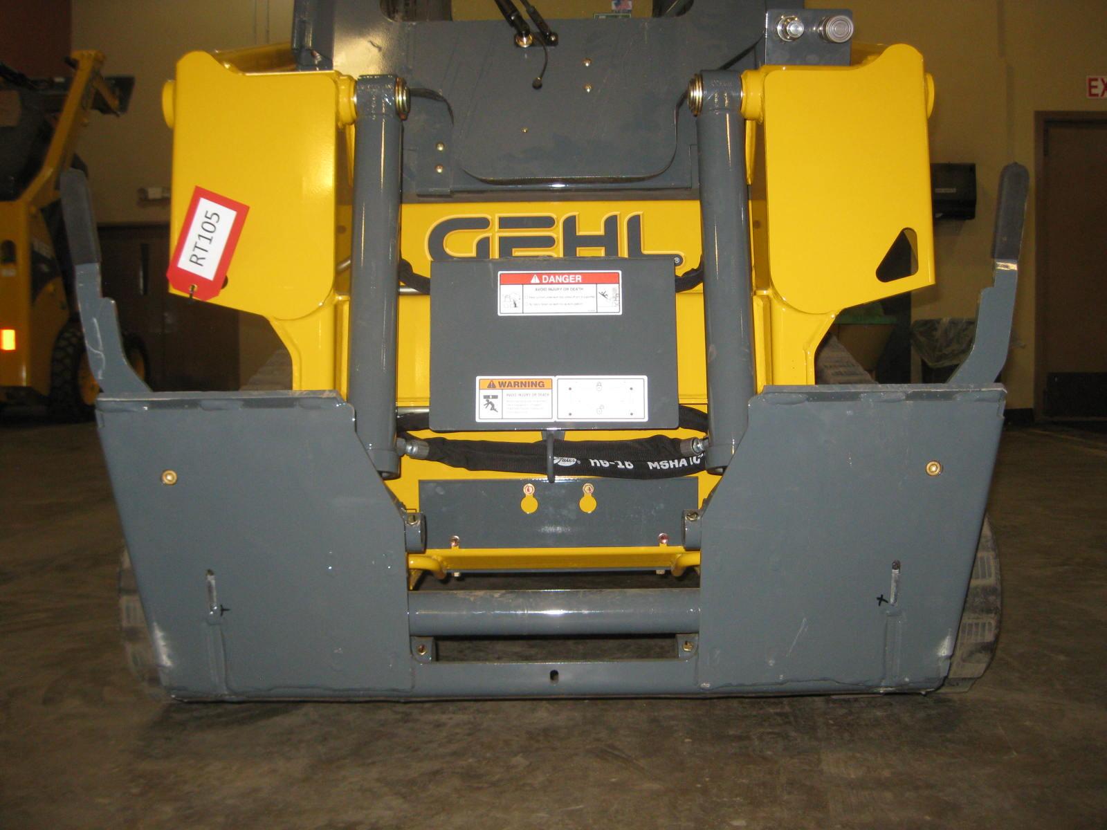
Seat and Restraint Bar Switches
Electrical switches in the seat and restraint bar must be closed (operator sitting in the seat and restraint bar lowered) to complete the circuit and start the engine.

Bucket Cutting Edge
The bucket cutting edge should be replaced when it is worn to within 1in. (25mm) of the bucket body.

Wheel Nuts
Wheel nut torque must be checked before initial operation and every two hours thereafter until the wheel mounting hardware torque stabilizes at the recommended setting of 120-130 ft-lbs (161-175 N·m). When tires are removed and replaced, this procedure must be repeated.
Tires
Rear tires usually wear faster than the front ones. To keep tire wear even, rotate the tires from front to rear and rear to front.
It is important to keep the same size tire on each side of the loader to prevent excessive wear on tires or other damage. If different sizes are used, each tire will be turning at different speeds, causing excessive wear. The tread bar of all tires must face the same direction.
Mounting Tires
Inflating or servicing tires can be dangerous. When possible, trained personnel should service and mount tires. To avoid possible death or serious injury, follow the safety precautions below.
Warning
1.Be sure the rim is clean and free of rust.
2. Lubricate the tire beads and rim flanges with a soap solution. Do not use oil or grease.
3. Use a clip-on tire chuck with remote hose and gauge, allowing you to stand clear while inflating the tire. Do not place your fingers on the tire bead or rim during inflation.
4. Never inflate beyond 35 psi (240 kPa) to seat the beads. If the beads have not seated by the time the pressure reaches 35 psi (240 kPa), deflate the assembly, reposition the tire on the rim, lubricate both parts and re-inflate. Inflation pressure beyond 35 psi (240 kPa) with unseated beads may break the bead or rim with explosive force sufficient to cause death or serious injury.
5. After seating the beads, adjust the inflation pressure to the recommended operating pressure.
6. Do not weld, braze or otherwise attempt to repair and use a damaged rim.