5 minute read
Engine Air Cleaner


Important: Failure to follow proper filter servicing instructions could result in catastrophic engine damage.
The air cleaner consists of an outer (primary) filter element and an inner (secondary) filter element. An air filter restriction indicator for monitoring the condition of the elements is located on the right side of the front of the air cleaner. If the air filter becomes restricted, this indicator will turn red to warn the operator that the element(s) require service. Push the reset button located on the end of the indicator after fitting a clean element. For replacement elements, refer to the “Replacement Parts” topic (page63).
Note: Before replacing the filter element(s), push the reset button on the indicator. Start the engine and adjust the throttle to full speed. If the indicator does not turn red, do not replace the element(s).
The outer element should be replaced only when the restriction indicator turns red. The inner element should be replaced every third time the outer element is replaced, unless the outer element is damaged or the inner element is dirty.
Along with a daily check of the restriction indicator, check the air cleaner intake hose and clamps, and the mounting bracket hardware to be sure they are properly tightened.
1.Restriction Indicator
2.Element Housing
3.Elbow Hose
4.Hose Connector
5.Sound Diffuser/Intake Suppressor
6.Air Intake Tube
1 2 3 4 5
1.Restriction Indicator
2.Element Housing
3.Inner Filter Element
4.Outer Filter Element
5.Element Cover
6.Dust Ejector
Access
1.Open the rear door and engine access cover.
2. Unlatch the clamps on the air cleaner and remove the cover. Clean out any dirt built up in the cover assembly.
Outer Element
1.Carefully pull the outer element out of the housing. Never remove the inner element unless it is to be replaced.
2. Clean out any dirt built up in the housing. Leave the inner element installed during this step to prevent debris from entering the engine intake manifold.
3. Replace the outer element.
Note: Manitou Group does not recommend cleaning the outer element.
4. Use a trouble light inside the outer element to inspect for spots, pinholes or ruptures. Replace the outer element if any damage is noted. The outer element must be replaced if it is oil- or soot-laden.
Inner Element
Note: Replace the inner element only if it is dirty or if the outer element has been replaced three times.
1.Before removing the inner element from the housing, clean out any dirt built up in the housing. Leave the inner element installed during this step to prevent debris from entering the engine intake manifold.
2. Remove the inner element.
Reinstallation
1.Check the inside of the housing for any damage that may interfere with the elements.
2. Be sure that the element sealing surfaces are clean.
3. Insert the element(s), making sure that they are seated properly.
4. Secure the cover to the housing with clamps.
5. Check the hose connections and be sure they are all clamped and tightened properly.
6. Reset the restriction indicator by pressing the reset button.
Engine Service
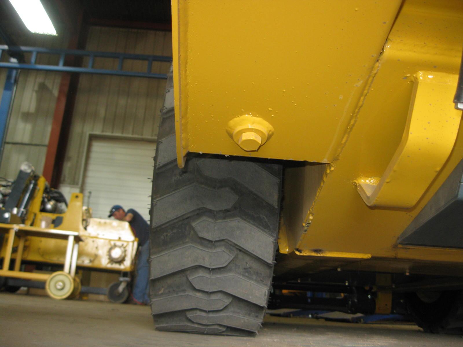
Check Engine Mounting Hardware
All bolts that secure the engine mounting brackets to the engine and the loader frame should be checked and re-tightened as necessary.
Warning
Allow hot engine and hydraulic system components to cool before servicing.

Checking Engine Oil Level
.
Open the rear door and engine access cover. Pull out the dipstick and check the oil level. Markings on the dipstick represent FULL and LOW (add oil) levels.
Refer to the Maintenance Interval Chart (page97) for the service interval for replacing the engine oil and filter.
Changing Engine Oil and Filter
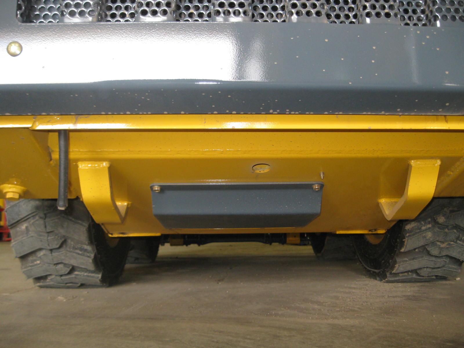
1.Run the engine until it is at operating temperature. Stop the engine. Remove the rear belly pan.

2. Remove the drain plug.
3. From the engine compartment, remove the oil filter. Clean the filter sealing surface.
4. Put clean oil on the new oil filter gasket. Install the filter and tighten 3/4 of a turn past the point where the gasket contacts the filter head.
5. Reinstall and tighten the drain plug.
6. Remove the oil cap and add the recommended oil. Refer to the “Lubrication” topic in this chapter for oil specifications and capacities.
7. Start the engine and let it run for several minutes at low idle. Stop the engine. Check for leaks at the oil filter, drain plug and remote oil drain hose. Check the oil level. Add oil if it is not at the top mark on the dipstick.
For a replacement element, refer to the “Replacement Parts” topic (page63).
Changing Fuel Filter
The engine has a fuel filter located on the left side of the engine. To change it:
1.Shut off the fuel supply by turning the fuel shutoff valve on top of the water trap.
2. Non-DPF Models: Shut off the return line by turning the valve on the fuel tank.
3. Remove the fuel filter element.
4. Lubricate new fuel filter element gasket with diesel fuel.
5. Install and tighten the filter element one-half turn past point the where the gasket contacts the filter head.
6. Turn shutoff valve on water separator to ON.
7. Non-DPF Models: Turn on the fuel supply at the fuel tank.
The engine is self-priming. To remove air before starting, turn the ignition key to the ON position for 30 seconds.
For a replacement element, refer to the “Replacement Parts” topic (page63).
Servicing Water Separator (DPF Models)
The water separator is located between the fuel tank and the main fuel filter and is used to remove finely dispersed water in diesel fuel. Check on a daily basis and drain if necessary. Water can be drained from the separator by opening the valve located at the bottom of the separator bowl.
Important: Water in the fuel system can cause severe engine damage. Drain water from the water separator anytime water is present.
To change the water separator filter, turn the plastic petcock located on top of the water separator a 1/4 turn to stop fuel flow. Unscrew the separator bowl from the housing and pull down on the existing filter to release it from the housing. Replace with a new filter and reinstall the bowl. Return the petcock on the water separator to the open position. Start the engine and check for leaks.
Servicing Water Separator (Non-DPF Models)
Periodically check for water in water separator by checking level of float in water separator bowl. If water is present:
1.Shut off the fuel supply by turning the fuel shutoff valve on top of the water separator.

2. Turn nut to release the bowl from the valve head. Dispose remaining fuel and water.
3. Clean bowl and filter element with warm water until all foreign material is removed. Replace fuel filter if damaged. Refer to Parts Manual for part number.
4. Place element onto valve head. Lubricate o-ring on bowl with diesel fuel and place on valve head. Turn nut to tighten.
5. Turn on fuel supply.
Releasing Water from Separator
1.Check red float located in the water separator bowl. If red float is raised, open valve on the bottom of the bowl to drain water.
2. Close valve quickly after float reaches the bottom of the bowl.
Spark Arrestor Muffler (Non-DPF Models)
Important: The loader is factory-equipped with a spark arrestor type muffler. Muffler maintenance is required to keep it in working condition. Refer to local laws and regulations for spark arrestor requirements.
1.Stop the engine, open the rear door and engine cover.
2. Remove the plug from the bottom of the muffler.
3. Block the outlet of the muffler with a non-combustible material.
4. Start the engine and run it for 10-15 seconds.
5. Stop the engine and remove the blockage.
6. Put anti-seize coating on the plug.
7. Reinstall and tighten the plug.
Alternator/Fan Belt
Refer to the separate engine manual for setting proper belt tension. If the belt is worn, cracked or otherwise deteriorated, replace the belt by following the procedure in the separate engine manual.
Engine Diagnostic Chart (DPF Models)
When detecting faults, the information center electronic display (page37) uses a diagnostic trouble code (DTC) screen to alert the operator to the occurrence of the fault conditions.
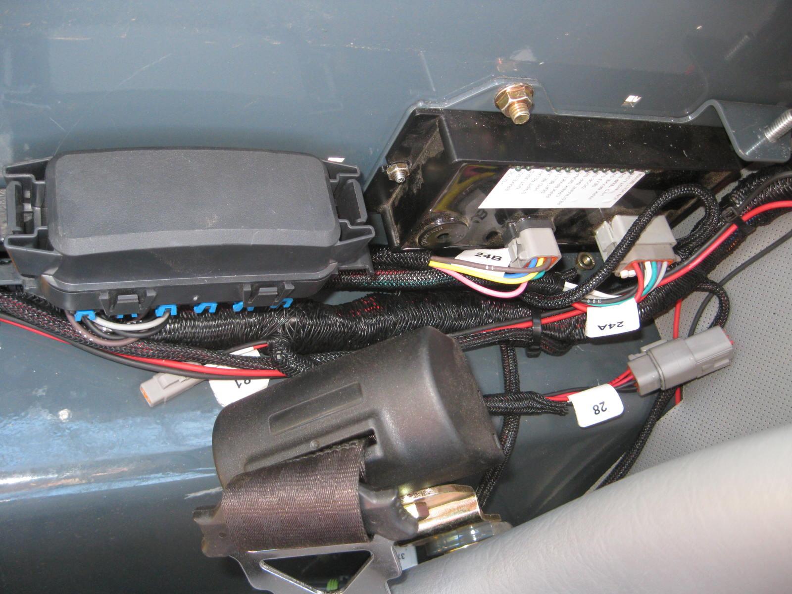
The data port for accessing the diagnostic trouble codes can be found underneath an electrical cover, right of the seat.
The following pages list descriptions, diagnostic trouble codes and fault codes for the engines.