15 minute read
Information Center Electronic Display Screens


Note: Values may not display for all parameters, depending upon installed options and equipment.
Table 2: Status, Maintenance and Error Code Screens
Display Mode Description
Status Screens
1234.5
Dual Gauge Display
A.Accumulated operation time.
Note: Time is displayed in hours, and accumulates when the engine is running.
B.Engine coolant temperature.
C.Amber error condition warning. Causes DM1/DM2 errors screen(s) to display. See page39.
D.Red critical error warning. Causes DM1/DM2 errors screen(s) to display. See page39.
E.Engine coolant temperature amber warning region. Indicates elevated coolant temperature.
F.Engine coolant temperature red stop warning region. Indicates serious coolant overheating condition.
Note: Running the engine in an overheated condition can damage the engine.
Quad Gauge Display
1234.5 12.528.0 1000
Table 2: Status, Maintenance and Error Code Screens Display
Single Gauge Display
Displays single real time operating parameters. Switch between parameters using the navigation button (M, Figure 17). Used for various functions, depending upon screen and context.
Secondary Screens
Regeneration Screens (DPF Models)
These screens are associated with Diesel Particulate Filter (DPF) regeneration procedures and maintenance. See “Diesel Particulate Filter (DPF) Regeneration Procedures (DPF Models)” on page55.
All Secondary Screens
Secondary screens are accessed by holding down the ok button (N, Figure 17) for 10 seconds while the Dual Gauge Display screen is displayed. Press the left/right side of navigation rocker button (M, Figure 17) to switch between secondary screens.
Revision Screen
Displays information center electronic display software information.
Table 2: Status, Maintenance and Error Code Screens
Units Screen
Press the top/bottom of navigation rocker button (M, Figure 17) to switch between SAE or metric units for values displayed in screens.
Language Screen
The press the top/bottom of navigation rocker button (M, Figure 17) to switch between English or Spanish language for values displayed in screens.
DM1 Screen
Displays engine, drive system, control, and safety system error code message information. Number of available messages is displayed at the top left of the screen (T). Use buttons (P and Q, Figure 17) to scroll through the messages. See “Engine Diagnostic Chart (DPF Models)” on page73 for specific error code details.
DM2 Screen
Continuation of error code message display along with DM1 Screen. Number of available messages is displayed at the top left of the screen (T). Use buttons (P and Q, Figure 17) to scroll through the messages. See “Engine Diagnostic Chart (DPF Models)” on page73 for specific error code details.
Before starting the engine and operating the loader, review and comply with all safety recommendations in the Safety chapter of this manual. Know how to stop the loader before starting it. Also, be sure to fasten and properly adjust the seatbelt(s) and lower the operator restraint bar.
Before Starting the Engine
Before starting the engine and running the loader, refer to the Controls and Safety Equipment chapter and become familiar with the various operating controls, indicators and safety devices on the loader.
Fuel
Use only ultra-low sulfur diesel fuel to maintain proper engine performance. Use of diesel fuel with more than 15 ppm of sulfur can potentially damage the engine. BioDiesel mixtures of up to a 7% (B7) are acceptable. Ultra-Low Sulfur Diesel (ULSD) fuel lubricity must have a maximum scar diameter of 0.45 mm, as measured by ASTM D6079 or ISO 12156-1, or a minimum of 3100 grams, as measured by ASTM D6078. Contact your fuel supplier for details.
Static electricity can produce dangerous sparks at the fuel-filling nozzle. Do not wear polyester, or polyester-blend clothing while fueling. Before fueling, touch the metal surface of the machine away from the fuel fill to dissipate any built-up static electricity. Do not re-enter the machine but stay near the fuel filling point during refueling to minimize the build-up of static electricity. Do not use cell phones while fueling. Make sure the static line is connected from the machine to the fuel truck before fueling begins.
Ultra-Low Sulfur Diesel (ULSD) poses a greater static ignition hazard than earlier diesel formulations. Avoid death or serious injury from fire or explosion; consult with your fuel or fuel system supplier to ensure the entire fuel delivery system is in compliance with fueling standards for proper grounding and bonding practices.
Starting the Engine
The following procedure is recommended for starting the engine:
1.Carefully step up onto the back of the bucket or attachment and grasp the handholds to enter the operator’s compartment.
2. Close the door, fasten the seatbelt(s) and lower the restraint bar.
3. Verify the following:
the lift/tilt, drive and auxiliary hydraulic controls are in their neutral positions,
the parking brake switch is ON.
Note: When the key is turned to the RUN position, an indicator lamp will light on the instrument panel and a chirp will sound momentarily to remind users to fasten the seatbelt
4. Turn the key to the START position.
Note: If temperature is below 32° F (0° C), see Cold-Starting Procedure, on page 46.
Important: Do not engage the starter for longer than 15 seconds at a time. Longer use can overheat and damage the starter. If the engine fails to start within 15 seconds, return the key to the OFF position or check for engine error codes. Allow the starter to cool for 20 seconds and repeat step 4.
After the engine starts, allow a five minute low idle warm-up period before operating the controls.
Important: Avoid extended engine idling after the engine reaches normal operating temperature to prevent frequent DPF regenerations. If the indicator warning lamps do not go off, stop the engine and investigate the cause.
Cold-Starting
If the temperature is below 32° F (0° C), the following is recommended to make starting the engine easier:
Replace the engine oil with API-CJ-4/SAE 5W-30 oil as recommended by the viscosity chart;
Make sure the battery is fully charged;
Install a block heater on the engine. Let the engine run for a minimum of five minutes to warm the engine and hydraulic fluid before operating the loader. A block heater is recommended for starting in temperatures of 14° F (-10° C) or lower. See your dealer for heater options.
Cold Starting Procedure
Warning
Do not use starting fluid (ether) with preheat systems. An explosion can result which can cause engine damage, injury or death.
1.Turn the key to the RUN position. If the preheat light on the right instrument panel comes on, wait for this symbol to go out.
2. Immediately turn the key to the START position.
3. If engine does not start, return key to OFF position and repeat steps 1 and 2.
Important: During cold start conditions, the recommended limit of continuous starter engagement is 15 seconds and the starter must never be energized for more than 30 seconds. If the starter is energized for 20-30 seconds, the loader should be turned off for one minute or longer. To protect the starter (DPF Models), the E-ECU system turns off the starter circuit if it is energized for 30 seconds or longer. The starter will remain de-energized for 30 seconds more before the loader can be restarted.
Upon a successful start, let the engine run for a minimum of five minutes to warm the engine and hydraulic fluid before operating the loader.
Cold Start Aids
At an ambient temperature of 32° F (0° C) or below, no starting aids are required. However, as with any diesel vehicle, using the recommended engine oil, maintaining a healthy battery and installing an engine block heater are sound practices to improve cold-starting performance and prolonging starter life.
At an ambient temperature of 14° F (-10° C) or below, a healthy battery is essential as glow cycles and cranking cycles can induce a substantial load on the battery during start. An engine block heater is recommended at this temperature to reduce starter load and improve the engine warm-up period prior to loader operation. Attempting to start the loader without a block heater will result in multiple glow/crank cycles or possible extended cranking time approaching 20 seconds.
At an ambient temperature of 5° F (-15° C) or below, a healthy battery is imperative. A recommended battery charger/maintainer applied before or during a start cycle will help maintain 12 V to the starter circuit during a potential long crank cycle of 20 seconds or more. A required block heater will reduce starter load, reduce crank time and improve the overall engine warm-up time during extreme cold starts.
Stopping the Loader
The following procedure is the recommended sequence for stopping the loader:
1.Check that the drive control handle(s) is (are) in neutral position.
2. Lower the lift arm and rest the attachment on the ground.
3. Turn throttle knob back to the low idle position (and release the throttle pedal for T-bar control machines). Allow the engine to idle for five minutes if the engine was operated under full load.
4. Turn the keyswitch to the OFF position and remove the key.
5. Move the lift/tilt control to verify that the safety interlock system is preventing movement.
6. Raise the restraint bar, unfasten the seatbelt(s) and grasp the handholds while climbing out of the operator’s compartment.
Note: The skid-steer loader is equipped with a spring-applied automatic parking brake. The parking brake is applied when the operator lifts the restraint bar, leaves the operator’s seat or shuts off the engine, or actuates the parking brake switch.
Parking the Loader
Park the loader away from traffic on level ground. If this is not possible, park the loader across the incline and block the tires to prevent movement.
Jump Starting the Engine
If the battery becomes discharged or does not have enough power to start the engine, use jumper cables and the following procedure to jump-start the engine.
Warning
The ONLY safe method for jump-starting a discharged battery is for TWO PEOPLE to perform the following procedure. The second person removes the jumper cables so that the operator does not have to leave the operator’s compartment with the engine running. NEVER make jumper cable connections directly to the starter solenoid of either engine. DO NOT start the engine from any position other than on the operator’s seat and then ONLY after being sure ALL controls are in “neutral.”
Closely follow the procedure, in order, to avoid personal injury. In addition, to protect your eyes wear safety glasses and avoid leaning over the batteries while jump-starting.
DO NOT jump-start the battery if it is frozen, because it may rupture or explode.
Note: BE SURE the jumper battery is a 12-volt D.C. battery.
1.Turn the keyswitches of both vehicles to OFF, be sure the vehicles are in “neutral” and NOT touching each other.
2. Connect the positive (+) jumper cable to the positive (+) battery terminal on the disabled loader first. DO NOT allow the positive clamps to touch any metal other than the positive (+) battery terminals.
3. Connect the other end of the positive jumper cable to the jumper vehicle’s battery positive (+) terminal.
4. Connect the negative (-) jumper cable to the jumper vehicle’s battery negative (-) terminal.
5. Make the final negative (-) jumper cable connection to the disabled loader’s engine block or loader frame (ground), such as the rear grille latch post –NOT to the disabled battery’s negative post. If connected to the engine, keep the jumper clamp away from the battery, fuel lines and moving parts.
6. Start the loader. If it does not start at once, start the jumper vehicle engine to avoid excessive drain on the booster battery.
7. After the disabled loader is started and running smoothly, have the second person remove the jumper cables (negative (-) jumper cable first) from the jumper vehicle’s battery and then from the disabled loader while being sure NOT to short the two cables together.
Allow sufficient time for the skid-steer loader alternator to build-up a charge in the battery before attempting to operate the loader or shut the engine off.
Changing Attachments
Warning
To prevent unexpected release of the attachment from the hitch, be sure to secure the latch pins by rotating the levers all the way to the hitch. Locking pins must be fully engaged through the holes in the attachment frame before using the attachment. The attachment could fall off if it is not locked on the hitch and cause serious injury or death.
The skid-steer loader features a All-Tach™ attaching mechanism for mounting a bucket or other attachment. Two latch levers engage the latch pins to secure the attachment.
Connecting an Attachment
1.Rotate the latch levers to a vertical position to fully retract the latch pins.
2. Start the loader engine and be sure the lift arm is lowered and in contact with the loader frame.
3. Align the loader squarely with the back of the attachment.
4. Tilt the hitch forward until the top edge of the hitch is below the flange on the back side of the attachment and centered between the vertical plates.
5. Slowly drive the loader forward and, at the same time, tilt the hitch back to engage the flange on the back side of the attachment.
6. Stop forward travel when the flange is engaged, but continue to tilt the hitch back to lift the attachment off the ground.
7. Exercise the MANDATORY SAFETY SHUTDOWN PROCEDURE (page6).
8. With the loader engine OFF, leave the operator’s compartment and rotate the latch levers all the way to the hitch to fully engage the latch pins.
Important: To check that the attachment is properly installed tilt the attachment forward slightly, apply downward pressure to the attachment prior to operating.
Connecting Auxiliary Hydraulic Couplings
Note: With the engine OFF, key in the ON position and the restraint bar down, the auxiliary hydraulic control can be moved to relieve any pressure in the hydraulic system.
The hydraulic couplers are located on the left lift arm. “A” port is pressure, “B” port is return when the auxiliary control is in the detent position.
Removing Attachments
1.Tilt the hitch back until the attachment is off the ground.
2. Exercise the MANDATORY SAFETY SHUTDOWN PROCEDURE (page6).
3. Relieve any hydraulic pressure in the auxiliary and attachment lines.
a.Turn the key switch, but do not start the engine.
b.With the restraint bar down, move the auxiliary hydraulic control back and forth. This will relieve the pressure in the hydraulic system.
4. With the engine OFF, leave the operator’s compartment, disconnect the auxiliary hydraulic hoses and rotate the latch levers completely vertical to fully retract the latch pins.
5. Start the engine and be sure that the lift arm is fully lowered and in contact with the loader frame.
6. Tilt the hitch forward and slowly back the loader away until the attachment is free from the loader.
Self-Leveling (optional)
The self-leveling feature is intended to automatically keep the attachment level while the lift arm is being raised. Self-leveling operates only when the lift arm is raised; when the lift arm is lowered, self-leveling is not activated.
Using a Bucket
WARNING
Always maintain a safe distance from electric power lines and avoid contact with any electrically charged conductor or gas line. Accidental contact or rupture can result in electrocution or an explosion. Contact the “Digger’s Hotline” or proper local authorities for utility line locations before starting to dig.
Driving over Rough Terrain
When traveling over rough terrain, drive slowly with the bucket lowered.
Driving on an Incline
When traveling up or down on an incline, travel with the heavy end pointing uphill. Try to avoid traveling on an incline, but always travel with the bucket as possible to maintain stability.
Loading a Bucket
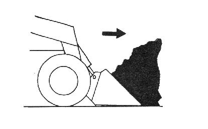
Approach the pile with the lift arm fully lowered and the bucket tilted slightly forward until the edge contacts the ground. Drive forward, lifting the lift arm and tilting back the bucket to fill it. Back away from the pile.
Always carry the loaded bucket with the lift arm resting on the loader frame. For additional stability when operating on inclines, always travel with the heavier end of the loader toward the top of the incline.
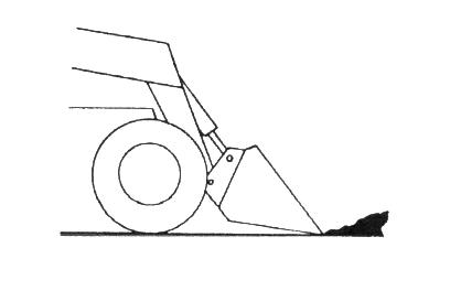
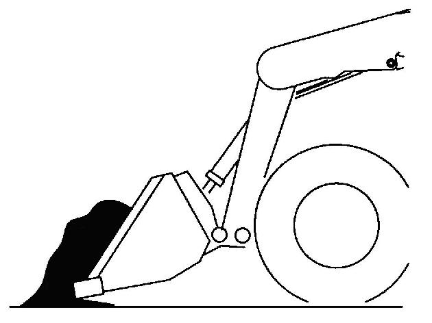
Digging with a Bucket
Approach the digging site with the lift arm slightly raised and the bucket tilted forward until the edge contacts the ground. Break the ground by driving forward and gradually lowering the lift arm. With the bucket filled, tilt the bucket back, and back the loader away from the material. Rest the lift arm against the loader frame before proceeding to the dumping area.
Dumping the Load onto a Pile
Carry a loaded bucket as low as possible until reaching the pile. Gradually stop forward motion and raise the lift arm high enough so that the bucket clears the top of the pile. Then slowly move the loader ahead, to position the bucket to dump the material on top of the pile. Empty the bucket and back the loader away while tilting the bucket back and lowering the lift arm.
Never push the controls into the float position with the bucket or attachment loaded or raised, because this will cause the lift arm to lower rapidly.
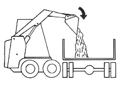
Dumping the Load Into a Box
Carry the loaded bucket low and approach the vehicle or bin. Stop your approach as close to the side of the box as possible while allowing for clearance to raise the lift arm and loaded bucket. Next, raise the lift arm until the bucket clears the top of the box and move the loader ahead, to position the bucket over the inside of the box, slowly dump the bucket. After the material is dumped, back away from the box while tilting the bucket back and lowering the lift arm.
Dumping the Load Over an Embankment
Warning
Do not drive too close to an excavation or ditch. Be sure the surrounding ground has adequate strength to support the weight of the loader and the load.
Carry the loaded bucket as low as possible while traveling to the dumping area. Stop the loader where the bucket extends half-way over the edge of the embankment. Tilt the bucket forward and raise the lift arm to dump the material. After the material is dumped, back away from the embankment while tilting the bucket back and lowering the lift arm.
Scraping with a Bucket
For scraping, the loader should be operated in the forward direction. Position the lift arm down against the loader frame. Tilt the bucket cutting edge forward at a slight angle to the surface to be scraped. While traveling slowly forward with the bucket in this position, material can flow over the cutting edge and collect inside the bucket.
Leveling the Ground
Drive the loader to the far edge of the area to be leveled. Tilt the bucket forward to place the bucket cutting edge at a 30 to 45degree angle to the surface to be leveled. Then place the lift arm into the “float” position and drive the loader rearward dragging the dirt and, at the same time, leveling it.

Note: The float (detent) position for T-Bar controlled loaders is reached by pushing the right handle all the way forward. For hand/foot controlled loaders, use your toes to push the front of the left pedal all the way down.
Warning
Check that the work area is clear of people and obstacles. Always look in the direction of travel.
Vibration Information
Compact construction equipment is generally used in harsh environments. This type of usage can expose an operator to uncomfortable levels of vibration. It is useful to understand exposure to vibration levels when operating compact equipment and what can be done to reduce vibration exposure. As a result, equipment operation can be more efficient, productive and safe.
An operator’s exposure to vibration occurs in two ways:
Whole-Body Vibration (WBV)
Hand-Arm Vibration (HAV)
This section will cover primarily WBV issues, because evaluations have shown that operation of mobile compact construction equipment on jobsites typically results in HAV levels less than the allowed exposure limit of 2.5 m/s2.
Employers in Member States of the European Union must comply with the Physical Agents (vibration) Directive, 2002/44/EC.
Effective control of vibration exposure for an operator involves more than just vibration levels on the machine. The job site, how the machine is used, and proper training all play important roles in reducing vibration exposure.
Vibration exposure results from:
worksite conditions
how the machine is operated
the machine characteristics
Common causes of high WBV vibration levels:
Using a machine that is improper for the task
Work site with potholes, ruts and debris
Improper operating techniques, such as driving too fast
Incorrect adjustment of the seat and controls
Other physical activities while using the machine
Vibration Measurement and Actions
The vibration directive places the responsibility for compliance on employers. Actions that should be followed by employers include:
Assess the levels of vibration exposure.
Determine from this assessment if operators will be exposed to vibration levels above the limits stated in the directive.
Take appropriate actions to reduce operator’s exposure to vibration.
Provide operators with information and training to reduce their exposure to vibration.
Keep good records and update operations and training on a regular basis. If the assessment concludes that vibration level exposure is too high, one or more of the following actions may be necessary:
1.Train operators
Perform operations (accelerating, steering, braking, etc.) in a smooth manner.
Adjust machine speed appropriately.
Adjust the controls, mirrors and seat suspension for comfortable operation.
Travel across the smoothest parts of the work site and avoid ruts and potholes.
2.Choose proper equipment for the job
Use machines with the proper power and capacity.
Select machines with good suspension seats.
Look for controls that are easy to use.
Ensure good visibility from the operator’s position.
3.Maintain the work site
Smooth ruts and fill potholes in traffic areas whenever possible.
Clean up debris frequently.
Vary traffic patterns to avoid exposure to rough terrain.
4.Maintain the equipment
Ensure correct tire pressures.
Check that seat suspension and all controls work smoothly and properly.
Vibration Levels
The following two tables show typical Whole-Body and Hand-Arm Vibration levels for the Gehl R105 servo-controlled skid-steer loaders with their different seat options.