8 minute read
Diesel Particulate Filter (DPF) Regeneration Procedures (DPF Models)

The Diesel Particulate Filter (DPF) treats exhaust emissions in compliance with Tier 4 / Stage 5 emission standards. The DPF filter relies on high exhaust temperatures. Periodic DPF maintenance (regeneration) is required, dependent upon machine operation load / temperature.
Note: Machines operated primarily at high loads and operating temperatures require less frequent DPF maintenance. Extended periods of engine idling rapidly increases DPF soot levels, requiring more frequent regeneration operations.
There are three modes of DPF regeneration:
• Passive / Assist Regeneration: Occurs automatically without operator input. Passive/assist regeneration does not affect machine operation.
• Reset Regeneration: Occurs automatically, but can be inhibited by the operator. Increases exhaust gas temperatures. Reset regeneration occurs approximately every 100 hours of operation. See “Reset Regeneration” on page56.
Note: Reset regeneration effectiveness is improved if the machine is operated at mid- to high-throttle settings when reset regeneration mode is in progress.
• Stationary Regeneration: Requires operator action to initiate and takes approximately 25-30 minutes to complete. See “Stationary Regeneration” on page57.
Important: The machine cannot be operated and must be parked in a well-ventilated area away from flammable materials when stationary regeneration is in progress. There is a possibility of carbon monoxide poisoning if stationary regeneration occurs in an enclosed space. Always perform stationary regeneration in a well-ventilated area.
WARNING WARNING
During regeneration, there will be high exhaust gas temperatures, even at low load. Stay clear of the DPF during regeneration.
Reset Regeneration
Important: Reset regeneration can be prevented from occurring. See “Reset Regeneration Inhibit” on page56. Reset regeneration occurs automatically (unless inhibited) approximately every 100 hours of operation.
Note: Reset regeneration effectiveness is improved if the machine is operated at mid- to high-throttle settings while regeneration is in progress.
When reset regeneration occurs, the DPF in-progress (elevated temperature) symbol (K, Figure 9) displays on the screen.
1234.5
Reset Regeneration Inhibit
DPF regeneration inhibit prevents reset regeneration from occurring. Permanently inhibiting regeneration is not recommended, as this will eventually cause significant reduction in engine power and will force premature DPF soot filter replacement.
Caution
To temporarily inhibit reset regeneration, hold down button (U, Figure 10) until the strikethrough in the Reset Regeneration symbol (W) turns to red.
Note: DPF in-progress (elevated temperature) symbol (K, Figure 9) will not be displayed when reset regeneration is inhibited.
Stationary Regeneration
Stationary regeneration may be periodically required to reduce DPF soot build-up. The frequency of stationary regeneration is dependent upon machine operation and engine load. The machine cannot be used during stationary regeneration and cannot be moved without interrupting the stationary regeneration process.
When stationary regeneration needs to be performed, the regeneration request screen (Figure 11) displays on the information center electronic display.
Note: The stationary regeneration request screen can be temporarily dismissed by pressing the reset regeneration inhibit button (U, Figure 10) for 3 seconds. Until the previous screen displays. The stationary regeneration request screen will return 1 minute after being dismissed, for as long as the request remains active.
Important: Perform stationary regeneration as soon as possible when the stationary regeneration request screen displays. Postponing stationary regeneration for extended periods will cause significant reduction in engine power and will force premature DPF filter core replacement.
To proceed with stationary regeneration (Figure 12):
1.Park the machine in a safe, wellventilated location away from flammable materials.
2.The following conditions need to be met before stationary regeneration continues:
A.Press the button on the control keypad (page37) or lift the operator restraint bar to apply the parking brake. A checkmark is displayed next to the parking brake symbol (A).
B.When engine coolant has reached operating temperature (above 140° F / 60° C, a checkmark is displayed next to the coolant temperature symbol (B).
C.Place throttle controls to the lowest speed setting. A checkmark is displayed next to the engine RPM symbol when the engine is running at low idle.
3.When all three checkmarks (A, B & C)are displayed on the Stationary Regeneration screen, press and hold the button (Z) until the Stationary Regeneration In-Progress screen displays (Figure 13).
Note: Stationary regeneration can be interrupted at any time by releasing the parking brake, advancing the throttle, or stopping the engine. Stationary regeneration must start again from the beginning if it is interrupted.
Stationary regeneration completion
22 % percentage is displayed as during the stationary regeneration progresses. Progress percentage disappears when stationary regeneration completes.
Note: Stationary regeneration takes approximately 25-30 minutes.
Caution
It is not necessary to stay in the machine during stationary regeneration. Keep the machine under observation while regeneration is in progress in case of malfunction. Keep bystanders away from the machine while regeneration is in progress.
Forcing Stationary Regeneration
Stationary regeneration can be performed at any time after 50 operating hours following the previous stationary regeneration.
To perform stationary regeneration ondemand:
Press button (Y, Figure 14) associated with the DPF regeneration symbol (X), until the regeneration screen displays. Refer to “Stationary Regeneration” on page57 to proceed with stationary regeneration.
DPF Maintenance
DPF soot filter replacement is required when the DPF (Diesel Particulate Filter) Service Screen (Figure 15) displays.
Note: Contact your dealer when the DPF Service screen displays.
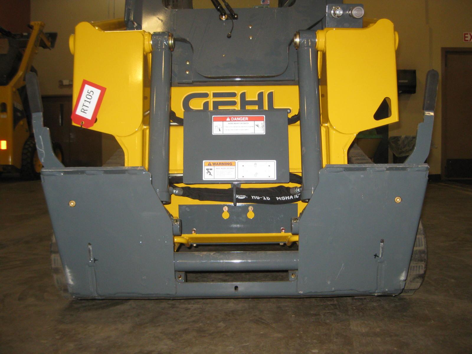
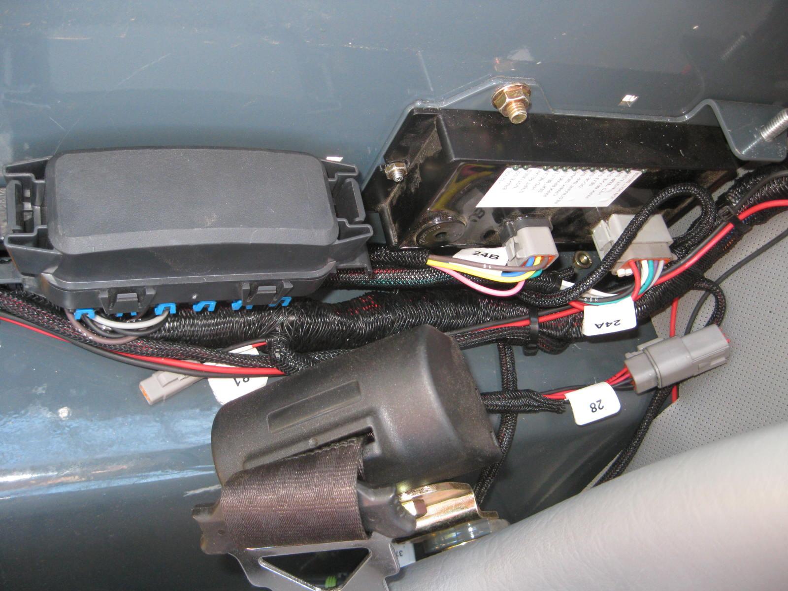
Back-Up Alarm
A back-up alarm system is optionally available which serves to warn people working in the area around the machine of the machine’s rearward movement. The back-up alarm is installed within the engine compartment on the inside surface of the rear door. The alarm emits a tone whenever the machine begins to move in the rearward direction.
Before servicing the machine, unless expressly instructed to the contrary, exercise the MANDATORY SAFETY SHUTDOWN PROCEDURE (page6).
After service has been performed, be sure to restore all guards, shields and covers to their original positions before resuming loader operation.
This Service chapter details procedures for performing routine maintenance checks, adjustments and replacements. Most procedures are referred to in the Troubleshooting and Maintenance chapters of this manual. Refer to the Maintenance Interval Chart (page 111) for service intervals. Refer to the separate engine manual for engine-related adjustments, lubrication and service procedures.
Note: All service procedures, except those described under the Dealer Services topic are owner-operator responsibilities.
Important: Always dispose of waste lubricating oils and hydraulic fluids according to local regulations or take to a recycling center for disposal. Do not pour onto the ground or down the drain.
Dealer Services
The following areas of component service, replacement and adjustments require special tools and knowledge for proper servicing and should be performed only by your authorized Gehl skid-steer loader dealer: hydrostatic drive components, hydraulic system pumps, valves, hydraulic cylinders, electrical components (other than battery, fuses or relays).
1.Air Cleaner
2.Exhaust Tube
3.Radiator/Cooler
4.Coolant Recovery Tank
5.Hydraulic Oil Filter
6.Engine Oil Dipstick
7.Engine Oil Fill Cap
8.Engine Oil Filter
9.Fuel Filter
10.Fuel Pump
11.Water Trap
12.DPF Cannister
Figure2 Engine CompartmentNon-DPF Models
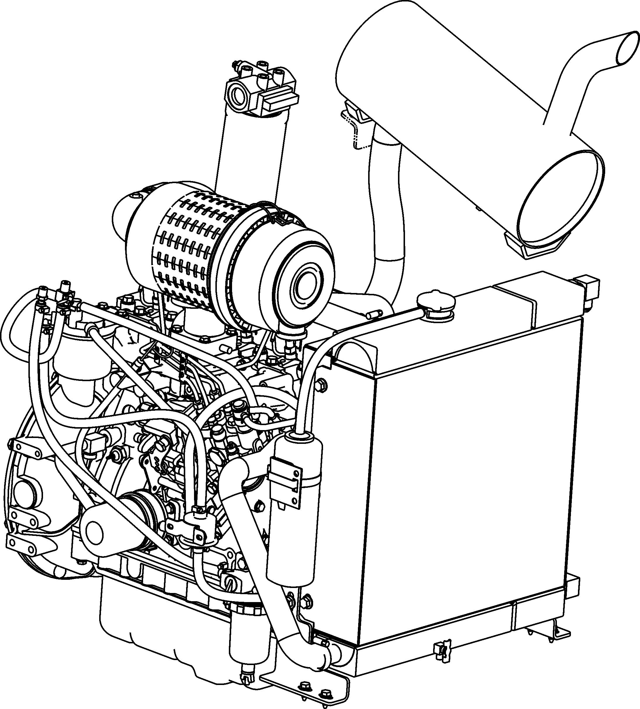
1.Air Cleaner
2.Muffler
3.Radiator/Cooler
4.Coolant Recovery Tank
5.Hydraulic Oil Filter
6.Engine Oil Dipstick
7.Engine Oil Fill Cap
8.Engine Oil Filter
9.Fuel Filter
10.Fuel Pump
11.Water Trap
Tilting Back the ROPS/FOPS
For service, unbolt the two anchor bolts at the front of the ROPS/FOPS and tilt it back slowly, moving the control handles out of the way. A gas-charged spring helps tilt it back. A self-actuating lock mechanism engages to lock the ROPS/FOPS in a rolled-back position. To lower the ROPS/FOPS, apply upward force on it while pulling the lock mechanism handle toward the front of the loader. Lower the ROPS slowly onto the chassis, moving the control handles out of the way. Reinstall the anchor bolts, washers and locknuts.

Never operate the loader with the ROPS/FOPS removed or locked back. Be sure the lock is securely engaged when the ROPS/FOPS is tilted back. Properly support the ROPS/FOPS when unlatching the lock mechanism and lowering the ROPS/FOPS. Be sure to reinstall the anchor bolts, washers and locknuts before resuming loader operation.
Loader Raising Procedure
To raise the skid-steer loader so all four tires are off the ground, use the procedure below:
Do not rely on a jack or hoist to maintain the “raised” position without additional blocking and supports. Serious personal injury could result from improperly raising or blocking the skid-steer loader.
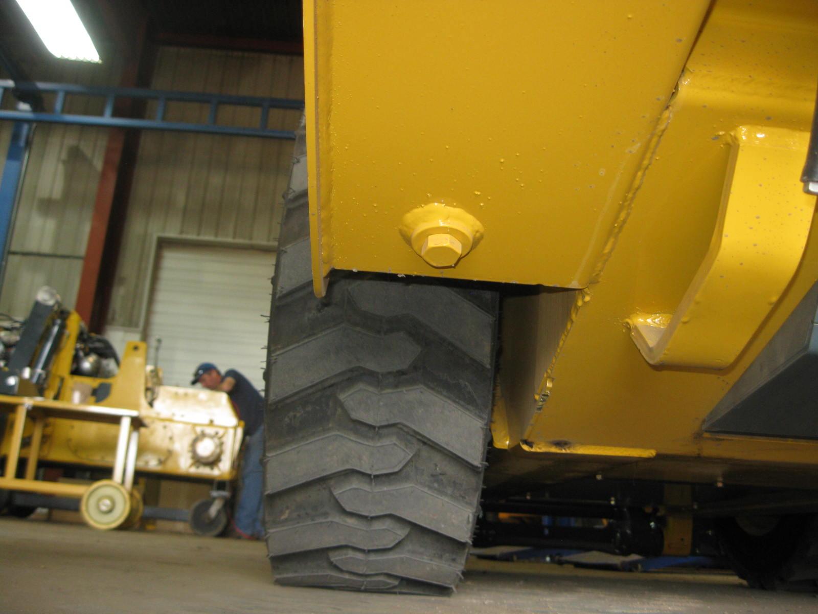
1.Using a jack or hoist capable of lifting the fully-equipped weight of the loader (with all attached options), lift the rear of the loader until the rear tires are off the ground.
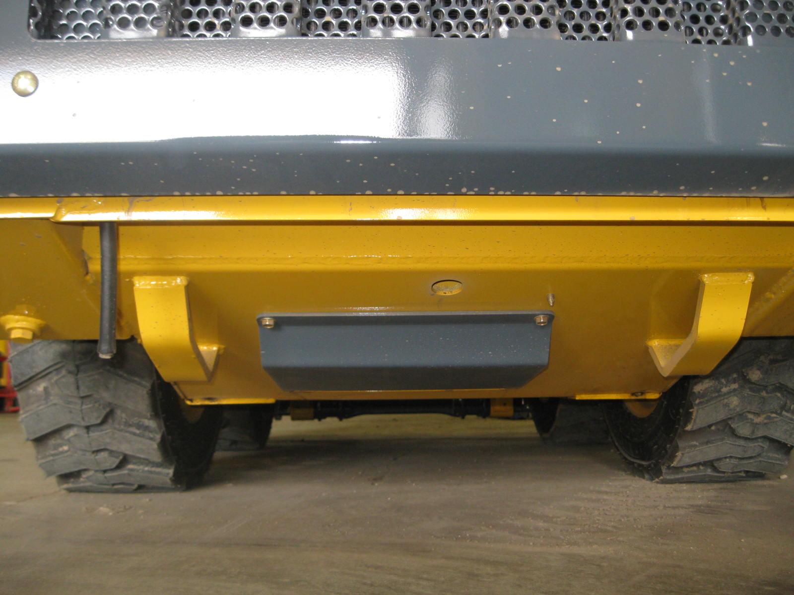
2. Stack wooden blocks under the flat part of the loader chassis. They should run parallel with, but not touch, the rear tires (Figure4).
3. Slowly lower the loader until its weight rests on the blocks. If the tires still touch the ground, raise the loader again, add more blocks and lower again.
4. Repeat Steps 1 through 3 for the front end. When the procedure is finished, all four tires will be off the ground so they can be removed.
Loader Lowering Procedure
When service or adjustment procedures are complete, the skid-steer loader can be taken down from the “raised” position. To lower the loader onto its tires:
1.Using a jack or hoist, raise the front of the loader until its weight no longer rests on the front blocks.
2. Carefully remove the blocking under the front of the loader.
3. Slowly lower the loader until the front tires are resting on the ground.
4. Repeat Steps 1 through 3 for the rear of the loader. When the procedure is finished, all four tires will be on the ground and the blocks removed from under the loader.
Replacement Parts
Note: Part numbers may change. Your Gehl dealer will always have the latest part numbers.
Adjustments
Control Handles
The control handles do not require routine adjustment. Refer to the Service Manual for the initial setup procedure.
Fuel Sender
The fuel sender, located in the fuel tank, sends a signal to the fuel gauge indicating the amount of fuel left in the fuel tank. Check the fuel sender periodically to ensure that the mounting screws are tight and that there is no fuel seepage around the gasket. If replacement is required, apply an RTV or gasket sealant around the gasket when restoring the fuel sender.
Drive Chains
The drive chains do not require routine adjustment. Refer to the Service Manual for the initial setup procedure.
Removing Foreign Material
The loader should be cleared daily of dirt and other foreign materials in the following areas:
•around the lift cylinders
•at the front of the loader
•on the hitch, especially around tilt cylinder
•around the hydraulic oil reservoir breather
•in the engine compartment
•in the operator’s compartment
Important: Build-up of foreign materials in these areas can interfere with the operation of the loader, cause component damage or become a fire hazard.
Lubrication
Listed below are the locations, temperature ranges and types of recommended lubricants to be used when servicing this machine. Refer to the separate engine manual for more information regarding recommended engine lubricants, quantities required and grades.
Hydraulic System
Use Petro Canada HVI60, Mobil DTE 15M or equivalent, which contain anti-rust, anti-foam and anti-oxidation additives, and conforms to ISO VG46.
Capacity: 8 U.S. gallons (30,0 liters)
Use SAE grade 10W-30 motor oil.
Chaincase Oil
Grease Fittings
Capacity (each side): 6 U.S. quarts (5,7 liters)
Use lithium based grease
Conventional oils - select the oil viscosity based on the ambient temperature where the engine is being operated. See SAE viscosity chart.
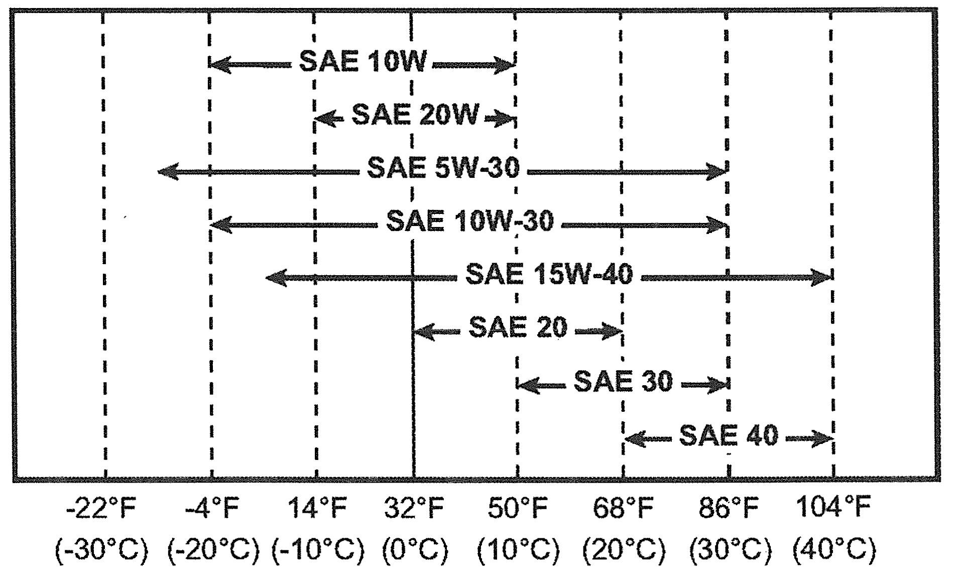
Full Synthetic Oil 0W-40. Do not mix oil types.
Engine Oil

API-CK-4 preferred API-CJ-4 acceptable
Capacity: 7.6 U.S. quarts (7,2 L)
Refer to the following figure for grease fitting locations. Wipe dirt from the fittings before greasing them to prevent contamination. Replace any missing or damaged fittings. To minimize dirt build-up, avoid excessive greasing.
1.Lift arm pivots (2)
2.Lift cylinder pivots (4)
3.Tilt cylinder pivots (2)

Grease Hitch, Hitch-related Cylinder Pivots and Latch Pins (page65)
Grease Lift Arm Pins (page65)
Check Oil Level in Chaincases (page81)
Change Engine Oil and Filter (page71)
Change Hydraulic Oil Filter (page79)
Change Hydraulic Oil (page79)
Change Chaincase Oil (page81)
Check and Drain Water Separator (page71)
Replace Filter in Water Separator (page71)
Perform the procedure at 1000 hours.