6 minute read
Instrument Panel (Non-DPF Models)

The instrument panel contains the following switches and indicators. Symbols on the panel represent various functions and conditions, and are visible only when indicator lamps are on.
1.Hourmeter – Displays the total operating hours on the loader.
2.Fuel Level Gauge – Displays the amount of fuel in the tank.
3.Engine Coolant Temperature Gauge –Indicates the engine coolant temperature.
Note: Items 4 through 9 are indicator lamps which display the following:
4.Fasten Seatbelt – A momentary visual (and audible) indicator to remind the operator to fasten the seatbelt.
5.Engine Oil Pressure – Lights if the engine oil pressure drops too low, warning the operator to immediately stop the engine and determine the cause for the pressure drop. During normal operation, this indicator should be OFF.
6.Battery – Lights if the charging voltage is too high or too low. During normal operation, this indicator should be OFF.
7.Preheat Indicator Lamp – Lights when the preheat switch is pressed. During normal operation, this indicator should be OFF.
8.Engine Coolant Temperature – Lights if the engine coolant becomes too hot, warning the operator to stop the engine. Allow the engine to cool, determine the cause for the high temperature and correct the problem before restarting the engine. During normal operation, this indicator should be OFF.
9.Hydraulic Oil Temperature – Lights if the hydraulic oil becomes too hot, warning the operator to stop engine. Allow the hydraulic system to cool and determine the cause of the high temperature. During normal operation, this indicator should be OFF.
10.Keyswitch – In a clockwise rotation, these positions are:
OFF Position – With the key vertical, power from the battery is disconnected to the controls and instrument panel electrical circuits. This is the only position the key can be inserted or removed from the keyswitch.
ON (or Run) Position – With the key turned one position clockwise from vertical, power from the battery is supplied to all control and instrument panel electrical circuits.
START Position – With the key turned fully clockwise, the electric starter energizes, start the engine. Release the key to the RUN position after the engine starts.
Note: The engine cannot be started unless the operator is sitting in the seat and the restraint bar is lowered.
11.Parking Brake Switch – Used to manually apply the parking brake. The red indicator on the switch lights when the parking brake is applied.
12.Light Switch – Controls all the lights on the loader. Symbols denote the four positions of the light switch. In a clockwise direction these are:
•OFF
•Tail Lights ON
•Front Work Lights with Tail Lights ON
•both Front and Rear Work Lights
For the lights to function, the keyswitch must be in the RUN position.
13.Circuit Breakers – Four circuit breakers on the instrument panel protect the loader’s electrical circuits.
Important: Do not attempt to defeat the circuit protection by jumping across a circuit breaker or by using a higher amperage circuit breaker.
14.Accessory Outlet – 12-volt DC power outlet.
T-Bar Controls
The loader may be equipped with T-bar controls (Figure10). The left T-bar controls the drive and the right T-bar controls the lift/tilt.
Drive Controls
Forward, reverse, speed and turning maneuvers are accomplished by movement of the left T-bar. To go forward, push the control forward; for reverse, pull the control rearward. To turn right, turn the control clockwise; to turn left, turn the control counterclockwise. For gradual turns, move the T-bar slightly forward or rearward. For sharp turns, turn the control clockwise or counterclockwise.
Figure10 T-Bar Controls
Moving the T-bar farther from neutral increase the speed steadily to the maximum travel speed. Tractive effort decreases as speed increases. To get maximum tractive effort, move the T-bar only slightly away from the neutral position. The engine will stall if the control is moved too far forward when loading the bucket.
Be sure the controls are in neutral before starting the engine. Operate the controls gradually and smoothly. Excessive speed and quick control movements without regard for conditions and circumstances are hazardous and could cause an accident.
Lift/Tilt Control
Moving the lift arm and tilting the attachment are accomplished by movement of the right T-bar. To raise the lift arm, pull the control straight rearward; to lower the lift arm, push the control straight forward. To tilt the attachment forward and downward, twist the control clockwise; to tilt the attachment up and back, twist the control counterclockwise..
Note: The speed of the lift/tilt motion is directly proportional to the amount of T-Bar movement and engine speed.
To place the lift arm into the detent (“float”) position, push the right T-Bar all the way forward into the detent. This position allows the lowered lift arm to “float” while traveling over changing ground conditions.
Never push the right control handle fully forward to detent the float control with the attachment raised, because this will cause the lift arm to lower very rapidly.
Hand/Foot Controls
The loader may be equipped with hand/foot controls (Figure11). The control grips control the drive and the foot pedals control the lift/tilt.

Drive Controls
Figure11 Hand/Foot Controls
1. Left Drive Control Handle
2. Right Drive Control Handle
3. Tilt Control Foot Pedal
4. Lift Control Foot Pedal
Forward, reverse, speed and turning maneuvers are accomplished by movement of the control grips. To go forward, push both control grips forward; for reverse, pull both control grips rearward. For turning, move one control grip farther forward or rearward than the other control grip. Turn direction is determined by which control grip is moved farther forward. To turn left, move the right control grip farther forward than the left control grip; to turn right, move the left control grip farther forward than the right control grip. For sharp turns, move the control grips in opposite directions.
Moving the control grips farther from neutral increases the speed steadily to the maximum travel speed. Tractive effort decreases as speed increases. For maximum tractive effort, move the control grips only slightly away from the neutral positions. The engine will stall if the control grips are moved too far forward when loading the bucket.
Be sure the controls are in neutral before starting the engine. Operate the controls gradually and smoothly. Excessive speed and quick control movements without regard for conditions and circumstances are hazardous and could cause an accident.
Lift/Tilt Controls
Moving the lift arm and tilting the attachment are accomplished by movement of the foot pedals. The left pedal raises and lowers the lift arm; the right pedal tilts the attachment. To raise the lift arm, push down on the back of the left pedal with your left heel; to lower the lift arm, push down on the front of the left pedal with the toes of your left foot. To tilt the attachment forward and down, push down on the front of the right pedal with the toes of your right foot; to tilt the attachment up and back, push down on the back of the right pedal with your right heel.
Note: The speed of the lift/tilt motion is directly proportional to the amount of pedal movement and engine speed.
To place the lift arm in the detent (“float”) position, use your toes to push the left pedal all the way down into the detent. This position allows the lowered lift arm to “float” while traveling over changing ground conditions.
Warning
Never push the left pedal into the float position with the attachment loaded or raised, because this will cause the lift arm to lower rapidly.
Auxiliary Hydraulic Controls
Auxiliary hydraulics are used with attachments that have a mechanism requiring hydraulic power.
Important: Always be sure the auxiliary hydraulic control is in neutral before starting the loader or removing the auxiliary hydraulic couplers.
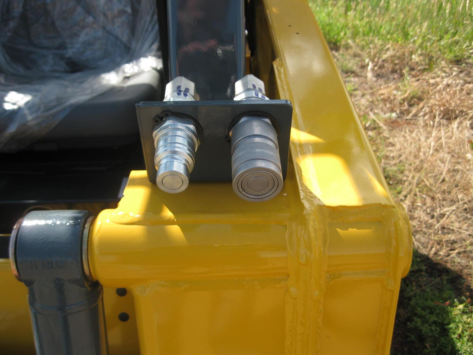
Note: When ignition power is interrupted, auxiliary hydraulic function is reset to OFF.
Couplers are located on the left lift arm. “A” port is pressure, “B” port is return when the auxiliary control is in the detent position (refer to page45).
T-Bar Controlled Loaders
A foot pedal is used to control the direction of oil flow.


Hand/Foot Controlled Loaders
The right handle controls the direction of oil flow. A locking pin locks it in the up position for continuous operation.
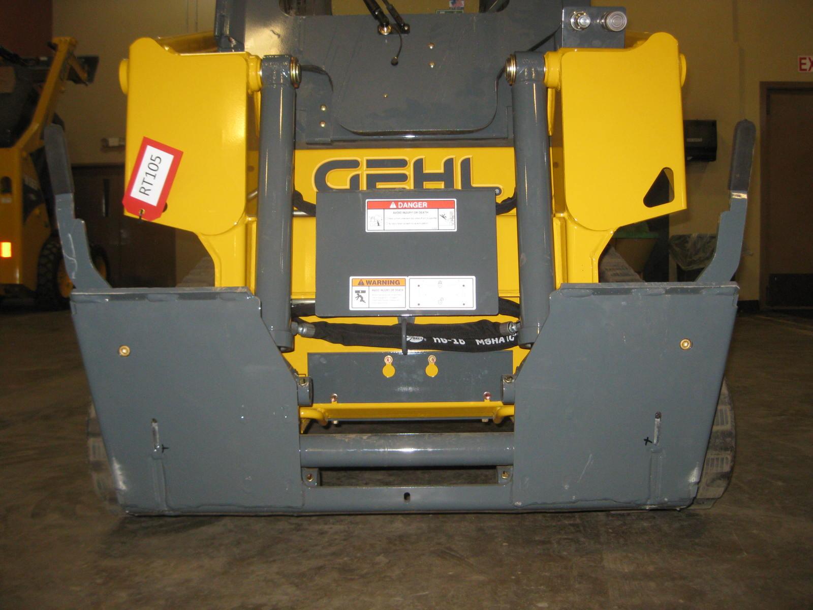
Attachment Mounting
The Gehl loader is equipped with a two-pin All-Tach™ attachment bracket for mounting a bucket or other attachment. Two latch levers secure the attachment. Rotate the levers until they are horizontal to engage the latch pins. Rotate the levers until they are vertical to disengage the latch pins.

To prevent unexpected release of the attachment from the hitch, be sure to secure the latch pins by rotating the levers all the way to the hitch.
Warning
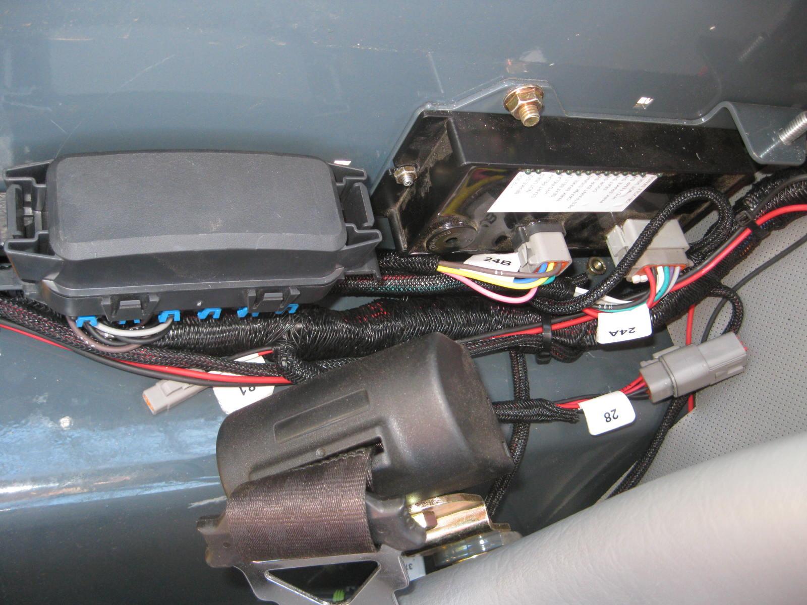
Electrical Battery Disconnect Switch (optional)
An optional electrical battery disconnect switch is located inside the engine compartment on the left side and forward of the fuse panel. Turn the switch to the OFF position to disconnect the battery from the electrical system.