7 minute read
CONTROLS AND SAFETY EQUIPMENT


Become familiar with and know how to use all safety devices and controls on the skid-steer loader before operating it. Know how to stop loader operation before starting it. This Gehl loader is designed and intended to be used only with a Gehl attachment or a Manitou Group-approved referral attachments or accessories. Manitou Group cannot be responsible for operator safety if the loader is used with a non-approved attachment.
Guards and Shields
Whenever possible and without affecting loader operation, guards and shields are provided to protect against potentially hazardous areas. In many places, safety decals are also provided to warn of potential hazards and/or to display special operating procedures.
Read and thoroughly understand all safety decals on the loader before operating it. Do not operate the loader unless all factory-installed guards and shields are properly secured in place.
Operator Restraint Bar
Lower the operator restraint bar after entering the operator’s compartment and sitting in the seat. The restraint bar is securely anchored to the ROPS/FOPS. The operator must be seated with the restraint bar in its lowered position to start or operate the skid-steer loader. Refer to Safety Interlock System on page 20 for more information.
The right and left portions of the restraint bar system can be adjusted independent of one another by pushing the locking lever on the lower inside of either pad. The restraint pads can then be adjusted to the desired position. The restraint pads lock in place when the locking lever is released.
Caution Warning Warning
Never defeat the operator restraint bar or seat switch electrically or mechanically. Always wear the seatbelt.
Operator’s Seat
Suspension seat (optional): A weight adjustment knob is provided for individual operator adjustment.
Upper-Torso Restraint
1.Restraint Bar
2.Seatbelt
3.Seat Adjustment Level
ALWAYS wear the upper-torso restraint when operating in High speed.
The seat belt should always be fastened during operation.
Important: Inspect the seat belt(s) for damage before use, and replace if damaged. Keep seatbelt(s) clean. Use only soap and water to wash seat belt(s). Cleaning solvents can cause damage to seatbelt(s).
Safety Interlock System
NEVER defeat the safety interlock system by mechanically or electrically bypassing any switches, relays or solenoid valves.
An interlock system is used on the loader for operator safety. Together with solenoid valves, switches and relays, the interlock system:
Prevents the engine from starting unless the operator is sitting on the seat and the operator restraint bar is down.
Disables the lift arm, attachment tilt and wheel drives when the operator leaves the seat, turns the keyswitch to OFF or raises the restraint bar.
Disables auxiliary hydraulic system when the restraint bar is raised or the keyswitch is OFF.
Note: The auxiliary hydraulic circuit can be detented in the “ON” position for continuous operation with the restraint bar raised and operator out of the seat. (See Auxiliary Hydraulic Controls, page 42.)
Testing the Safety Interlock System
Before leaving a parked machine, check the safety interlock system for proper operation:
Restraint Bar
With the engine running, raise the restraint bar. Move each of the controls. There should be not more than a slight movement of the lift arm, attachment and machine. If there is any significant movement, troubleshoot and correct the problem immediately. Contact your dealer if necessary.
Seat Switch
With the engine off and the restraint bar lowered, unfasten the seatbelt. Lift your weight up off the seat. Try to start the engine. If the engine starts, turn off the engine, and troubleshoot and correct the problem. Contact your dealer if necessary.
ROPS/FOPS
The ROPS/FOPS (Roll-Over/Falling Object Protective Structure) is designed to provide protection for the operator from falling objects and in a tip over accident, if the operator is secured inside the operator’s compartment by the seatbelt and restraint bar.
Warning
Never operate the loader with the ROPS/FOPS removed or locked back.
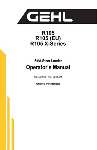
Parking Brake
This skid-steer loader is equipped with a spring-applied, hydraulic-released parking brake. The parking brake engages when the operator lifts the restraint bar, exits the seat or shuts off the engine. The brake can also be applied manually by using the switch located on the right instrument panel. A red indicator in the switch lights when the parking brake is applied.
Horn
On hand/foot loaders, pressing the right button on the left control handle sounds the horn. On T-bar loaders, pressing the bottom button on the left control handle sounds the horn.

Rear Window Emergency Exit
The ROPS rear window has three func tions: noise reduction, flying objects bar rier and emergency exit.
To use the emergency exit, pull on the yellow warning tag at the top of the window and remove the seal. Push or kick out the window and then exit.
See your local automotive glass specialist to reinstall the window.

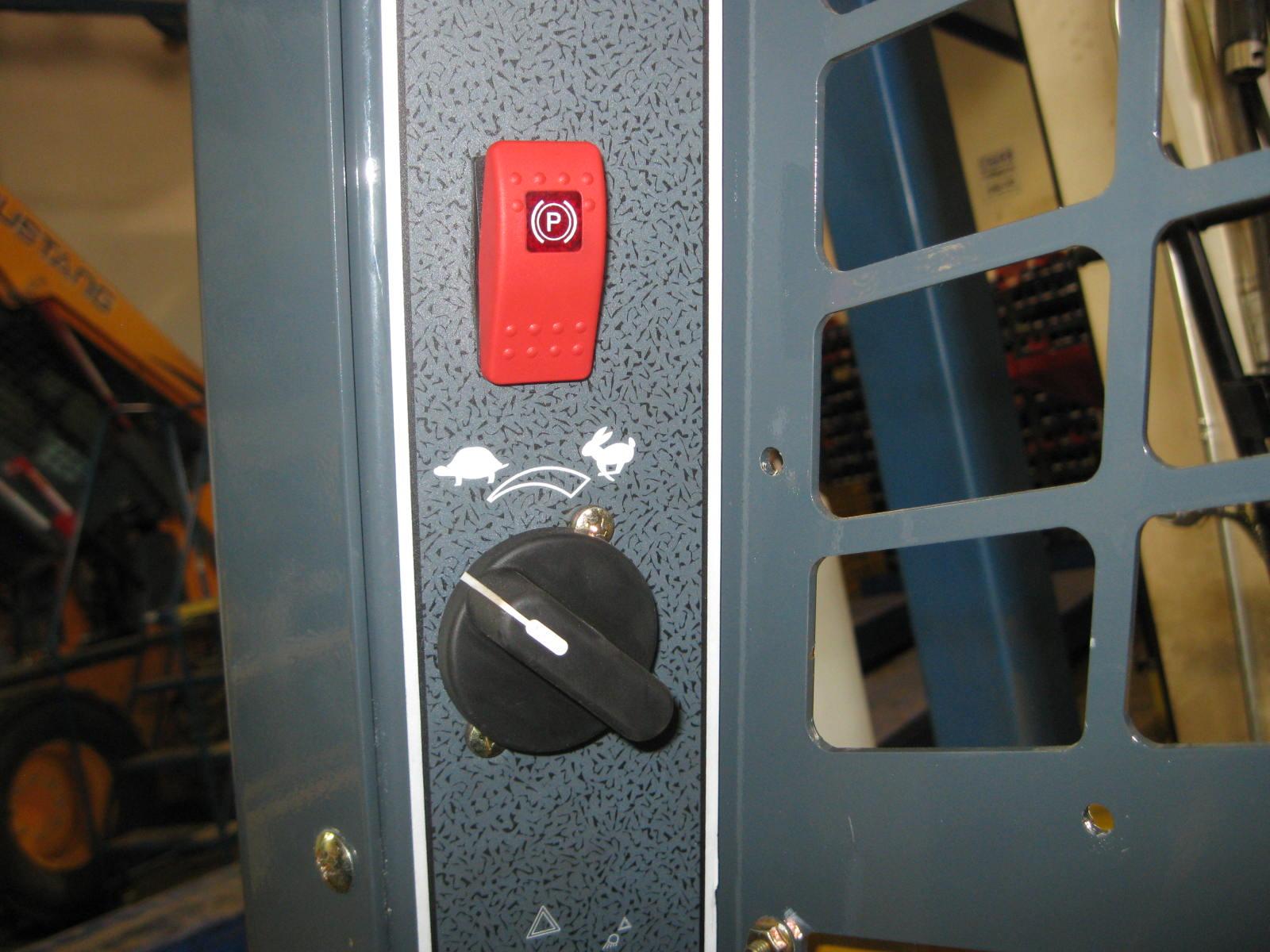
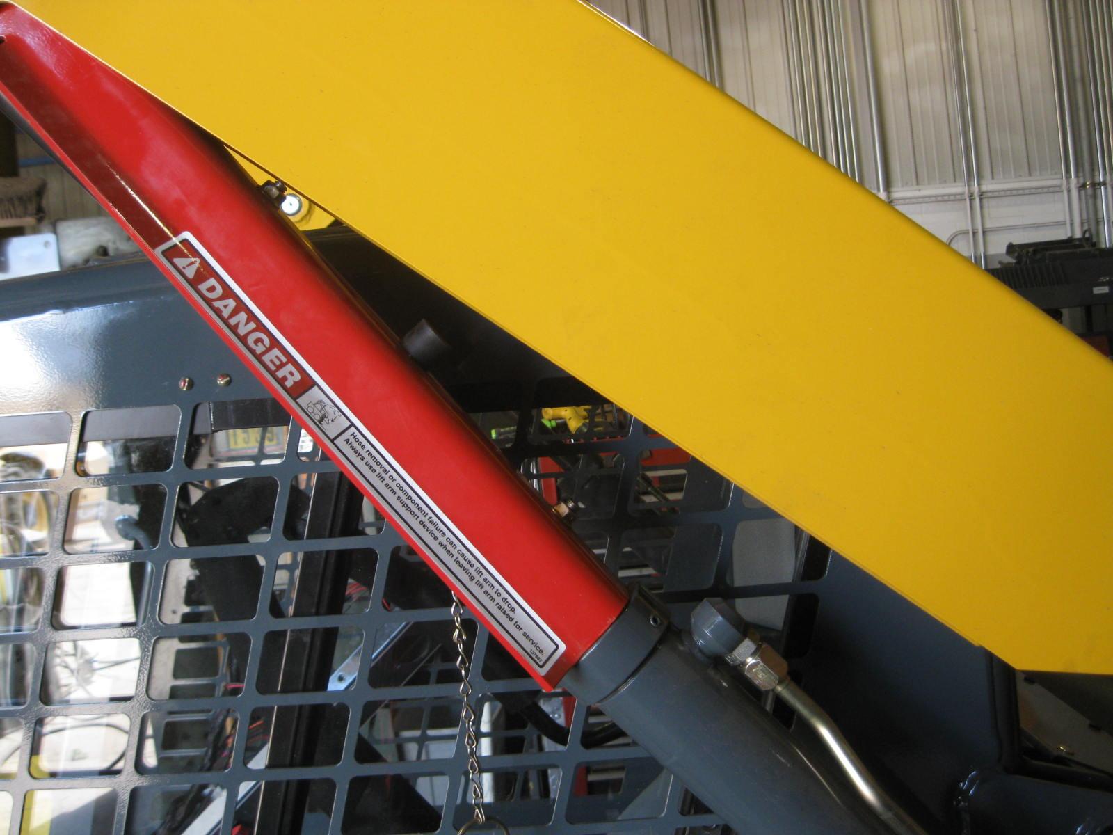
Lift Arm Support Device
The lift arm support device is used as a cylinder lock to prevent the raised lift arm from lowering unexpectedly. Be sure to install the support device when the lift arm is raised for service. When the support device is not being used, return it to its storage position. The support device is a safety device, which must be kept in proper operating condition at all times. The following steps ensure correct usage:
The safest method of engaging the lift arm support device requires two people - one person inside the loader and another person outside the loader to engage the support device.
Note: With the key switch OFF and the solenoid valve working properly, the lift arm will stay raised when the lift control is moved to lower the lift arm. If the valve does not hold the lift am and it begins to lower do not leave the operator’s compartment. Instead, lower the lift arm and exit the machine. Then, contact your Gehl dealer immediately to determine why the lift arm lowers while the key switch is OFF.
Engagement
To engage the lift arm support device:
1.Lower the lift arm fully.
2. Stop the engine.
3. Have an assistant remove the lift arm support device from its storage location (Figure4) on the left side of the machine. Remove the lynch pin holding the support device up against the lift arm. Allow the support device to come down into contact with the lift cylinder (Figure4).
4. Restart the engine.
5. Use the lift control to raise the lift arm until the support device drops over the end of the lift cylinder and around the cylinder rod. Slowly lower the lift arm until the free-end of the support device contacts the top end of the lift cylinder.
6. Look to be sure the support device is secure against the cylinder end. Then, stop the loader engine, remove the key and exit the operator’s compartment.
Disengagement
The safest method of installing and removing the lift arm support device requires two people –one person inside the loader and another person outside the loader to disengage the support device.
Important: With the key switch OFF and the solenoid valve working properly, the lift arm will stay raised when the lift control is moved to lower the lift arm. If the valve does not hold the lift am and it begins to lower do not leave the operator’s compartment. Instead, lower the lift arm and exit the machine. Then, contact your Gehl dealer immediately to determine why the lift arm lowers while the key switch is OFF.
To return the lift arm support device to its storage position:
1.Start the engine.
2. Raise the lift arm fully.
3. Stop the engine.
4. Verify that the lift arm is being held in the raised position by the safety interlock system.
5. To store the support device, have an assistant raise it up until it contacts the lift arm. Reinstall the lynch pin through the welded steel post on the lift arm (Figure5).
Accessory Plug
The 12-V accessory plug is located at the bottom of the right instrument panel.
Dome Light
The dome light is located on the left side of the ROPS/FOPS headliner. Push on the dome light to switch it on.
Work Lights
Loaders have two sets of work lights. The front work lights are located at the top of the ROPS/FOPS. The rear work lights are located at the top of the rear grille.

Heater (optional)
Loaders with the optional heater have two control knobs on top of the heater unit for controlling fan speed and heater temperature.
1. Fan Speed Control Knob: Controls the fan speed and turns the heater system on or off.
2.Temperature Control: The rotary knob regulates the temperature of the heated air. Rotate clockwise to increase the temperature; counterclockwise to decrease the temperature.
Lockable Fuel Cap
Though not necessary to leave locked, the use of a locking fuel cap protects the loader from fuel theft or fuel system vandalism. The key to this lockable fuel cap should be secured to the loader’s key ring. A torque override features aids in the proper installation of the fuel cap. It produces an audible click as the o-ring that seals the cap is properly compressed. To operate the lockable fuel cap:
1.Shut off the engine and remove the key. Insert the fuel cap key into the fuel cap lock.
2. Turn the key 45° clockwise to unlock the fuel cap and turn the cap off the fuel fill neck. When finished fueling the loader, replace the cap and tighten it. Holding the cap, insert the key and turn it 45° counterclockwise to lock the cap in place. Remove the key and check the lock by trying to open the cap.
In the event the key to the lockable fuel cap is lost, contact your dealer or a local locksmith to prevent damage to the cap.
Caution
Engine Speed Control
On DPF Models, an engine speed control (Figure6) is provided for setting the engine speed. Move the control clockwise to increase the engine speed, and counterclockwise to decrease the engine speed. Engine speed may be limited while diagnostic trouble codes (DTC’s) are active or during a cold start. See the engine diagnostic chart for the DTC’s on page73 or the cold starting procedure on page42.
On Non-DPF Models, a right-hand controlled throttle lever is provided on all models for adjusting the engine speed. Move the control forward to increase the engine speed and rearward to decrease the engine speed.
With T-bar controls, a foot pedal (Figure7) is provided as a secondary throttle, which can be used to override the engine speed control. If the foot throttle is released, the engine will return to the speed set by the engine speed control.

Float Control
For hand/foot loaders, use your toes to push the left foot pedal all the way down to detent the float control. For T-Bar loaders push the right control handle fully forward to detent the float control. This mode allows the lowered lift arm to follow the ground contour while traveling over changing ground conditions. For hand/foot loaders, use your heel to push the left foot pedal up to horizontal to deactivate. For T-bar loaders, pull the right control handle rearward to deactivate. The float mode is automatically deactivated when the machine is shut off.
Never use the float mode with the attachment raised, because this will cause the lift arm to lower very rapidly. The float mode can be used where the engine has stopped, is unable to be started, and lowering the lift arm is necessary to allow the operator to exit the loader.