Instrumentation and Indicator Lamps
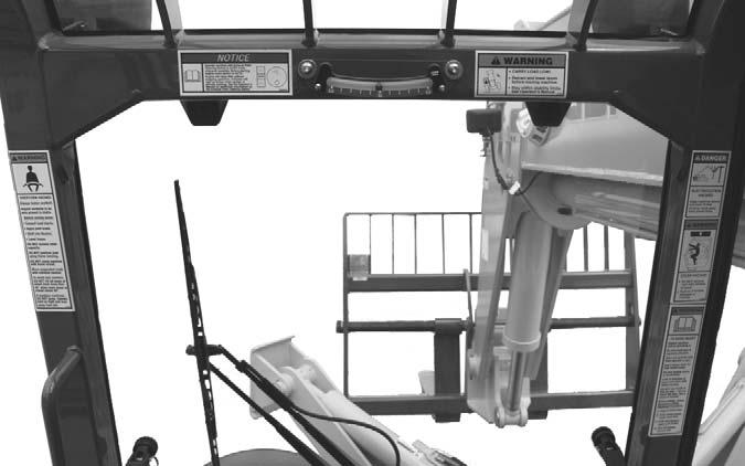
DASH AND STEERING CONSOLE
A
A1
G
C
H
D B
D A2 B
I
E
J
F
K
C
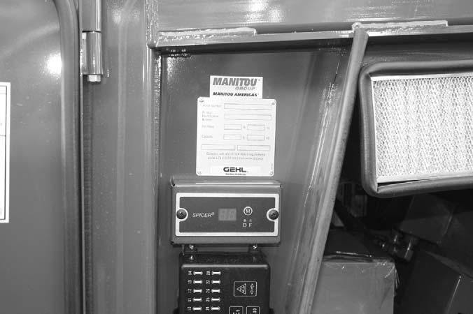
Key Switch, Start Button, Temperature Control and Load Zone Charts
A - Multi-Function Display Screen: This screen displays the following functions:
A1 - Keyswitch OFF: When the key is vertical in the keyswitch, power from the battery is disconnected to the control and instrument panel electrical circuits. This is the only position in which the key can be inserted or removed.
• fuel level at all times, • engine coolant temperature, • engine oil pressure, • voltmeter • hourmeter • 250 hour maintenance reminder • error fault codes B - Scroll Button: Pressing this button changes the function displayed in the multi-function display screen
A2 - Keyswitch ON: When the key is turned one position clockwise from the vertical (OFF) position, power from the battery is supplied to the engine and all control and instrument panel electrical circuits. All indicator lamps in the intrument panel, exhaust filter gauge and switch and the engine emergency override switch will illuminate momentarily as a lamp check.
A1 - Fuel Level Gauge: The fuel level is displayed at all times in the lower portion of the display. It indicates the amount of fuel remaining in the fuel tank.
B - Start Pushbutton: With keyswitch in the ON position, press the start button to activate the starter. Release it as soon as the engine starts.
A2 - Engine Coolant Temperature: Press button “B” until “TEMP” is displayed. It indicates the temperature of the engine coolant. Under normal conditions, this should indicate approximately 185°F (85°C).
NOTE: If the engine requires repeated attempts to start, the key MUST be returned to the OFF position between starting attempts to prevent battery run down.
A3 - Engine Oil Pressure: Press button “B” until “OIL” is displayed. It indicates the engine lubricating oil pressure.
C - Temperature Control Knob: This knob is used to adjust the temperature inside the cab when the heater or air conditioner is in use.
A4 - Voltmeter: Press button “B” until “VOLTS” is displayed. It indicates the voltage output from the alternator.
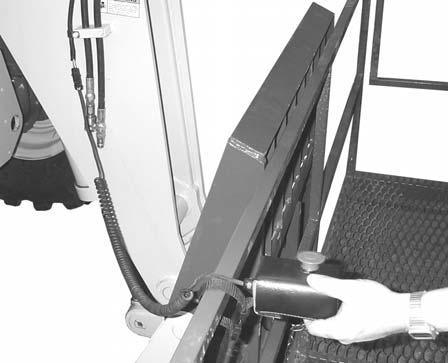
D - Load Zone Charts: A series of flip charts show lift height and reach limits relative to the load weight being handled with various attachment tools.
A5 - Hourmeter: Press button “B” until “HRS” is displayed. It indicates the total operating time of the machine and should be used for keeping the maintenance log. A6 - Maintenance Reminder: After every 250 hours a reminder will display: “ROUTINE MAINTENANCE IS REQUIRED CHECK OPERATOR’S MANUAL.” Perform the required maintenance, and
50960019/DP0115
28
PRINTED IN U.S.A.