41 minute read
Pre-Start Walk-Around Inspection Illustration

from GEHL DL SERIES DL7 DL9 DL11 DL12 Telescopic Handlers Operator’s Manual(50960019D) - PDF DOWNLOAD

PRE-START WALK-AROUND INSPECTION PROCEDURE
Refer to the following illustration and checklist to perform the inspection. Begin with item 1 at the left front of the machine and walk toward the rear of the machine on the left side and around the back and toward the front on the right side of the machine.
Any needed repairs or service noted during the inspection must be performed by a qualified service technician before operating the machine.
The illustration and checklist page can be copied for future pre-start walk-around inspections.
Pre-Start Walk-Around Inspection Checklist
Note the condition of safety decals during the walk-around inspection. Replace missing or illegible safety decals.
o1.Attachment Tool: Check for broken, missing or damaged parts. When using a personnel work platform, check to see if the platform meets ANSI/ITSDF standards and that it is secured to the forks and fork carriage. When using forks, check for welds, cracks or misalignment. Replace the forks in sets when the condition of the forks is questionable.
IMPORTANT: DO NOT use forks that have been repaired by welding.
o2.Attachment Tool Mount: No loose or missing parts; no visible damage.
o3.Attachment Tool Mounting Pins: No visible damage; pin fit is secure and properly lubricated.
o4.Boom Chain: No loose or missing parts; no visible damage; sheave pin fit is secure and lubricated.
o5.Boom Sections and Wear Pads: No loose or missing parts; no visible damage or excessive wear.
NOTE: Wear pads that measure 3/8” (9.5 mm) thick or less need to be replaced.
o6.Outriggers (when equipped): Properly secured; pads in downward position; no visible damage; no loose or missing parts; no leaking from the cylinder.
o7.Boom Angle Indicator: Properly secured; no visible damage; bubble is visible.
o8.Tire and Wheel Assemblies: Properly secured; no loose or missing lug nuts; no visible tire damage (cuts or abrasions); proper inflation.
o9.Front and Rear Axles: No loose or missing parts; no visible damage; tie rod end studs locked; no evidence of leaking; properly lubricated.
o10.Fuel Tank: No visible damage; no evidence of leaking.
o11.Operator Compartment: o Seat belt undamaged; operates properly; mounting hardware secure. o Switches and levers undamage; o no loose or missing parts; o load charts properly secured and legible; o levers and switches operate properly; control markings legible; o frame level indicator secured and undamaged, bubble is visible. o12.Hydraulic Oil Reservoir: No visible damage; no evidence of leaking. o13.Lift Cylinder: Properly secured; no visible damage; no evidence of leaking from the cylinder; properly lubricated. o14.Rear Axle Stabilizer Cylinder: Properly secured; no visible damage; no evidence of leaking from the cylinder; properly lubricated. o15.Slave Cylinder: Properly secured; no visible damage; no evidence of leaking from the cylinder; properly lubricated. o16.Stabilizer Switch and Rod: Properly secured; no visible damage; no loose or disconnected wires. o17.Boom Pivot Assembly: Properly secured; no visible damage or excessive wear; properly lubricated. o18.Boom Hydraulic Hoses: No visible damage or exterior wear; no evidence of leaking. o19.Rear Light Assembly: Properly secured; no visible damage; no loose or disconnected wires; no malfunctions. o20.Hydraulic Control Valve Assembly: No loose or missing parts; no evidence of leaking; no damaged or leaking hoses. o21.Exhaust System: No loose or missing parts; no visible damage; no obstructions to the outlet. o22.Hydraulic Cooler: No loose or missing parts; no visible damage; no evidence of leaking; cleanliness. o23.Engine Compartment: o Engine oil level, add if needed; o Coolant level, add if needed; o No evidence of engine oil or coolant leaks; o Fuel breather cap secure and working; o Hydraulic oil level; breather cap secure and working; o Battery proper electrolyte level; no loose or damaged cables; no visible damage or corrosion; o Belts and hoses in good condition, properly secured and adjusted. o24.Boom Hose Guards: Properly secured; no visible damage. o25.Engine Air Filter (under center cover): No loose or missing parts; no visible damage; no obstructions to the evacuator; pre-cleaner free from dirt. o26.Mirror Assembly: No loose or missing parts; no visible damage; properly adjusted. o27.Cowling and Latches: All cowling, doors and latches in working condition; properly secure; no loose or missing parts; all components operate properly. o28.Frame Tilt Cylinder: Properly secured; no evidence of leaking; properly lubricated. o29.Frame: No visible damage; no cracked welds; no loose or missing parts. o30.Tilt and Auxiliary Hydraulic Hoses: No visible damage or excessive wear; no evidence of leaking. o31.Attachment Tilt Cylinder: Properly secured; no visible damage; no evidence of leaking from the cylinder; properly lubricated.
Date:_________________Initials:_______________
Before Starting Engine
Before mounting the operator’s compartment, walk completely around the machine to be sure no one is under, on, or close to it. Let others in the area know you are going to start up. Wait until everyone is clear of the machine before starting it up.
Before starting the engine and running the machine, refer to the Indicators and Controls chapter and familiarize yourself with the various operating controls, indicators and safety features.
Starting The Engine
Warning
ALWAYS fasten the seat belt BEFORE starting the engine. Leave the park brake applied until the engine is running and you are ready to operate the machine.
The following procedure is recommended for starting the engine in temperatures 32°F (0°C) and above:
1.Grasp the handholds and step up into the operator’s compartment.
2.Adjust the seat and fasten the seatbelt.
3.Check that all controls are in their “neutral” positions, except the parking brake switch, which should be in the “ON” position.
4.Turn the key switch to the “ON” position and press the start button. If the button is released before the engine starts, turn the key switch to the “OFF” position, and allow the starter to stop before attempting to start again.
IMPORTANT: Crank the starter until the engine starts. If the engine fails to start within 30 seconds, return the key to the “OFF” position, wait two minutes, and try again to start the engine. Cranking the engine for longer than 30 seconds will result in premature failure of the starter.
5.After the engine starts, operate the engine at or below 1200 rpm with no load for 1-2 minutes to allow the engine time to warm-up properly before operating the controls.
NOTE: When the parking brake switch is pressed into the “OFF” position, the parking brake will remain applied until the travel lever is placed into either “Forward” or “Reverse.”
6.Check that indicators are in normal condition.
7.Check that there are no fuel, oil or engine coolant leaks, and no abnormal noises or vibrations.
Cold Starting Procedures
The engine is equipped with glow plugs for starting the engine in temperatures down to 0°F (-18°C) and a block heater for starting the engine in temperatures below 0°F (-18°C).
Warning
DO NOT use starting fluid on engines equipped with glow plugs. Ether starting fluid is highly flammable and may explode, causing serious injury.
The following procedure is recommended for starting the engine in temperatures 0°F - 32°F (-18°C - 0°C):
1.Follow steps 1 - 3 as listed in Starting The Engine.
2.Turn the key switch to the “ON” position to activate the glow plugs and wait until the Engine Preheater Indicator light turns off. Then press the start button to start the engine. If the start button is released before the engine starts, turn the key switch “OFF” and repeat the procedure.
NOTE: The glow plugs operate automatically through the ECU. The Engine Preheater Indicator light should always illuminate when the switch is turned ON. In warm weather, the light illuminates briefly as a light check. In cold weather, the light remains on during the automatic operation of the glow plugs. Operating time depends on the temperature. Do not crank the engine until the indicator light turns off.
3.Follow steps 5 -7 as listed in “Starting The Engine”.
The following procedure is recommended for starting the engine in temperatures below 0°F (-18°C):
1.Follow steps 1 - 3 as listed in Starting The Engine.
2.Plug the engine block heater in at least one hour before attempting to start the engine.
3.Turn the key switch to the “ON” position to activate the glow plugs and wait until the Engine Preheater Indicator light turns off. Then press the start button to start the engine. If the start button is released before the engine starts, turn the key switch “OFF” and repeat the procedure.
4.Follow steps 5 -7 as listed in “Starting The Engine”.
Refer to the engine operator manual for additional cold starting procedures.
If the battery becomes discharged and has insufficient power to start the engine, jumper cables can be used for starting assistance. Refer to the jump starting instructions in the Service and Storage chapter of this manual for safe jump starting procedures.
Stopping
The following procedure is the recommended sequence for stopping the machine:
1.Bring the machine to a stop on a level surface. Avoid parking on a slope, but if necessary park across the slope and block the wheels.
2.Fully retract the boom and lower the attachment to the ground.
3.Idle the engine for at least 2 minutes for gradual cooling.
IMPORTANT: If an Exhaust Filter Cleaning has just been performed, increase the engine idle time to 4 minutes.
4.Place controls in neutral. Apply the parking brake.
5.Turn the ignition switch key to the “OFF” position. Remove the key.
6.Unfasten the seatbelt, and grasp the handholds while climbing out of the operator’s compartment.
First Time Operation
Make sure the engine is warm and then go through the following procedures:
Caution
Be sure the area being used for test-running is clear of spectators and obstructions. Initially, operate the machine with an empty attachment tool.
Place the travel lever in a speed range and in Forward or Reverse. Turn off the parking brake switch and move slowly, while testing the steering and brakes. Stop and operate all boom functions and frame leveling controls, checking for smooth responses.
Apply the service brakes, and move the travel lever to the opposite direction (forward or reverse).
Shifting to the next higher gear may be done at any engine speed while the machine is in motion.
DO NOT overspeed the engine when down shifting. Allow the machine to slow down before shifting to the next lower gear.
Engine Shutdown Protection
The engine is equipped with a WARNING and SHUTDOWN feature that warns users of low engine oil pressure and of high engine coolant temperature. If the problem is not corrected, the engine power will be reduced automatically, or the engine will shut down.
Engine Oil Pressure
There are two low oil pressure protection features: Low Oil Pressure WARNING, and Low Oil Pressure SHUTDOWN.
At the Low Oil Pressure WARNING set-point, the warning lamp in the engine override switch and the amber lamp in the exhaust filter gauge will flash, and a slow engine power derate will begin. But if the oil pressure rises above the Low Oil Pressure WARNING set-point, power will slowly increase until the engine is back to full power. The lamp in the switch and exhaust filter gauge will continue to flash until the power has returned to normal, even if the fault condition has been corrected and the recovery is in process.
At the Low Oil Pressure SHUTDOWN set-point, the lamp in the engine override switch and the amber lamp in the exhaust filter gauge will light continously, and a fast engine power derate will begin. If the oil pressure does not rise above the SHUTDOWN set-point within 30 seconds, the engine will shut down. However, if the oil pressure rises above the Low Oil Pressure SHUTDOWN set-point within 30 seconds, then the power derate speed will revert to the Low Oil Pressure WARNING speed of reaction.
Engine Coolant Temperature
There are two coolant temperature protection features: High Coolant Temperature WARNING, and High Coolant Temperature SHUTDOWN.
At the High Coolant Temperature WARNING setpoint, the warning lamp in the engine override switch and the amber lamp in the exhaust filter gauge will flash and a slow engine power derate will begin. But if the coolant temperature drops below the High Coolant Temperature WARNING set-point, the power will increase slowly until the engine is back to full power. The lamp in the switch and exhaust filter gauge will continue to flash until the power has returned to normal even if the fault condition has been corrected and the recovery is in process.
At the High Coolant Temperature SHUTDOWN setpoint, the lamp in the engine override switch and the amber lamp in the exhaust filter gauge will light continously, and a fast engine power derate will begin. If the coolant temperature does not drop below the SHUTDOWN set-point within 30 seconds, the engine will shut down. However, if the coolant temperature drops below the High Coolant Temperature SHUTDOWN set-point within 30 seconds, then the power derate speed will revert to the High Coolant Temperature WARNING speed of reaction.
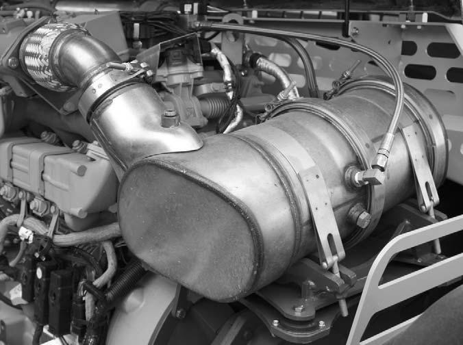
Exhaust Filter Cleaning System
The engine is equipped with an exhaust filter in place of a muffler. This filter is located to the front of the engine under the engine cover. This exhaust filter reduces carbon monoxide, hydrocarbons, and particulate matter from the exhaust stream. Trapped particles are eventually oxidized through a process known as regeneration or exhaust filter cleaning.
Under normal machine operation and with the system in AUTO mode, the exhaust filter requires minimal operator interaction.
To avoid unnecessary buildup of diesel particles or soot in the exhaust filter system;
1.Utilize the Automatic (AUTO) Exhaust Filter Cleaning mode.
2.Avoid unnecessary idling.
3.Use the proper engine oil. See Lubrication chapter of this manual or the engine manual for proper engine oil specifications.
4.Use only ultra low sulfur diesel (ULSD) fuel. See Lubrication chapter of this manual or the engine manual for fuel requirements.
Even with proper maintenance, ash and soot will build up in the exhaust filter after several thousand hours of operation and require service. This service will need to be performed by a authorized Gehl dealer.
Automatic (AUTO) Exhaust Filter Cleaning
Operating the engine in AUTO Mode allows the ECU to perform intelligent exhaust cleaning as required. The Exhaust Filter Cleaning Indicator will illuminate when the system is actively performing an exhaust filter cleaning. When the exhaust filter cleaning process has completed its cycle, the cleaning indicator will turn off.
The machine can be operated as normal during the auto exhaust filter cleaning process unless the operator determines the machine is not in a safe location for high exhaust temperatures and disables the auto cleaning process.
To enable the auto exhaust filter cleaning mode, the exhaust filter cleaning rocker switch should be in the center position.
IMPORTANT: It is recommended that the exhaust filter cleaning be in the Auto mode at all times. Auto mode should only be disabled when the machine is not in a safe location during the exhaust filter cleaning process.
If the machine is not able to be moved to a safe location, the operator should temporarily disable auto exhaust filter cleaning. If the machine is located in a safe location, the auto mode should always be enabled.
Manual/Parked Exhaust Filter Cleaning
Manual/Parked exhaust filter cleaning is initiated by the operator. This process allows the system to clean the exhaust filter when the operator previously needed to disable the auto exhaust cleaning process because of specific conditions. During this process the engine speed will be controlled by the ECU. The machine must remain parked to during this process.
Warning
During auto or manual exhaust filter cleaning operations, the engine will run at elevated idle and hot temperatures for approximately 30 minutes. Exhaust gases and exhaust filter components reach temperatures hot enough to burn people, ignite, or melt common materials.
Servicing the machine or attachments during exhaust filter cleaning can result in serious personal injury. Avoid exposure and skin contact with hot exhaust gases and components.
If the machine is note in a safe location for elevated temperatures, move the machine to a safe location and check for adequate fuel level before beginning the exhaust filter cleaning process.
NOTE: It is not necessary to perform a manual/parked exhaust cleaning unless a previous auto cleaning process was cancelled and the indicator in the exhaust filter gauge is illuminated.
Cleaning times will vary depending upon several specific criteria. The average standard cleaning time can range from 20 - 50 minutes or longer.
To enable manual/parked exhaust filter cleaning;
1.Park the machine in a safe location and check that the machine has a recommended 1/4 tank of fuel to complete the process.
2.Reduce engine speed to low idle and apply the parking brake.
3.Press the top of the exhaust filter cleaning switch for approximately 3 seconds until the indicator in the switch illuminates. The cleaning indicator in the exhaust filter gauge will also illuminate.
The indicators will go off when the exhaust filter cleaning process is completed. If the machine is not going to be returned to service immediately after the cleaning process, allow the engine and the exhaust filter time to return to normal operating temperature before stopping the engine. The manual/parked filter cleaning process can be canceled at any time during the process.
Avoid disabling the cleaning process unless absolutely necessary. Repeated disabling or ignoring prompts to perform a manual/parked cleaning procedure will cause additional engine power limitations and can eventually lead to a “Service Only” soot condition.
Utilize AUTO Exhaust Filter Cleaning mode to avoid additional service.
Disable Exhaust Filter Cleaning
Disabling the exhaust filter cleaning request is not recommended. Disable the automatic exhaust filter cleaning only when necessary. Whenever possible, cleaning should be allowed and the exhaust filter cleaning switch should be left in the AUTO Mode. When left in auto mode, soot buildup in the exhaust filter system will be at a minimum.
To disable exhaust filter cleaning, press the bottom of the exhaust filter cleaning rocker switch. The Auto Cleaning Disabled Indicator located in the exhaust filter gauge will be illuminated.
Exhaust Filter Cleaning Precautions
When the AUTO Exhaust Filter Cleaning is disabled, the system has 3 levels of notification to advise the operator to perform the exhaust filter cleaning. The 3 levels are as follows;
1.The Exhaust Filter Indicator will illuminate, indicating the soot level in the filter is slightly high. If conditions are safe, the operator should enable auto exhaust filter cleaning or perform a manual exhaust filter cleaning.

2.The Exhaust Filter Indicator and the Amber Alert Indicator in the exhaust filter gauge will illuminate. The engine performance will be reduced by the ECU because the soot level in the exhaust filter is moderately high.

If conditions are safe, the operator should enable auto exhaust filter cleaning. If conditions are not safe, the operator should move the machine to a safe location and either enable the auto exhaust filter cleaning or perform a manual exhaust filter cleaning.
3.The Exhaust Filter Indicator and the Red Alert Indicator in the exhaust filter gauge will illuminate. The ECU will further reduce engine performance. Continuing to operate the machine at this level will set a “Service Only” soot condition where the engine cannot clean the exhaust filter itself. In this condition, perform a Manual/Parked Exhaust Filter Cleaning. A “Service Only” exhaust cleaning time can range from 3 - 4 hours.
IMPORTANT: Be sure the machine is parked in a safe place and has an adequate amount of fuel to complete a 3 - 4 hour exhaust filter cleaning.
Parking Brake
NOTE: The parking brake mechanism within the front axle is not designed for, and not intended to be used as, the primary means of stopping movement of the machine. Hydraulic braking provided through the service brakes within the axle is the primary means for stopping movement.
The proper sequence for correct machine operation is to always engage the parking brake switch before shutting off the engine, and to disengage the brake ONLY after the engine is running. In an emergency however, if it becomes necessary to stop movement, activate the parking brake switch to “ON.”
Changing Attachment Tools
The Telescopic Handler boom nose will accept two types of Gehl attachment devices: 1.) Dynattach® quick-attach system, which has a quick-release hookup and locking mechanism for mounting framing and masonry type attachment tools to the boom nose, and 2.) Dynacarrier® quick-attach system, which has a quick-release locking mechanism that uses a single lock lever control for attaching and detaching materialhandling type attachment tools.
Dynattach® System Attaching Procedure
To pick up an attachment tool, proceed as follows:
1.Raise the boom slightly and extend it 2 or 3 feet (600 to 900 mm) for better visibility. Tilt the tool carrier forward.
2.Align the tool carrier squarely with the back of the attachment tool.
3.Slowly extend the tool carrier and lower the hooks under the attachment tool hookup bar.
4.Tilt the tool carrier back so that the lock plate engages the attachment tool. This secures the attachment tool to the Dynattach System.
5.For an attachment tool with auxiliary hydraulics, connect hoses to the quick-connect connectors on the boom nose.
Dynattach® System Detaching Prodedure
To detach the attachment tool, proceed as follows:
1.Raise the boom slightly and extend it 2 or 3 feet (600 to 900 mm) for better visibility. Lower the boom until the attachment tool is approximately 12” (300 mm) off the ground.
2.Roll back the carrier as far as it will go. When the carrier is rolled back completely, perform the MANDATORY SAFETY SHUTDOWN PROCEDURE (Safety chapter, p. 9).
3.With the engine off, leave the operator’s station and manually raise the lock spring and flip the lock plate up and outward at least 180° so that it is in position to re-lock onto the next attachment tool.
4.Tilt the tool carrier forward to allow the attachment tool to roll out, then lower the boom so that the hook ears clear the hookup bar on the attachment tool.
NOTE: One side of the lock plate has a bright red decal to indicate the unlocked position.
5.If the attachment tool has auxiliary hydraulics, disconnect the hoses from the quick-disconnects on the boom nose.
6.Start the engine and roll the tool carrier forward. Slowly back the machine until the attachment tool is free from the boom nose.
Attaching Manual Dynacarrier ® Quickattach System
To pick up a bucket or material handling carriage tool, proceed as follows:
1.Rotate the lock lever completely to the left (counter-clockwise, as viewed from the operator’s station) to fully retract the lock pins.
2.Raise the boom slightly and extend it 2 or 3 feet (600 to 900 mm) for better visibility. Tilt the tool carrier forward.
3.Align the tool carrier squarely with the back of the attachment tool.
4.Slowly extend the tool carrier and tilt it forward until the support pins on each side are in-line with and slightly below the hookup ears on the back side of the attachment tool.
5.Slowly drive the machine forward, and, at the same time, roll the tool carrier back to engage the hookup ears on the attachment tool. Also, establish proper alignment of the carrier lock pins to the attachment tool.
6.Stop forward travel when the hookup ears are engaged, but continue to roll the tool carrier back to pick the attachment tool off the ground. When the tool carrier is rolled back completely, perform the MANDATORY SAFETY SHUTDOWN PROCEDURE (Safety chapter, p.9).
7.With the engine off, leave the operator’s station, and swing the lock lever completely to the right (clockwise, as viewed from the operator’s station) to fully engage the lock pins.
Warning
To prevent unexpected and undesired attachment tool release from the boom carrier, be sure to properly secure the quick-release lock pins by rotating the lock lever all the way to the right or inside.
Modifications, alterations to, or use of attachment tools not authorized by Gehl Company can void the warranty and cause machine damage, and may result in serious personal injury or death.
8.For an attachment tool with auxiliary hydraulics, connect the hoses to the quick-connect connectors on the boom nose.
Detaching Manual Dynacarrier® Quickattach System
To detach the attachment tool, proceed as follows:
1.Raise the boom slightly and extend it 2 or 3 feet (600 to 900 mm) for better visibility. Lower the boom until the attachment tool is approximately 12” (300 mm) off the ground.
2.Roll back the tool carrier as far as it will go. When the tool carrier is rolled back completely, perform the MANDATORY SAFETY SHUTDOWN PROCEDURE (Safety chapter, p. 9).
3.With the engine off, leave the operator’s station, and rotate the lock lever completely to the left (counter-clockwise, as viewed from the operator’s station) to fully retract the lock pins.
4.If the attachment tool has auxiliary hydraulics, disconnect the hoses from the quick-connects on the boom nose.
5.Start the engine and tilt the tool carrier forward. Slowly back the machine until the attachment tool is free from the boom carrier.
Attaching Hydraulic-Actuated Dynacarrier® Quick-attach System
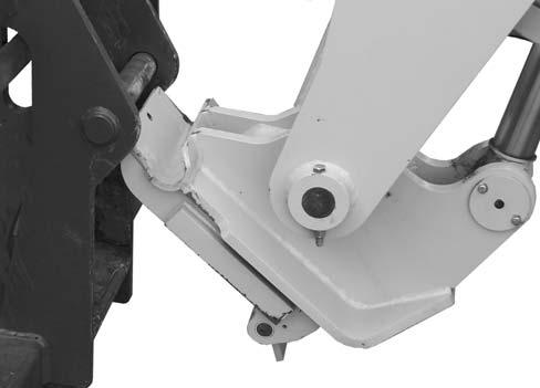
1.With the engine off, leave the operator’s station, and turn the circuit selector handle on the end of the boom 1/4 turn counter-clockwise to the Attachment Lock Pins position.
and slightly below the hookup ears on the back side of the attachment tool.
5.Slowly drive the machine forward, and, at the same time: a.On machines with a four-button joystick, press and hold the lower blue auxiliary hydraulic button to retract the attachment lock pins. b.On machines with a two-button joystick, press and hold the blue button on the joystick handle and then move the handle rearward to retract the attachment lock pins.
Roll the tool carrier back to engage the hookup ears on the attachment tool.
6.Stop forward travel when the hookup ears are engaged, but continue to roll the tool carrier back to pick the attachment tool off the ground. When the tool carrier is rolled back completely: a.On machines with a four-button joystick, release the lower blue auxiliary hydraulic button and press the upper blue auxiliary hydraulic button to engage the attachment lock pins. b.On machines with a two-button joystick, press and hold the blue button on the joystick handle and then move the handle forward to engage the attachment lock pins.
Perform the MANDATORY SAFETY SHUTDOWN PROCEDURE (Safety chapter, p. 9).
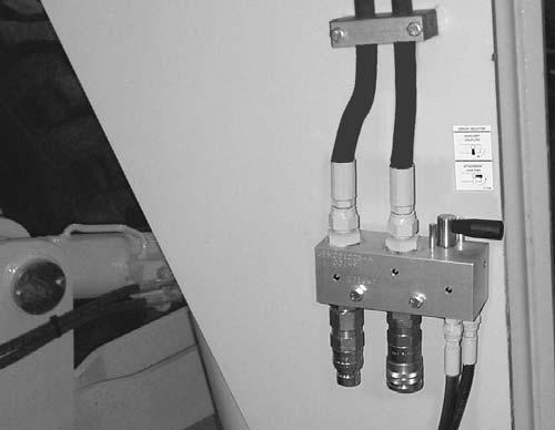
Circuit Selector Handle
2.Raise the boom slightly and extend it 2 to 3 feet (600 - 900 mm) for better visibility and tilt the tool carrier forward.
3.Align the tool carrier squarely with the back of the attachment tool.
4.Slowly extend the tool carrier and tilt it forward until the support pins on each side are in-line with
7.With the engine off, leave the operator’s station, and turn the circuit selector handle on the end of the boom 1/4 turn clockwise to the Auxiliary Couplers position.
Warning
To prevent unexpected and undesired attachment tool release from the Dynacarrier ® Quick-attach, be sure to turn the Circuit Selector Handle to the Auxiliary Couplers position after the lock pins are engaged to the attachment tool.
Modifications, alterations to, or use of attachment tools not authorized by Gehl Company can void the warranty and cause machine damage, and may result in serious personal injury or death.
8.For an attachment tool with auxiliary hydraulics, connect the hoses to the quick-connect connectors on the boom nose.
Detaching Hydraulic-Actuated Dynacarrier®Quick-attach System
To detach the attachment tool, proceed as follows: a.On machines with a four-button joystick, press and hold the lower blue auxiliary hydraulic button to retract the attachment lock pins, tilt the tool carrier forward. b.On machines with a two-button joystick, press and hold the blue button on the joystick handle and then move the handle rearward to retract the attachment lock pins, tilt the tool carrier forward.
1.With the engine off, leave the operator’s station, and, if the attachment tool has auxiliary hydraulics, disconnect the hoses from the quickconnects on the boom nose .
2.Turn the circuit selector handle on the end of the boom 1/4 turn counter-clockwise to the Attachment Lock Pins position.
3.While sitting in the operator’s seat, start the engine and raise the boom slightly and extend it 2 to 3 feet (600 - 900 mm) for better visibility. Lower the boom until the attachment tool is approximately 12” (300 mm) off the ground.
4.Slowly back the machine until the attachment tool is free from the tool carrier. With the joystick to the neutral position, release the blue button.
SELF-LEVELING
The machine has a hydraulic self-leveling feature. This feature is designed to keep the attachment tool level while the boom is being raised.
Machine Operation With Solid Rubber Tires
Solid rubber tires are designed for intermittent service and limited running distances. The Working Day Average Speed should not exceed 3 mph at an average load of 75% of maximum capacity. Telehandlers equipped with solid rubber tires should not be used in applications requiring speeds over 15 mph, or continuous journeys over 1 mile when loaded at or above 50% of capacity. In the event an application requires vehicle speeds over 15 mph, excessive roading, or driving extended distances while loaded, Gehl recommends the use of other approved tire options.
Warning
The DL12-55 telehandler must be equipped with foam filled or solid rubber tires for proper load capacity and stability.
Use of pneumatic tires will not provided published rated capacity or stability as shown on the load chart and may contribute to a tip over resulting in death, serious injury or property damage.
General Machine Operation
Check the Telescopic Handler to be sure all systems are in good operating condition. Perform the following steps before starting the machine for the first time each day.
Warning
Exhaust fumes can kill. Ensure proper ventilation when starting indoors or in enclosed areas.
Use proper grab handles, NOT the steering wheel or control levers as handholds when mounting or dismounting.
NEVER operate the machine with safety guards or covers removed.
Over-inflated tires can explode and cause injury or death. Tire repairs MUST be made only by authorized personnel using proper tools and equipment.
1.Check the engine oil, coolant, transmission oil and hydraulic oil levels.
2.Make sure weekly lubrication has been done.
3.Visually inspect for leaks, broken or malfunctioning parts. Make sure all caps, covers and safety shields are in place.
4.Check tires for cuts, bulges, nails, correct pressure, loose wheel nuts, etc.
5.Inspect the work area. Make sure you know where you will make load pickups, lifts, and turns. Look over the terrain of the jobsite for holes, obstacles, slippery surfaces, soft or deep mud.
6.Check clearances of ramps, doorways and passage ways. Check overhead clearances if you will travel and place loads near power or telephone lines.
If the machine is found to be in need of repair or in any way unsafe, or contributes to an unsafe condition, the matter shall be reported immediately to the user’s designated authority. The machine must NOT be operated until it has been restored to a safe operating condition. Operate the travel controls gradually and smoothly when starting, stopping, turning and reversing the directions.
Grade and Slope Precautions
The Telescopic Handler complies with industry stability tests requirements and is stable when properly operated. However, improper operation, faulty maintenance, or poor housekeeping may contribute to a condition of instability and defeat the purpose of the standard.
The amount of forward and rearward tilt to be used is governed by the application. Although use of maximum rearward tilt is allowable under certain conditions, such as traveling with the load fully lowered, the stability of the machine, as determined by the industry standard tests, does not encompass consideration for excessive tilt at high elevations, or the handling of offcenter loads.
Handle only loads within the capacity limits of the machine, and that are stable and safely arranged. When attachments are used, extra care should be taken in securing, manipulating, positioning and transporting the load.
Grade Limits
NOTE: Grade limits are based on ANSI/ITSDF standard B56.6-2005.
The telescopic handler meets or exceeds the safety standard (ANSI/ITSDF B56.6) stability limits for rough-terrain forklifts. The stability tipping limits cover specific, controlled test conditions, which are extremes, and which are not intended to be achieved during normal worksite operations. The following specifications are provided only as information to the operator, and must not be used as a guideline for operating the telescopic handler. For safe operation, always follow the instructions and warnings provided in this manual.
Warning
DO NOT level the frame with the boom raised or extended. Level the frame ONLY while stopped, with the boom fully retracted, and the attachment tool raised just enough to clear the ground.
1.DO NOT place or retrieve loads on a up or down slope or grade that exceeds 7% or 4o grade.
2.DO NOT travel up or down a grade or slope that exceeds 22% or 12o grade while loaded.
3.DO NOT place or retrieve loads on a side hill with a slope or grade that exceeds 12% or 7o grade. Regardless of the terrain or position of the wheels, the FRAME MUST BE LEVEL, as indicated by the frame angle indicator on the ROPS crossmember.
4.DO NOT travel across a side hill that exceeds 18% or 10o grade. Regardless of the terrain or position of the wheels, the FRAME MUST BE LEVEL, as indicated by the frame angle indicator on the ROPS crossmember. The attachment tool MUST be maintained at the “carry” position, with the boom fully retracted, and attachment tool at minimum ground clearance.
When ascending or descending grades in excess of 5% or 3o, the machine should be driven with the load upgrade. An unloaded machine should be operated on all forward grades with the load handling attachment tool downgrade, tilted back if applicable, and raised only as far as necessary to clear the road surface. Avoid turning if possible and use extreme caution on grades, ramps or inclines. Normally travel straight up and down.
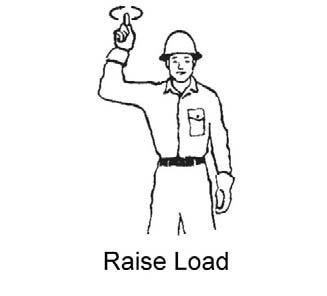
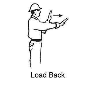
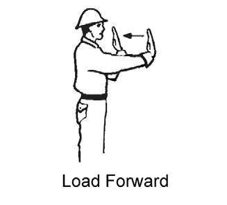
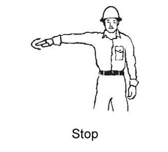
Traffic Flow Patterns
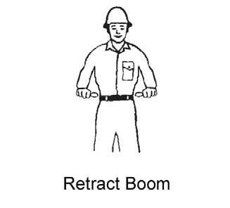
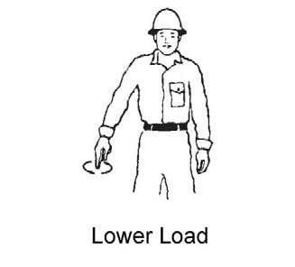
For safety, know and understand the traffic flow patterns of your jobsite and the Telescopic Handler hand signals. Use signal persons and make sure you can see the signal person and acknowledge the signals given. Refer to the safety hand signal illustrations on the next page.
The backup alarm automatically sounds when the travel lever is in Reverse. Care should be taken when down shifting or reversing because damage to the transmission can occur if shifting is forced or attempted while traveling.
When ramps must be used in transporting loads with the machine, the following shall be the minimum widths for safe travel:
Compacted dirt, gravel, etc. - 12 ft. (3.6 m) Woodboard, concrete, etc. - 10 ft. (3 m)
Permanent aisles, roadways, passageways, floors and ramps should be marked or defined in some fashion. Permanent or temporary protrusion of loads, equipment, material and construction facilities into the usual operating area should be guarded, clearly and distinctively marked, or clearly visible.
Maintain a safe distance from the edge of ramps, platforms and other similar working surfaces.
Controlled lighting of adequate intensity should be provided in operating areas. Where operating conditions indicate, the operator/user is responsible for having the machine equipped with lights.
Provision should be made to prevent trucks, semi-trailers and railroad cars from being moved during loading and unloading. Wheel stops, parking brakes, or other positive means should be used to prevent movement during loading and unloading.
DO NOT move railroad cars or trailers with the Telescopic Handler.


DO NOT use the boom and attachment for leverage to push the machine out of mud.
IMPORTANT: DO NOT lower boom at high engine speed when attachment tool is at maximum rearward tilt. Damage to slave cylinders may result.

General Load Handling
NEVER attempt to work controls except from the operator’s seat. NEVER jerk or use fast movements. Avoid sudden stops, starts and changes in direction.

Warning
Excessive speed can be hazardous. ALWAYS exercise caution and good judgement while operating the machine.
The Mandatory Work Platform Safety Rules must be adhered to at all times while elevating personnel.
ALWAYS maintain a safe distance from electric power lines and avoid contact with any electrically charged conductor and gas line. It is not necessary to make direct contact with a power line for power to ground through the structure of the machine. Keep the boom and load at least 10 ft. (3 m) from all power lines. Accidental contact or rupture can result in electrocution or an explosion. Contact the “Call Before You Dig” referral system number at 8-1-1 in the U.S., or (888) 258-0808 in the U.S. and Canada, to locate any underground utility lines BEFORE starting to dig.
Keep all body parts inside the operator’s station while operating the machine. BE SURE of clearance for the attachment tool when turning, working around buildings, etc.
Turning corners too fast can tip the machine, or cause a load to tip off the attachment. Sudden slowing or stopping of the machine may cause the load to fall off the attachment tool.
Be certain you can control both speed and direction before moving. Always place the machine in neutral and set the parking brake before raising or extending the boom. NEVER drive the machine up to someone standing in front of the load.
NEVER leave the operator’s station without first lowering the attachment tool to the ground. Set the parking brake, place controls in neutral, shut off engine and remove the key. AVOID parking the machine on a slope, but if necessary, park across the slope and block the tires.
Operation of the hydraulic system depends on engine speed and the distance the controls are moved. When operating these controls it is important to develop a technique called “feathering.” Feathering the control means starting the desired motion by moving the control a small amount away from neutral. Then, after movement has started, the control can be eased to full movement. Use the same feathering technique to stop the motion.
Load Capacity and Reach
The machine has flip-charts in the operator’s station that provide, at a glance, the capacity limits at various positions of attachment tool extension and elevation. A set of the load zone charts is reproduced at the end of this manual for reference.
A typical load zone chart is shown on the next page. The scale on the left indicates height in feet above the ground level. The scale on the bottom shows the distance in feet from the front of the machine. The arc lines noted by the numbers “1” through “5” correspond with the position extension markers on the operator side of the intermediate boom section.
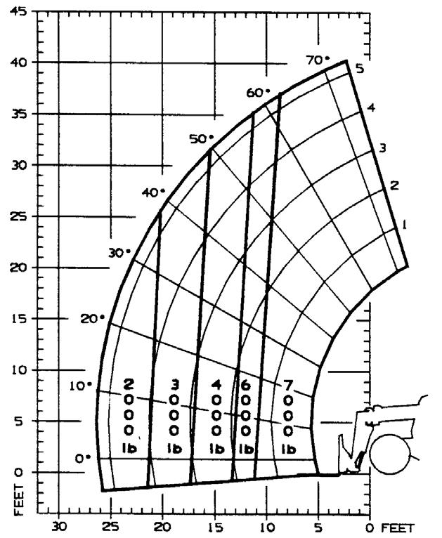
The following example illustrates proper use of the load zone charts for the Telescopic Handler:
Example: The operator, using a standard carriage attachment tool without outriggers, wants to raise a 3000 lb. load 20 feet high, and can only get to within 15 feet of the load placement point. Can this be done within the capacity of the machine?
Analysis: See “Typical Load Zone Chart”.
Projecting up from the 15-foot reach mark on the horizontal axis to intersect a line through the 20-foot height mark on the vertical axis shows that up to a 4000 lb. load can be placed in that zone.
During placement, the operator should observe when the arc reference number “4” on the boom is visible and stop. The operator knows the maximum safe extension distance with the 4000 lb. load has been reached.
Warning
NEVER exceed the rated operating capacity of the Telescopic Handler as shown on the load zone charts.
HANDLING NON-SUSPENDED LOADS
Picking Up the Load
Inspect the load. If it appears unstable, DO NOT attempt to move it. DO NOT attempt lifting doubletiered loads, or straddling side-by-side pallets with one on each fork. NEVER add extra unauthorized counterweights to this machine. Consider the additional weight of any attachment tool as part of the picking load capacity of the machine.
Warning
Operating conditions such as slopes or soft ground can reduce the machines safe operating capacity. Exceeding the capacity when raising or extending the boom will cause the machine to tip forward.
Approach the load slowly and squarely with the machine straight and level. Adjust the space between forks, if necessary. Engage the load equally on both forks until the load touches the carriage backrest. Tilt the forks back to position the load for travel.
Carrying the Load
If the load obstructs your view, get someone to direct you. Maintain ground speeds consistent with ground conditions and that permit stopping in a safe manner.
Warning
NEVER travel with the boom above the carry position (attachment tool should be at minimum ground clearance). Boom should be fully retracted.
Use lower gears when traveling down an incline. NEVER coast with the transmission in neutral. Travel up and down grades slowly.
DO NOT operate the machine on a slope or grade that exceeds 22% or 12o.
Load Elevation and Placement
For ground level load placement, be sure the area under the load and around the machine is clear of equipment and personnel. Lower the load to the ground, tilt the forks to the horizontal position, and then carefully back away to disengage the forks from the load.
For elevated or overhead placement, bring the machine as close as possible to the landing point, and then:
1.Level the machine BEFORE raising the load. Use extreme caution for high placement. Be sure personnel are clear of the area where the load or the machine could fall or tip.
2.Set the parking brake, shift the transmission into neutral, hold the service brake pedal fully applied and slowly raise the load, maintaining a slight rearward tilt to cradle the load.
3.As the load approaches the desired height, feather the boom control at minimum speed until the load is slightly higher than the landing point.
4.Continuing the feathering technique, lower the load into place.
5.Free the forks from the load by alternately retracting and raising the boom. If this process is not possible, very slowly and carefully reverse the telescopic handler to free the forks from the load.
6.Lower the forks to travel height.
Handling Suspended Loads
Determine the weight and load center of the load to be handled. Refer to the telehandlerload chart to determine if the load can safely be handled.
NOTE: Refer to the standard carriage load chart when using the boom mounted hook.
Warning
NEVER exceed the rated operating capacity of the telehandler as shown on the load zone charts.
Warning
Operating conditions can reduce the telehandler’s safe operating capacity. Exceeding the capacity when raising or extending the boom will cause the telehandler to tip forward.
Picking Up Suspended Load
1.Rigging should be in good condition and rated for the load being lifted.
2.Rigging should comply with OSHA regulation §1910.184, “Slings,” or §1926.251, “Rigging equipment for material handling.”
3.Be sure the rigging equipment is clear of any part of the machine or machine attachment before lifting the load.
4.Avoid lifting double-tiered or any unstable loads.
5.Only lift loads vertically and clear from any adjacent obstacles. Never drag the load horizontally.
6.Use multiple lift points and taglines to restrain the load from swinging or rotating.
Carrying Suspended Load
3.All telehandler movements should be performed slowly and cautiously to prevent load swing. Avoid abrupt movement. Do not exceed walking speed.
4.Use a signal person anytime the load restricts the operators view or assistance is required. The signal person should remain in contact (verbally or visually) with the operator at all times until the load is placed.
Ground Level Suspended Load Placement
1.Be sure the area under the load and around the telehandler is clear of equipment and personnel.
2.Lower the load to the ground till load is stationary and the rigging is loose from the load. Have signal person disconnect the rigging from the load.
3.Raise boom enough to clear the rigging from the load before backing the telehandler away from the load.
Elevated Suspended Load Placement
1.Bring the telehandler as close as possible to the landing point.
2.Level the telehandler BEFORE raising the load. Use extreme caution for high placement. Be sure personnel are clear of the load landing area.
3.Set the parking brake, shift the transmission into neutral, hold the service brake pedal fully applied and slowly raise the load.
4.As the load approaches the landing point, feather the boom control at minimum speed until the load is just above the landing point.
5.With the assistance of a signal person, continue the feathering technique to lower the load into place.
Warning
NEVER place the signal person between the load and the telehandler or other stationary objects.
1.Rigging between the load and attachment should be as short as possible to reduce boom height.
2.Do not raise the load more than 12 inches (305 mm) above the ground or raise the boom more than 45 degrees.
6.Once the load is stationary on the landing point and the rigging is loose from the load, have the signal person disconnect the rigging from the load.
7.Raise boom enough to clear the rigging from the load. Slowly and carefully, reverse the telehandler till the rigging is clear of the load.
8.Lower the boom to travel height.
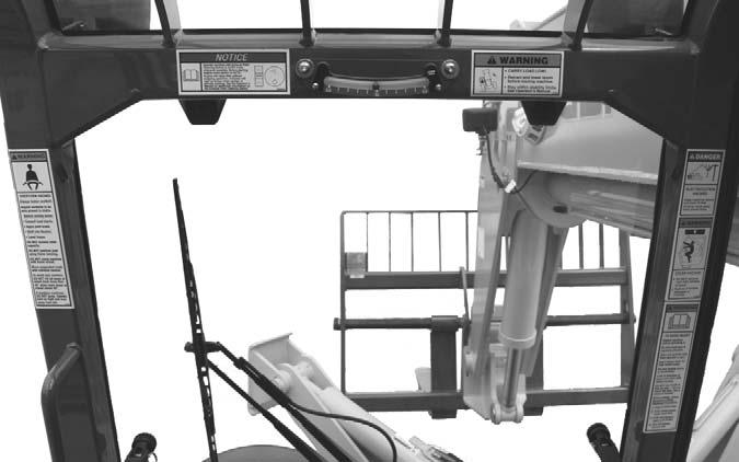
Installing a Personnel Work Platform (PWP)
Warning
The machine must not be used to lift or carry personnel or be fitted with any form of personnel work platform unless fitted with the optional PWP System.
If fitted with the PWP System, the Mandatory Work Platform Safety Rules (p. 14) must be followed at all times while lifting personnel.
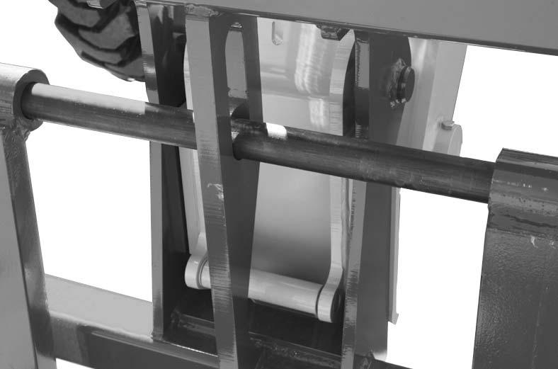
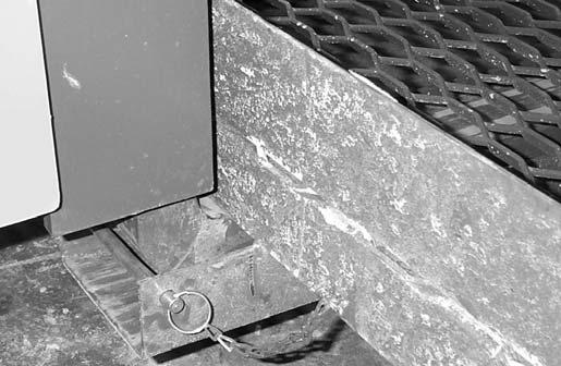
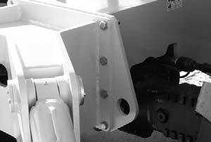
1.Center the forks on the carriage, spaced apart to match the distance required to engage the PWP.
2.After the forks are fully engaged in the PWP, secure the PWP to the forks. This can be accomplished by means of a retaining pin behind the heel of the forks as shown.
Warning
The PWP must meet ANSI/ITSDF B56.6-2005, Section 8.24. (See page 16 in the Safety chapter for PWP design requirements.) If the PWP being used does not offer means to secure the PWP to the forks and to secure the forks from pivoting, as shown in steps 2 and 3, then an alternate method must be used.
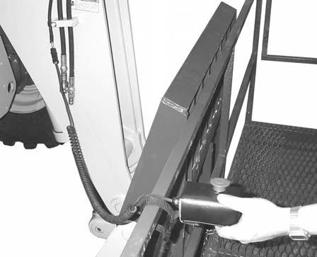
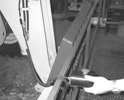
4.On 40’ and 44’ models, connect the coiled wire from the remote shutdown switch to the connector on the end of the boom. Secure the remote shutdown switch to the PWP using the strap attached to the switch, as shown.
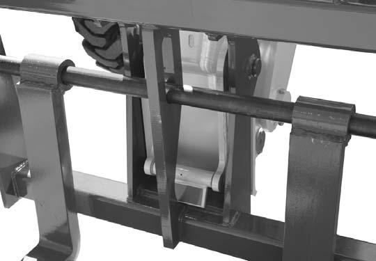
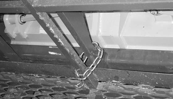
3.Secure the forks from pivoting upward in case the PWP is lowered onto an obstruction. This can be accomplished by using the chain supplied with the PWP, to secure the lower portion of the PWP to the bottom of the carriage, as shown.
Remote Shutdown Switch with Coiled Wire Connector on 40’ and 44’ Models
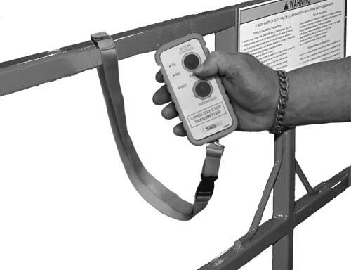
5.On the 55’ model, the remote shutdown switch is wireless-operated. Secure the remote shutdown switch to the PWP using the strap attached to the switch, as shown.
Wireless Remote Shutdown Switch on 55’ Models
6.Secure the lanyard from the body harness to the PWP (or the boom). Each person in the PWP must have a body harness with a lanyard attached to the PWP (or the boom).
Lifting Personnel
The Telescopic Handler is primarily intended for use as a material handler. It should only be used to lift personnel if it is equipped with the (optional) PWP System when there is no other practical option. If this machine is to be used to lift personnel, then use only an approved work platform, lift personnel only with the PWP System activated, and follow the “Mandatory Work Platform Safety Rules” (Safety chapter, p. 15).
If the Telescopic Handler is equipped with a PWP System and is to be used for lifting personnel, the system must be activated, by the “PWP System” mode switch, which is located in the left switch bank. To activate the system, press the top of the PWP rocker switch, apply and hold the service brakes on for three or more seconds. The system is activated when the lamp in the PWP rocker switch is on continuously.
NOTE: If the light is flashing, apply the service brakes until the light stops flashing.
Warning
ALWAYS check the PWP System for proper operation prior to use. (See page 65 for PWP System checking procedure.)
When the PWP System is active: l transmission is de-clutched into Neutral, l parking brake is applied, l rear axle stabilizer cylinder is locked, l frame leveling speed is reduced, l auxiliary hydraulic and carriage tilt and swing functions are disabled, l machine inclination sensor is activated, with the result that the Telescopic Handler must be level laterally (side-to-side) and longitudinally (front-to-back) to the factory pre-set limits before the boom control joystick will function, and l For 40’ and 44’ models, remote shutdown switch is activated, meaning that the switch must be connected and in the “on” position for the boom control joystick to function. Pressing the red button will disengage the boom control joystick, and stop all platform movement. The remote shutdown switch box is supplied with a coiled electrical cable, which must be connected to the outlet on the front of the innermost boom section near the carriage. The switch must be accessible to the platform personnel at all times when the platform is to be moved. l For 55’ model, remote shutdown switch is activated, meaning that the switch must be “on” for the boom control joystick to function. Pressing the red button will disengage the boom control joystick and stop all platform movement. The remote shutdown switch box is a wireless remote control, so there is no direct connection to the Telescopic Handler. The switch must be accessible to the platform personnel at all times when the platform is to be moved.
To de-activate the PWP system, apply the service brakes and press the bottom of the PWP System rocker switch. The system is de-activated when the lamp in the PWP System rocker switch is off.
NOTE: If the lamp in the PWP System rocker switch is flashing, apply the service brakes until the lamp goes off.
Warning
In an emergency, if the platform worker has activated the remote shut-off switch and then is not able to re-activate the switch, such as if the worker fainted, then the Telescopic Handler operator is permitted to turn off the PWP System to regain control of the boom functions, in order to lower the work platform and come to the aid of the worker. But, understand this is only permitted in case of an emergency. Otherwise, the PWP System must be used at all times when there are workers on the platform. This is the only exception!
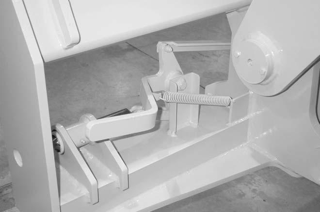
Stabilizer System
This is an additional safety function while elevating loads for placement. At a pre-determined boom angle, the stabilizer cylinder on the rear axle will lock up. When this happens, the parking brake activates and the frame leveling function slows down. Other than moving the boom and slowly leveling the frame, the machine will not be able to move until the boom is lowered below the pre-determined angle.
Warning
The machine becomes less stable as the load is raised higher.
NEVER use frame leveling to position an elevated load. Always lower the load to the ground and reposition the machine.
If a hydraulic boom circuit hose should break with the boom up, shut down the machine. DO NOT attempt to bring down the boom or make repairs. Call your Gehl dealer immediately.
As lift height increases, depth perception decreases. High elevation placement may require a signal person to guide the operator.
DO NOT ram the lift cylinders to the end of the stroke. The resulting jolt could spill the load.
A jib or truss boom should ONLY be used to lift and place loads when the machine is stationary and the frame is level. Transporting suspended loads must ALWAYS be done slowly and cautiously, with the boom and load as low as possible. Use taglines to restrict loads from swinging, to avoid overturn.
Material Handling Bucket Tool Application
IMPORTANT: The 55’ model is not intended for ground or material pile engagement. The bucket should be used for light-duty site cleanup only.
Material Densities
The table on this page lists densities for some common materials that could be carried in a Telescopic Handler bucket tool. The densities listed are average values and intended only as a guide.
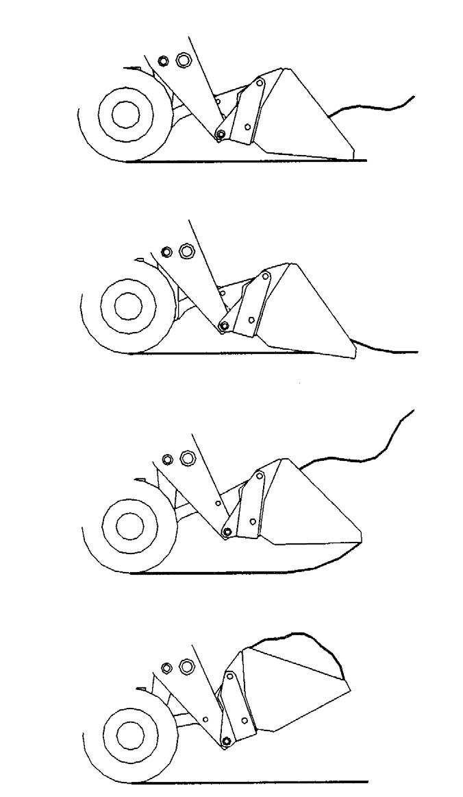
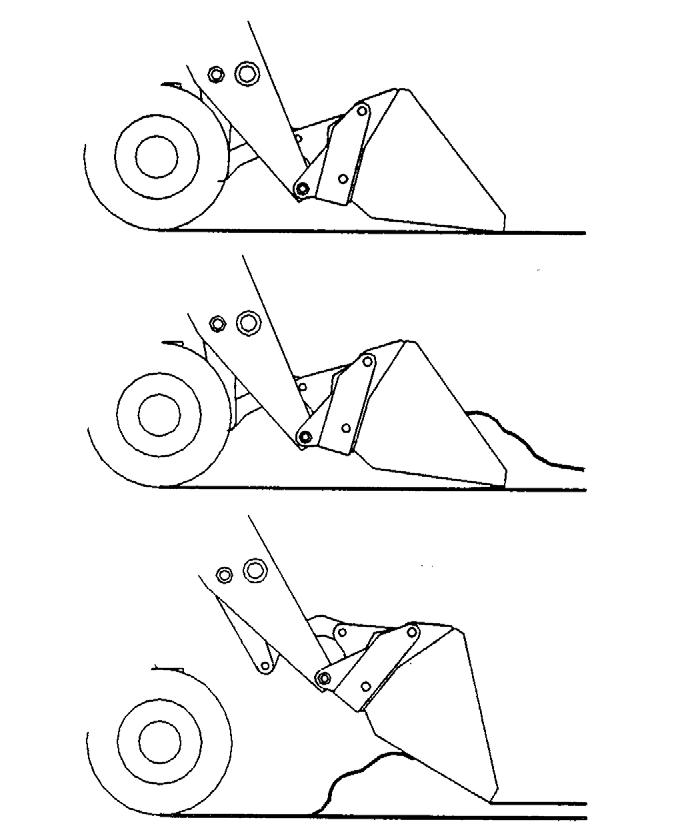
Digging and Loading
Refer to the illustration on th next page. Retract and lower the boom, then tilt the bucket’s cutting edge down into contact with the ground. Drive the bucket into the material. As the engine loads, roll the bucket back slowly and, at the same time, decrease travel speed.
Table of Common Materials & Densities MaterialDensityDensity
Ashes945-1350560-800
Brick-common30241795
Cement29701760
Charcoal621370
Clay2160-27001280-1600
Coal1431-1701850-1010
Concrete31051840
Cinders1350800
Coal-anthracite25381505
Coke810480
Earth-dry loam810480
Earth-wet loam17551040
Granite2511-29971490-1780
Gravel-dry17821060
Gravel-wet24301440
Gypsum-crushed31051840
Iron Ore39152320
Lime1620960
Limestone24301440
Manure-liquid17551040
Manure-solid1215720
Peat-solid1269755
Phosphate-granular24301440
Potash18361090
Quartz-granular29701760
Salt-dry27001600
Salt-Rock-solid36452160
Sand-dry29161730
Sand-wet33752000
Sand-foundry25651520
Shale-crushed24301440
Slag-crushed18901120
Snow405-1350240-800
Sulpha25651520
Taconite28891715
IMPORTANT: ALWAYS fully retract the boom before driving into material.
NOTE: When attempting to fill the bucket while working with most hard-packed materials, it will usually be necessary to raise the boom while rolling back the bucket.
When the bucket is filled, back the machine away from the material and roll back the bucket before proceeding to the dumping area.
Digging Loose Materials
Dumping the Load into a Truck
Digging Hard-Packed Materials Loading Bucket
Carry the loaded bucket low and approach the truck or trailer box, square with the side of the box. Stop as close to the side of the box as possible while still allowing clearance for raising and extending the boom. Raise and extend the boom until the bucket clears the top of the box, and slowly position the bucket over the inside of the box. Then tilt the bucket forward. After the material is dumped, slowly back away from the box, and then retract and lower the boom while rolling back the bucket.
Dumping the Load over an Embankment
Carry the loaded bucket as low as possible while slowly traveling toward the dumping area. Stop the machine at the position where the bucket extends halfway over the edge of the embankment. Then tilt the bucket forward, and raise and extend the boom to dump the material. After the material is dumped, slowly back away from the embankment while retracting and lowering the boom, and then rolling back the bucket.
Carrying Load
Warning
ALWAYS carry a loaded bucket as close to the ground as possible. For additional stability when operating on inclines, ALWAYS travel with bucket end of the machine toward the top of the incline.
Digging, Loading and Carrying Material
Warning
DO NOT drive too close to an excavation or ditch. BE SURE the surrounding ground has adequate strength to support the weight of the machine and load.
Dumping the Load onto a Pile
Carry the loaded bucket as low as possible until reaching the pile. Slowly stop forward motion, then raise and extend the boom high enough so that the bucket clears the top of the pile. Then slowly move the machine ahead to position the bucket, and dump the material on top of the pile. Empty the bucket. Back the machine away while retracting and lowering the boom, and rolling back the bucket.
Scraping with a Bucket
Refer to the illustration. For scraping, the machine should be operated in the forward direction. First, position the boom retracted and down. Next tilt the bucket cutting edge forward at a slight angle. Then travel slowly forward. With the bucket in this position, material can flow over the cutting edge and collect inside the bucket.
Leveling with a Bucket
First, drive the machine to the outer edge of the area to be leveled. Then, with the boom retracted and down, tilt the bucket forward to place the bucket cutting edge at a 30- to 45-degree angle to the surface being leveled. Next, drive the machine rearward while feathering the boom control joystick, dragging the dirt and, at the same time, leveling it.
Road Travel
For short distance highway travel, attach a SlowMoving Vehicle (SMV) emblem (purchased locally) to the back of the Telescopic Handler. Activate the hazard lights on the machine. For highway operation, obtain and install an amber flashing beacon.
NOTE: ALWAYS follow ALL state and local regulations regarding the operation of equipment on or across public highways. Whenever there is an appreciable distance between jobsites, or if driving on public highways is prohibited, transport the machine using a vehicle of appropriate size and capacity.
Transporting Between Jobsites
When transporting the Telescopic Handler, know the overall height to allow for clearance of obstructions. Remove or tape over the Slow-Moving Vehicle (SMV) emblem if it will be visible to traffic.
ALWAYS abide by the following recommended procedures and guidelines when using ramps to load the machine onto (or unload it from) a truck or trailer. Failure to heed can result in damage to equipment and serious personal injury or death!
Tie-down holes are provided for inserting chains through to secure the machine while transporting.

Loading Machine Using Ramps
NOTE: A matched pair of ramps is required.
1.The ramps MUST be of sufficient strength to support the machine. The use of strong steel ramps is recommended, as well as center supporting blocks.
2.The ramps MUST be firmly attached to the truck or trailer bed with NO step between the bed and the ramps.
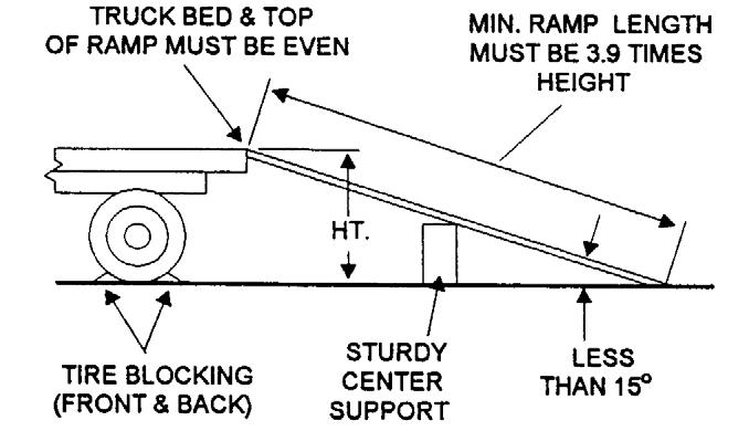
3.The incline of the ramps MUST be less than 15 degrees (ramp length MUST be at least 16 feet (4.9 m) long).
4.Ramp width MUST be at least 1-1/2 times the tire width.
5.Block the front and rear of the tires on the truck or trailer. Engage the parking brake.
6.Position the machine (with the boom facing toward the front of the truck or trailer) so that it is straight in line with the ramps.
7.Slowly (at the lowest engine speed possible) and carefully drive the machine up the ramps.
8.Secure the machine to the bed of the truck or trailer. Tie-down slots are provided on the front and rear sides of the frame structure.
Warning
NEVER adjust travel direction (even slightly) while traveling on the ramps. Instead, back down off the ramps, and then realign the machine with the ramps.
Warning
NEVER transport the machine with the boom raised or extended. BE SURE to secure the machine to the truck or trailer bed using chains and binders or steel cables, to prevent any movement while transporting.
Unloading Machine Using Ramps
NOTE: A matched pair of ramps is required. Repeat steps 1 through 5 and proceed as follows to unload the machine:
6.Remove the tie-down chains/cables.
7.If necessary, adjust the machine so that the wheels are in line and centered with the ramps.
8.Slowly (at the lowest engine speed possible) and carefully drive the machine down the ramps.
Theft Deterrents
Gehl Company has recorded all major component part numbers and serial numbers. Users should take as many of the following actions as possible to discourage theft, to aid in the recovery in the event that the machine is stolen, and to reduce vandalism:
1.Remove keys from unattended machines.
2.Attach, secure, and lock all anti-vandalism and anti-theft devices on the machine.
3.Lock doors of cabs when not in use.
4.Inspect the gates and fences of the vehicle storage yard. If possible, keep machines in well-lighted areas. Ask the local law enforcement agency to make frequent checks around the storage and work sites, especially at night, during weekends, and on holidays.
5.Report any theft to your dealer and insurance company. Provide the model and serial numbers. Request that your dealer forward this information to Gehl Company.