8 minute read
3.8 Duonic


3.8 Duonic
3.8.1 Cautions for vehicles with DUONIC (mechanical automatic transmission)
When removing the DUONIC components and associated parts (piping and wiring included) or performing other works for body mounting, pay particular attention to the following.
Oil cooler piping
• When reinstalling removed oil cooler piping, etc., make sure that the pipe and the DUONIC system components do not contain any foreign matter. The presence of dirt or contamination may cause the system, etc. to malfunction. • After reinstalling, be sure to adjust the automatic transmission fluid level and initialize the DUONIC system.
Clearance
• Make sure that the piping and harnesses maintain at least 25 mm (1 in.) of clear space to other parts.
If this is impractical with parts installed on the same plane, clamp them at proper point(s) to hold them securely.
3.8.2 Automatic transmission fluid level adjustment
After reinstalling removed oil cooler piping, adjust the automatic transmission fluid level as follows.
Automatic transmission fluid level adjustment procedure
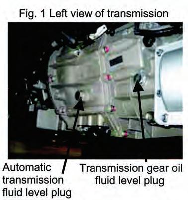
Perform the adjustment in the following sequence. The position of the automatic transmission fluid level plug is the normal fluid level. If the automatic transmission fluid is up to the normal level after the hydraulic circuit is filled up, the adjustment has been properly made.
Automatic transmission fluid level adjustment
Check of automatic transmission fluid level
Automatic transmission fluid is up to level plug. Check of automatic transmission fluid level
Automatic transmission fluid is below level plug.
Supply additional automatic transmission fluid up to level plug.*
Fill automatic transmission fluid in hydraulic circuit as follows:
• Start engine. • While depressing brake pedal, repeat [R] [D] operation of change lever three times. (Hold lever in each range for 3 to 5 seconds.)
Finally, place change lever into [P] position. • Stop engine.
Check of automatic transmission fluid level
Automatic transmission fluid is up to level plug.
End of adjustment Check of automatic transmission fluid level
Automatic transmission fluid is below level plug.
3.8.3 Initialization of DUONIC system
Initializing the DUONIC system stores the GSU (gear shift unit) gear position, road surface grade zero point correction value, clutch fill time learning value and clutch torque learning value in the memory of the TCU. It must be performed after ANY type of transmissionrelated service.
If any abnormality occurs during normal running, it may be cleared by initialization. Some kinds of body equipment work to the vehicle can cause an error in road surface grade recognition. To prevent this, be sure to initialize the DUONIC system under the following conditions after body equipment work.
Conditions for initialization
Check the following before initialization. (a)The engine electronic control unit and DUONIC electronic control unit (TCU) are finished with flashing (programming) and coding (in case of a change in tire size or final ratio). For details, contact a Mitsubishi Fuso service center. (b)To compute the road grade zero point correction value, make sure that the vehicle is in the following state: • Standing still, brake released, on a flat surface such that the vehicle remains stationary without drifting forward or backward • Equipped with specified wheels with the tires filled to correct pressures. • Cab tilt locked (a G sensor is provided in the cab.) (c)For learning the clutch torque, units powered by the engine, such as the following, must be stopped: • Air conditioner • Load for equipment (compressor for refrigerator, etc.) • Exhaust brake
Change lever pattern
Initialization procedure
Operation
• Hold vehicle on flat surface. (3.8.3 (b)) • Turn key ON. • Stop engine. • Switch off air conditioner, equipment load and exhaust brake. (3.8.3 (c)) • Accelerator ON (50% or more) • Foot brake ON • Change lever
D (hold for approx. 1 second) Hold A/M • Parking brake
ON (hold for approx. 1 second) OFF (hold for approx. 1 second) ON (pull a little hard) From initialize mode standby status, • Turn accelerator OFF • Place change lever to [P]. Then, start engine.
Release parking brake or turn key OFF and hold it in that state for 1 second.
Mode is returned to normal.
Resultant status
[Initialize mode standby status] is established and indicator shows [1] blinking.
• With progress of initialization, indicator shows [2-3-4-5-N] blinking in that order. • If initialization goes wrong, [R] is shown blinking. (Status by indication) [2] Detection of GSU gear position in progress [3] Clutch warming up + road grade zero point compensation in progress [4] Clutch fill time learning in progress [5] Clutch torque learning in progress [N] Initialize completed [R] Initialize failed
Remarks
[To clear initialize mode standby status to return to normal mode], release parking brake or turn key OFF and hold it OFF for 1 second.
Even if foot brake is released after engine is started, initialize mode remains, but for safety, foot brake should be kept ON.
(a)In case of failure of initialization • Repeat the initialization procedure from the start. • If initialization still goes wrong, there may be a problem with the hardware. Check the transmission (including gears, clutch, associated parts, valve body and GSU) and their connections. • If the indicator shows from [2] to [R] blinking, move the vehicle once, then perform the initialization procedure. The problem may be resolved.
3.8.4 Resetting of initial DUONIC settings
The DUONIC system has a reset function for restoring the initially set GSU gear position, road grade zero point compensation value, clutch fill time learning value and clutch torque learning value to the preinitialization status. (This is a back-up function used in case any initial settings are found to be abnormal and affect the vehicle operation; it is not normally used.)
Resetting procedure Operation
• Turn key ON. • Stop engine. • Accelerator ON (50% or more) • Foot brake ON • Change lever
D (hold approx. 1 second)
Hold A/M • Parking brake
ON (hold approx. 1 second)
OFF (hold approx. 1 second) ON From initialize mode standby status, place change lever to [–]. Release parking brake, or hold key OFF for 1 second.
Status
[Initialize mode standby status] is established and indicator shows [1] blinking.
With resetting completed, indicator [6] blinks.
Mode returns to normal.
Remarks
[To clear initialize mode standby status to return to normal mode], release parking brake or turn key OFF and hold it OFF for 1 second.
3.8.5 Cautions during body equipment work on DUONIC vehicle
The DUONIC transmission and control system is a computerized and electronically controlled system; mishandling could cause system errors and in the worst case, breakdown of the computer itself. Therefore, body equipment work on the vehicle should be carried out with following the precautions given below.
General handling precautions
• Be sure not to change the tire size, final ratio, and speedometer gear ratio of a DUONIC vehicle. • Be sure not to alter DUONIC-associated devices, sensors, harnesses and connectors in any way. • Before disconnecting DUONIC-associated connectors, set the starter switch of the vehicle to
OFF. Before turning the starter switch ON, reconnect the disconnected connectors.
If DUONIC-associated device connectors are disconnected while power is supplied to the TCU, a warning lamp will light or the system may lose functionality. • Before painting the transmission body, mask electric parts, harnesses, connectors, breathers, oil cooler pipe joints and other parts which should be covered.
Furthermore, mask wrong fluid/oil supply preventive labels (ATF ONLY, GEAR OIL ONLY) attached near to appropriate fluid/oil plugs so that they are not covered with paint. • After completing the body equipment work on the vehicle, make sure that the vehicle runs without any problem.
3.8.6 Power take-off for DUONIC (mechanical automatic transmission)-equipped vehicle
The vehicle cannot be run while the power take-off is in operation.
Vacuum-type power take-off operation procedure
• With the engine running, place the shift lever into the P position (or N position). • Set the power take-off main switch in the cab to
ON. • The indicator lamp lights to indicate that the power take-off is in preparation. • With the indicator lamp on, the power take-off can be used. • To clear this status, set the power take-off main switch in the cab to OFF. The indicator lamp goes off and the indicator lamp goes on. The power take-off is being released.
The indicator lamp goes off to indicate that the power take-off has been released.
Cable type power take-off operation procedure
• With the engine running, place the shift lever to the
P position (or N position). • Set the power take-off main switch in the cab to
ON. • The indicator lamp lights. • Connect the power take-off by means of the power take-off lever or damp lever. • The indicator goes on to indicate that the power take-off is operational. • To release the power take-off, set the power takeoff main switch in the cab to OFF. The indicator lamp goes off and the indicator lamp goes on to indicate that the power take-off is ready to be released.
Release the power take-off by means of the power take-off lever or damp lever. The indicator lamp goes off to indicate that the power take-off has been released.
Cautions
• The indicator lamp may not show, depending on the sequence, operating speed or device response speed, which is not an abnormality. • If the shift lever is in a position other than P or N, the power take-off is not connected even if the power take-off switch is turned ON. In the case where the shift lever is in a position other than P or
N or the power take-off switch is turned to ON during running, the buzzer sounds and the warning indication of appears on the meter. Turning the power take-off switch to OFF restores the state to normal. • If the shift lever is placed into a position other than
P or N or the power take-off switch is turned to ON when the power take-off is working, the buzzer sounds and the warning indication of appears on the meter.