
11 minute read
5.1 Electrical system


5.1 Electrical system
a Risk of fire
Work carried out incorrectly on the electrical system may impair its function. This may lead to the failure of components or parts relevant to safety. All accident prevention regulations must be complied with when working on the vehicle. Comply with all national regulations and laws.
a Risk of fire
Work on live electrical lines carries a risk of short circuit.
Before starting work on the electrical system, disconnect the on-board electrical system from the power source, e.g. battery.

i Observe the notes on operating safety and vehicle safety in Section 1 "Introduction" e page 10 and e page 11.

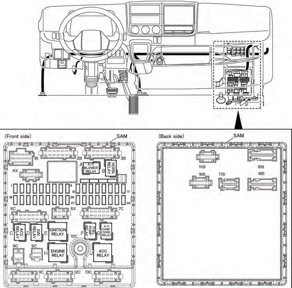
5.1.1 Signal detection and actuation modulerelated parts Cautions on Signal detection and Actuation Module (SAM) (relay and fuse-integrated control unit for body equipment)
The signal detection and actuation module is an integrated unit with the control and power distribution functions for electric parts of the cab and body equipment. (a)Before disconnecting the connected cables of the signal detection and actuation module control unit, set the starter switch of the vehicle to OFF. (b)Before performing welding to the chassis and body, be sure to disconnect the signal detection and actuation module control unit cables and connectors. Use exteme care of spattering (sparks, etc.) thrown on the harnesses during the welding work. Ground the welder near the weld. (c)When cleaning inside the cab, take utmost care not to splash the signal detection and actuation module control unit (including relays, fuses and connectors) with water. (d)When removing the signal detection and actuation module control unit from the vehicle, set the starter switch of the vehicle to OFF, then disconnect the harness from the battery terminals and remove the connectors/nuts in the following order. (To reinstall, reverse the sequence of removal.) • Disconnect the power line (connector No. 9C, nut No. 10C) first. • Disconnect the control unit connectors. • Disconnect the ground line (connector No. 8C) last. • Bracket nuts (back of signal detection and actuation module, M6 x 4)] When installing the signal detection and actuation module control unit to the vehicle, tighten its nuts to the torques specified below.
Nut type Unit: N•m {ft.lbs, kgf•m}
Torque Use
M6 4 to 6 {3 to 4.4, 0.4 to 0.6} nominal value: 5.4 {4, 0.55} To mount the control unit to the bracket
M8 10 to 15 {7.2 to 11.0, 1 to 1.5} nominal value: 12.7 {9.3, 1.3} To mount the power line 10C
5.1 Electrical system
(e)Relays and fuses should be carefully installed or removed in/from the signal detection and actuation module control unit one by one.
Cautions to be taken when handling signal detection and actuation module related parts
To protect the functions of the SAM, be sure NOT to: (a)Alter electrical routing by extending or cutting a power cable or connector to/from other parts than the connector used for body equipment or other similar methods. (b)Alter the SAM control unit in any way. (c)Remove or paint the cover of the SAM control unit.
Output terminals for additional wiring
The SAM control unit has circuit output terminals for additional wiring as listed below. Connect power or signal cables to the connectors used for body equipment to add the wiring as required.
(a)Cautions when using output terminals for additional wiring • Allowable current values are specified for the output terminals. Make sure that the rated current for any additional electric part to be used is lower than the specified allowable current. • When any diagnostic function of the output terminals marked * is used, it is necessary to change data for the SAM. For details, ask the contact person. • When a signal output terminal is used to operate any body equipment-side apparatus, use it as the activating side for operation relay. The relay used must be a noise-absorbing element-incorporated type. • For necessary output lead-out connectors, see "Mounting Location of Optional Terminal Inside Cab" e page 103.
Other precautions
When the following parts are mounted, it is necessary to change data for the SAM. For details, ask the contact person e page 15. • Switch for mirror with heater: Momentary type (MK645411 or equivalent) • Heated mirror: Operation current: 6 A (Type: 12 V) • Designated LED rear lamp
Circuit name Allowable current
Power supply (Batt) 7 A Power supply (ACC) 7 A Power supply (key-on) 7 A ILL power supply* 2.5 A (chassis harness side) 2.5 A (body harness side) Neutral signal* 0.2 A Power take-off signal* 0.2 A Parking brake signal* 0.2 A Back alarm signal* 0.2 A
5.1 Electrical system
5.1.2 Starter switch
• The starter switch uses precision current contacts.
Do not add any wiring to the line connected to the starter switch. • Regarding the output terminals for additional wiring provided on the SAM control unit, see "5.1.1
Signal detection and actuation module-related parts" (e page 53).
5.1.3 Fuse
(a)Do not route power wiring from any fuse for unintended use. The existing fuse on the chassis side is of the optimum capacity for the service load, frequency of use, etc. When installing an additional electrical device associated with body equipment, do not connect parts or harnesses which may provide an error signal to the chassis power line or ground line.
Be sure to lead out power for body equipmentrelated apparatus and lamps via designated appropriate connectors. For further details, see "Mounting Location of Optional Terminal Inside
Cab" (e page 103).
Fuses in the cab are provided on the signal detection and actuation module control SAM unit. When removing and reinstalling them, do
so securely one by one. For other precautions on the SAM, see "5.1.1 Signal detection and actuation module-related parts" (e page 53). (b)Mid-point extension of existing wiring or the use of a larger capacity fuse could cause an excessive current to flow in the power fuse box, resulting in a fire. (c)Arrangement of power fuses, relay in the instrument panel, sensors and ECU • Fuse layout drawing
5.1 Electrical system
5.1 Electrical system
Fuse No. Major load Capacity
F01 F02 F03 F04 F05 F06 F07 F08 F09 F10 F11 F12 F13 F14 F15 F16 F17 F18 Starter -
Optional power (IGN) Power window (driver’s seat side)
Power window (passenger side) ID lanp Meter, diaphragm tachometer, diagnosis connecter Blower fan Audio, interior lamp Starter switch, ISS ECU Horn Audio Power mirror, power socket (cigarette lighter) Fuel heater ABS ECU
F19 F20 F21 Engine ECU 4WD M/V -
F22
Meters, A/C control - F23 F24 F25 F26 F27 F28 F29 F30 F31 F32 F33 F34 DUONIC ECU Optional power supply (ACC) Optional power supply (B+) Van body dome lamp Engine ECU BlueTec system R BlueTec systemR Engine ECU Air conditioner Fuel pump 10A -
10A 30A
30A 20A 10A 30A 15A 10A 10A 10A 20A 20A 10A 15A 10A 10A 15A 10A 10A 10A 10A 20A 15A 20A 20A 20A 10A 15A
• Removal of spare fuse
To remove the spare fuse, insert a fuse puller from outside the wall holding the spare fuse. Do not insert the puller from inside the wall, as doing so could damage the fuse holder and cause electrical failure or fire.
• Arrangement of relay in the instrument panel, sensors and ECU
5.1 Electrical system
5.1.4 Connecting additional power wiring
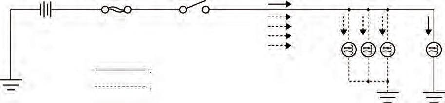
• Taking power from the existing wiring (a)Source the power for the lamps and devices of the built body from the specified connector. If an electrical device related to the built body is to be added, do not install a part or route a harness that can give a false signal to the power line and ground line of the electrical devices on the vehicle side. Adding a wire to a midway point of the existing wire or increasing capacity by changing the fuse causes an excessive current to flow through the power supply and fuse box, leading to a fire. NEVER change or add electrical wires except for those contained in this manual. Increase the number of lamps according to the table given below (load, power source, etc.). (b)Typical faulty wiring
• Taking power via the onboard battery terminal
Take power by way of the onboard battery terminal only when doing that is absolutely necessary to achieve body building. If it is done unavoidably, observe the following precautions. (a)Add a fuse of a correct type to any additional wire to thereby protect the circuit. (b)Use a wire of 5.0 mm2 (0.2 in.2) or more for the additional wire ("between battery terminal and fuse" of the next figure (e page 60). Set the wire as short as possible and make sure that its jacket is not damaged to result in a short. (c)For the combination of the capacity of the additional fuse and the wire size between the fuse and the additional load, study those marked with v in "List of recommended combinations of fuse capacity and wire size" (e page 60). (d)Install the additional fuse in a waterproof cover (e.g. electric cover) or take an equivalent waterproofing measure for the additional fuse.
Do not add wires or fuses to the existing highcurrent fuse box. (e)Use of a directly connected power supply causes the onboard battery to tend to run down quickly. Make sure that the customer understands and observes the following handling precautions: • It is prohibited to use the onboard battery for a long time with the engine stationary. Do not use the onboard battery as a service power supply (for the clock, memory, etc.).
Battery High-current fuse Switch
Existing wire Additional wires
5.1 Electrical system
The amount of current is increased by the additional lamps, which applies load on the switch, fuse, and wires, resulting in a fire.
Additional lamps Existing lamp
Between battery terminal and fuse
Addition on the built body Additional fuse, etc.
5.1 Electrical system
Ground point
Battery cable (-)
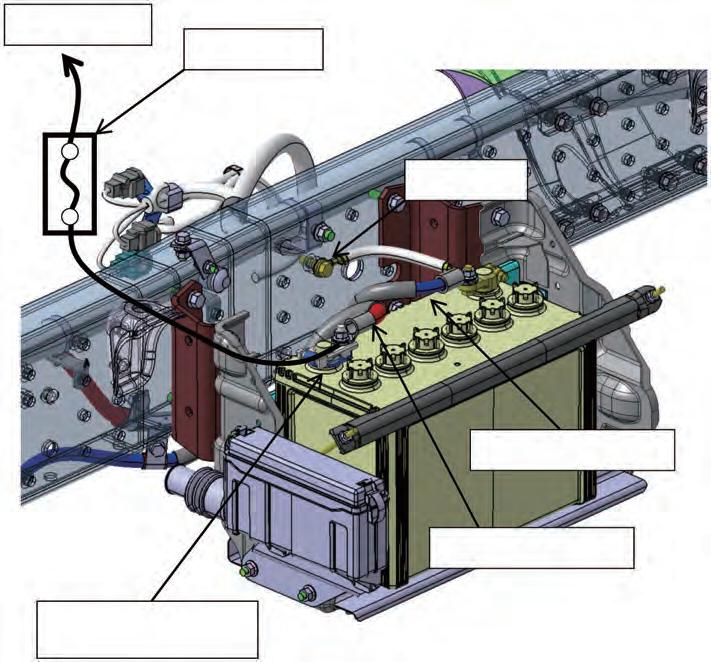
Battery cable (+)
Terminal for taking power on built body side, M8 screw
(f)Use a round flat terminal for the power supply terminal and jointly fasten it by using the fixing nut for attaching the battery cable terminal.
Only one power supply terminal may be used.
Two or more additional terminals can be loosened, resulting in heat being generated or a short.
List of recommended combinations of fuse capacity and wire size
v : Usable u : Not usable
Fuse Wire size [upper] and wire permissible current [lower]
Type Specifications
0.3 0.012
0.5 0.020 0.85 0.033 1.25 0.049
2.0 0.079
3.0 0.120
5.0 0.200
(mm2) (in.2) 11 14 18 23 31 42 57 (A)
Blade and glass tube
5 A v v v v v v v 7.5 A v v v v v v v 10 A u v v v v v v 15 A u u v v v v v Note: Keep the continuous permissible current within 70 % of the fuse specifications value. (E.g.) If the fuse used is 10 A: 10 0.7 = 7 (A) R A load of up to 7 A can be used.
Notes: 1. u: Not usable; — : 50 m (165 ft) max 2. AV/AVS wires: general wires; AVX wires: heat-resistant wires
5.1.5 Batteries
• Never place any metal objects or tools on the batteries. • There is a risk of short circuit if the positive terminal clamp on the connected battery comes into contact with vehicle parts. This could cause the highly explosive gas mixture to ignite. You and others could be seriously injured as a result. • When disconnecting the batteries, always disconnect the negative terminal clamp first and then the positive terminal. • When connecting the batteries, always connect the positive terminal clamp first and then the negative terminal. • Incorrect polarity of the supply voltage can cause irreparable damage to the control units. • Never start the engine without a connected battery (battery terminals tightened). • Do not disconnect or remove the battery terminals while the engine is running. • If the batteries are flat, the engine can be jumpstarted using jump leads connected to the batteries of another vehicle. Observe the Instruction Manual.
Do not use a quick charger for jump-starting. • Only tow-start the vehicle with the batteries connected. • Quick-charge the batteries only after disconnecting them from the vehicle's electrical system. Both the positive and negative terminals must be disconnected.
5.1.6 Lines, plug connections and control units
• A plug connection must not be unplugged from or plugged into the control unit(s) while the ignition is on. • Lines must be protected from heat by means of insulation. • Route cables in such a way that chafing cannot occur, particularly at crossover points and sharp edges. If necessary, use cable ducts, insulating loom, or guide pipes. • Do not carry out tests at connector terminals using unsuitable tools (test probes, wire ends, etc.). This may lead to contact damage and subsequent problems. Use suitable test leads. • The contact persons must be consulted if a battery isolating switch is to be retrofitted e page 15.
5.1 Electrical system
i Installing additional electrical consumers e page 100.