6 minute read
7.5 Fuel tank


7.5 Fuel tank
7.5.1 Cautions relating to fuel tank
Be cautious while installing the rear fuel tank piping. Do not let it interfere with the body. Do not allow foreign materials to enter the fuel tank and related parts. Install all fuel hoses so that there is no slack, or broken parts and make sure that the hose is free to accept fuel. If a hose is too long, shortening may be required. The temporary rubber cap on the fuel tank filler frame pass through must be removed. Clip part number MH021308 must be reused.
When inserting fuel filler hose MK517156, make sure that the hose is completely against the seat (spool) of the filler pipe. Install in accordance with the illustration printed below. Make sure there is no interference with the breather hose.
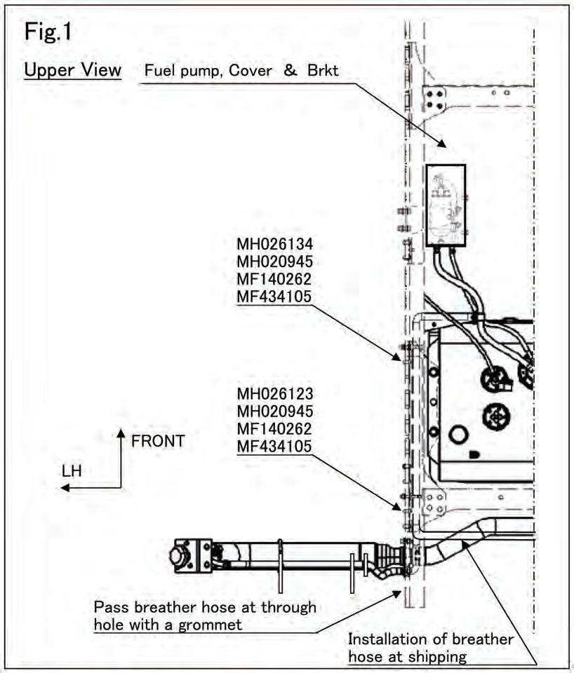
Remove the two tie wraps that temporarily hold the breather hose in the shipping position. Insert more than 20 mm {0.79 in.} of the breather hose MK456266 to the filler end pipe and retain it using clamp MH021302. Position the breather hose using clamps MH020945 to points indicated in the illustration below. Secure breather hose to the filler pipe using tie wraps ME292602 in two places. Refer to Fig. 1, Fig. 2 and indicated in Section 9.13 Fuel tank mounting layout. The fuel filler end must be attached to the rear body structure. The rear body structure must be strong enough to support the weight of all components. The filler pipe must not be allowed to project beyond the side of the body. The fuel filler pipe MUST be located at least 171.5 mm {6.75 in.} above the height of the upper truck frame flange. This will allow satisfactory fill speed. Attach the fuel cap tether. See Section 9.13 Fuel tank mounting layout. The air vent valve inclination must be approximately 25 degrees to vertical. Attach caution label MK587871 where it will be readily seen. Inspect the system and ensure that all attaching hardware is secure. Make sure there are no leaks or restrictions.
Unit: mm (in.)
Unit: N·m {ft.lbs, kgf·m} Part Tightening torque Remarks Screw of Clamp 3.9 ± 1.0 {2.9 ± 0.7, 0.4 ± 0.1} Filler end 8 to 12 {5.9 to 8.8, 0.8 to 1.2} With tether of filler cap
7.5.2 Instructions for relocating the tank
• Avoid unnecessary moving of the fuel tank. If it is necessary to do so, follow the cautions listed below and obtain the advice from NAFTA. • Use Mitsubishi Fuso authorized fuel hose when replacing. • Keep the distance from the filler end and the end of air vent hose to; • Over 300 mm {11.8 in.} to exhaust exit • Over 200 mm {7.87 in.} to exposed electric terminal • Don't connect the fuel piping over the exhaust pipes. Set the connection point where the fuel will not splash on the exhaust system even if it will leak. • Install the tank securely to be free from loosening or other defect with consideration of the effect of vibration, layout, and other factors. Any custom mounting brackets must be designed for sufficient strength. • Don't modify the Mitsubishi Fuso genuine tank. • Use following flange bolt and nut for mounting the tank, and tighten them with following torque.
Some of the bolts that fix the tank on the frame are tightened with frame component such as C/MBR.
These bolts and nuts must be tightened securely again with new parts if you remove them through the relocating process. • Prevent direct contact of any metal parts (as clamp to fix the fuel pump to brkt) to the fuel pump housing to avoid electro chemical corrosion: use plastic or rubber isolation between the fuel pump and brkt. • Attach a cover to the fuel pump, and the fuel pump must be installed in the position that does not catch mud and spray.
A
Unit: N·m {ft.lbs, kgf·m} Model Name Size Strength Grade Tightening torque
FE BOLT, FLANGE M10 8T or more NUT, FLANGE M10 6T
BOLT
M14 8.8 or more NUT, FLANGE M14 6T 50 to 65 {37 to 48, 5.1 to 6.6}
130 to 170 {95 to 125, 13.3 to 17.3}
FG BOLT, FLANGE M10 NUT, FLANGE M10 10T 6T 90 to 110 {66 to 81, 9.2 to 11.2}
7.5.3 Moving the fuel tank
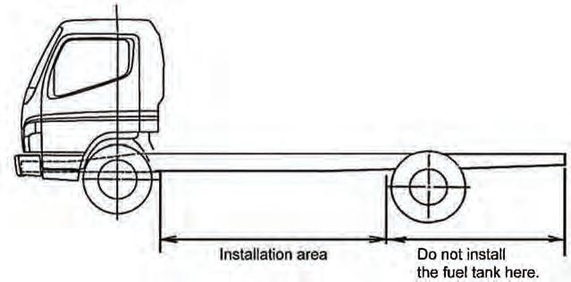
Install a FHWA-approved fuel tank within the wheelbase. Consult NAFTA before installing it in other locations.
7.5.4 Fuel tubes
• Use rubber or metal tubes specified below when changing the fuel lines. (a)Fuel hose Fuel hoses of poor quality may cause a fire. Always use the standard MFTBC products described below.
Supply tube
Return tube Inside dia. mm {in.} MFTBC Part No. Length mm {in.}
11.5 {0.45} MH030*** 120 to 20000 (4.72 to 787.4)
9.5 {0.37} MH030***
6.2 {0.24} MS602***
80 to 6500 (3.15 to 225.9) 40 to 10000 (1.57 to 393.7)
Note: Check with NAFTA for corresponding details regarding the part numbers and length. (b)Metal tube
Outside dia. mm {in.} Thickness mm {in.} Material
Supply tube 8 {0.31} 0.7 {0.028} SPCC (JIS) (ASTM A109 or A366) Return tube 10 {0.39} 0.7 {0.028} Single rolled steel pipe
7.6 BlueTec® system
(c)Fuel Nylon tube
• Never extend the fuel lines. • Use metal tubing for the fuel line inside the engine compartment. • Never modify the clips or move the location of clamps for components in the engine compartment which can be moved. • Never install tubes together with electrical wires. • Follow the procedures described in Section 9 "EXHAUST SYSTEM" when modifying exhaust system components. Install a Heat insulation panel if the specified clearances cannot be maintained. • Be sure to position the fuel lines so that if a fuel leak should somehow occur, the fuel will not drip onto the muffler or exhaust pipe. Never connect the fuel lines above the exhaust system. • Use the nylon hose and the metal tube for connection with the fuel tank of the supply piping and the return piping.
The end shape of the metal tube must be conformed by SAE J2044 standard.
Otherwise it may cause fuel leakage.
Please be sure to use the specified nylon hose and metal tube. • Never use the rubber hose to the supply line (From the fuel pump to the engine)
Outside dia. mm {in.} MFTBC Part No. Length mm {in.} Application Part
8 {0.31} MK629953 1,000 {39.4} Fuel Tank - Fuel Filter 8 {0.31} MK629955 1,500 {59.1} Fuel Tank - Fuel Filter 8 {0.31} MK629957 2,000 {78.7} Fuel Tank - Fuel Filter 8 {0.31} MK629959 3,000 {118.1} Fuel Tank - Fuel Filter 8 {0.31} MK629961 1,000 {39.4} Fuel Filter - Supply Pipe 8 {0.31} MK629963 1,500 {59.1} Fuel Filter - Supply Pipe 8 {0.31} MK629965 2,000 {78.7} Fuel Filter - Supply Pipe 8 {0.31} MK629967 3,000 {118.1} Fuel Filter - Supply Pipe 10 {0.39} MK629969 1,000 {39.4} Return Pipe - Fuel Tank 10 {0.39} MK629971 1,500 {59.1} Return Pipe - Fuel Tank 10 {0.39} MK629973 2,000 {78.7} Return Pipe - Fuel Tank 10 {0.39} MK629975 3,000 {118.1} Return Pipe - Fuel Tank
7.5.5 Others
• Observe the procedures described in Section 6 "ELECTRICAL WIRING" when modifying the wires connected with the fuel tank. • Place the filler port of the fuel tank to allow easy fueling. e page 122.