MAINTENANCE Impeller Removing and Reinstallation (figures 13a-13b) TO REMOVE THE IMPELLER:
TO REINSTALL THE IMPELLER:
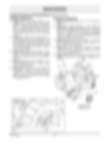
1. Figure 13a: If the debris blower is in storage, remove the round wire lockpin (item 1). Then remove the 1/4" cotter pin (item 2), the flat washer (item 3) and the wheel assembly (item 4). Place the arm on a small wood block as a temporary support. 2. Figure 13a: Attach the housing (item 7) to a hoist with the hook provided on the housing (item 5). Remove the twelve 3/8" NC serrated flange nuts (item 6) and move the housing to the front to take it out from the impeller. 3. Figure 13b: Remove the 1/2"NC x 1" hex bolt, the lockwasher and the flat washer (items 2, 3 and 4) in front of the impeller (item 1). 4. Figure 13b: Remove the 1/2"NC x 3 1/2" hex bolt (item 5) and the 1/2"NC nylon insert locknut (item 6). 5. Figure 13b: The impeller is provided with an ejection device, so just screw a 3/4"NC x +/- 2 1/2" hex bolt (item 7) that pushes against the shaft end and ejects the impeller (item 1).
1. Figure 13b: Remove the 3/4" x +/- 2 1/2" hex bolt (item7). 2. Figure 13b: Apply grease on the shaft to facilitate the reinstallation. Make sure to align the hole in the impeller with the hole on the shaft, where the 1/2"NC x 3 1/2" hex bolt was installed (item 5). A light punch on the impeller should be enough to insert it on the shaft. 3. Figure 13b: Attach with the 1/2"NC x 1" hex bolt, the lockwasher and the flat washer (items 2, 3 and 4) in front of the impeller. 4. Figure 13b: Then attach the impeller with the 1/2"NC x 3 1/2" hex bolt (item 5) and the 1/2"NC nylon insert locknut (item 6). 5. Figure 13a: Reinstall the front housing and the wheels (follow the preceding procedure in reverse).
Figure 13b Figure 13a
OM 0401-A
25

