10 minute read
DECALS

from Frontier Root Grapple Loader Attachments AV20 Owner’s Operator's Manual(5WS105006) - PDF DOWNLOAD

Tractor Preparation
See Dealer for Tractor Preparation information.
Debris Blower Assembly
Use the present manual and lay out all parts for assembly. Separate bolts and nuts into various sizes. After assembly, torque all the bolts according to the Torque Specification Table at the end of the manual.
Debris Blower removing front wooden crate (Fig. 1)
1. Remove the six 3/8"NC x 3/4" carriage bolt and six 3/8"NC serrated flange nut to remove the belt protector (item 1).
2. Keep the hardware for further use. Remove the four screws (item 4) and 1/4" flat washers (item 5) that maintain the Debris Blower to the crate.
3. Reinstall the belt protector (item 1) with the six 3/8"NC x 3/4" carriage bolt and six 3/8"NC serrated flange nut removed previously.
4. Remove the three round wire lock pins (item 6) from the wheel support pins and attach them in the holes provided on the side of the Debris Blower (item A).
5. You may use the two lifting holes (item 7) to move the Debris Blower more easily.
Debris Blower Installation (Figures 2-3)
1. For installation on a Tractor equipped with a HP2134-HP2120 Hydraulic Unit: Keep the ø3/4"NPT quick couplers already installed on hoses.
2. For installation on a Tractor equipped with a HP2025 Hydraulic Unit:
Figure 2: Install the ø1/2"NPT quick couplers attached to the hoses with a plastic film.
A- Remove the ø3/4" NPT female quick coupler (item 3). With thread sealant, install the ø1/2" NPT female quick coupler (item 1).
B- Remove the ø3/4" NPT male quick coupler (item 4). With thread sealant, install the ø1/2" NPT male quick coupler (item 2).
C- The ø3/4"NPT male and female quick couplers won't be needed any further.
3. Figure 3: Install the two universal hitch hooks (item 1) to the two front load brackets (item 2). Insert the two universal hitch pins (item 3) in the front load bracket holes (item 4) and secure with two linchpins provided with the front load brackets (item 5).
Installation of the Hydraulic Hoses (Figures 4-5)
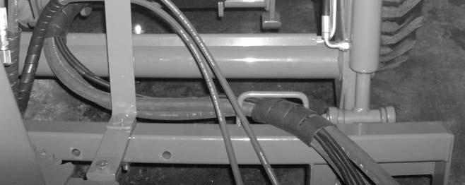
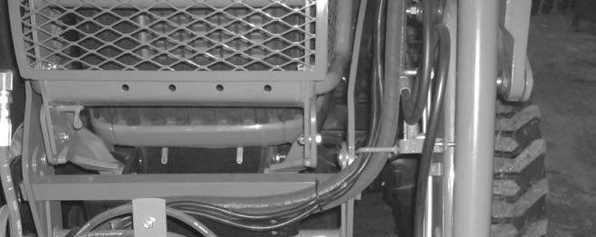
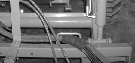
1. Figure 4: Insert the hydraulic hoses (items 12) through the hose support of the universal hitch (item 3) then through the front support of the loader (item 4). Make sure the hose protector (item 5) is under the bar of the universal hitch hose support (item 3). Place the other hose protector (item 7) above the front loader tube (item 6).
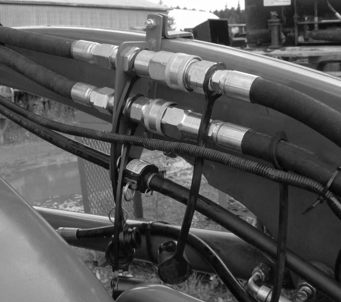
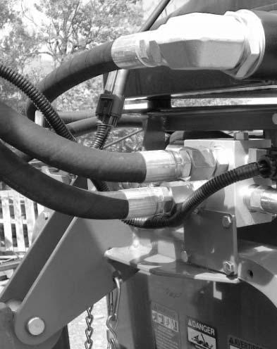
2. Figure 5: Connect the male coupler of the debris blower hose (item 1) to female coupler of the hydraulic pump hose (item 2). Connect the female coupler of the debris blower hose (item 3) to male coupler of the hydraulic pump hose (item 4).
Installation of the Cooling Unit 5RDF0036 (Figures 6a to 6g)
For Debris blower working in warm region, use the 5RDF0036 oil cooler. If you own a HP2120 power unit, use the 5RDF0037 cooling unit upgrade.
IMPORTANT: To not damage the oil cooler, it is essential to disconnect the fan of the oil cooler when the temperature is under 0°C.
NOTE: The new HP2025 and HP2134 pumps are equipped with a safety system to prevent the hydraulic oil from overheating. When the hydraulic block is not power supplied, the oil is in recirculation mode meaning that the equipment will not function. To power the block, refer to the Hydraulic Pump Manual.
1. Figure 6a: Unscrew the 1 1/16" JIC elbow (item 1) from the in-tank filter. Remove the 3/4"NC x 2" lg bolt (item 2) and the stover nut (item 3). Remove the stover nut (item 4) from the 3/4"NC x 4 1/2" lg bolt but do not remove the bolt.
2. Figure 6b: Unscrew the straight 1-1/16"JIC adapter (item 1) and rotate the hose of 90 ° up to bring up the 90° 1-1/16"JIC elbow adapter (item 2). Tighten the straight 1-1/16"JIC adapter, to rotate the hose, at 65-75 ft-lb (93-101 N-M).
3. Figure 6c: Install the oil cooler support (item 1) with a 3/4" NC x 2" lg bolt (item 2) and the 3/4" stover nut (item 3) removed previously. Reinstall the 3/4" NC stover nut (item 4) previously removed on the 3/4" NC x 4 1/2" bolt.
4. Figure 6d: Install the support plates (item 1) with six 5/16" NC x 1" bolts (item 2), eight 5/16" flat washers (item 3) and six 5/16" NC nylon insert nuts (item 4) making sure to place a flat washer between the support plates and the "U" section of the frame.
5. Figure 6e: Install the rubber bushings (items 12) on the support then attach the oil cooler (item 3) with four 5/16" NC x 2 1/4" bolts (item 4), 5/16" flat washers (item 5), the flat washers supplied with the rubber bushings (item 6) and 5/16" NC nylon insert nuts (item 7).
IMPORTANT: Position the oil cooler so the bypass valve (item 8) faces the rear as illustrated.
6. Figure 6f: Install the 1 5/8" ORB – 1 1/16" JIC elbows (item 1) on the oil cooler's inlet and outlet in the positions illustrated. Connect the straight end of the outlet hose (item 2) to the oil cooler elbow and the bent end to the filter. Connect the inlet hose (item 3) previously disconnected from the filter to the other elbow making sure it passes outside the support plate (item 4).
7. Figure 6g: Connect the oil cooler fan harness (item 1) to the available connector on the hydraulic pump's wiring harness (item 2).
Removing Debris Blower from Tractor (Figures 7 to 10)
1. Set parking brake and turn engine off.
2. Figure 7: Direct the wheel supports (item 2) along the housing support tube (as illustrated) and lock in position with three round wire lock pins (item 1), that are attached to the debris blower housing (item A).
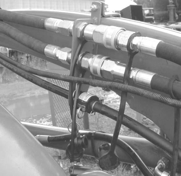
3. Figure 8: Disconnect the male coupler (item 1) of the debris blower hose from the female coupler (item 2) of the hydraulic pump hose. Disconnect the female coupler (item 3) of the debris blower hose from the male coupler (item 4) of the hydraulic pump hose. Install the dust caps (item 5) on each coupler (items 1-2-3-4).
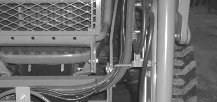
4. Figure 9: Remove the hydraulic hoses (items 1-2) from the front support of the loader (item 3). Roll up the hoses around the universal hitch so they don't drag on the ground.
5. Figure 10: Remove the two linchpins (item 5). Disengage the two universal hitch pins (item 3) from the holes of the front loader (item 4).
6. Figure 10: Disengage the two universal hitch hooks (item 1) from the loader brackets (item 2). Back away slowly.
IMPORTANT: To avoid damages to the debris blower, retorque all bolts after the first 10 hours of operation.
Optimum Performances
IMPORTANT: The hydraulic motors of the rotary broom must have a breaking in period. If it is not respected, the warranty could be voided. The breaking in period must follow these steps:
1- 15-30 minutes of operation at half engine speed (tractor RPM around 1250).
2- Check for unusual noises coming from the motors. If everything sounds normal, the load and engine speed can be increased.
The new HP2025 and HP2134 pumps are equipped with a safety system to prevent the hydraulic oil from overheating. When the hydraulic block is not power supplied, the oil is in recirculation mode meaning that the equipment will not function. To power the block, the ignition key must be in the "ON" or "START" position. If the system remains in the recirculation mode, refer to the "Troubleshooting" section at page 26.
General Preparation
1. Read the operator’s manual carefully before using the tractor and debris blower. Be thoroughly familiar with the controls and proper use of the equipment. Know how to stop the unit and disengage the controls quickly.
2. Make sure the impeller operates freely.
3. Check the shear bolt on the PTO, for proper tightness.
4. Wear adequate winter outer garments while operating equipment.
WARNING: To avoid serious injuries or death:
• Do not allow bystanders near working area.
• Do not allow anyone to ride on debris blower.
• Before cleaning, adjusting or repairing the debris blower: bring the tractor to a complete stop, wait for all movement to stop, apply parking brake, lower the implement to the ground, shut off the engine and remove the ignition key.
• Never put any part of your body under the debris blower while making adjustments.
WARNING: To avoid serious injuries:
• Always operate the debris blower from the operator's seat only. Never allow anyone to ride on the machine.
• Operate the debris blower at a speed that matches the working conditions. Be extremely careful when working on banks or uneven terrain.
• Always wear protective eyewear when operating the debris blower.
Operating Controls
Debris Blower Commands
1. Use the PTO button to start and stop the impeller. Start the engine and put the throttle lever at low engine speed. Engage the PTO lever and maintain engaged. Make sure the debris blower is turning in the right direction. If not, switch the quick couplers. To stop the rotation, disengage the PTO button.
2. Never engage or disengage the debris blower at high engine speed or the hydraulic motor(s) could get damaged.
3. Raise and lower the debris blower using the hydraulic lift lever located on the tractor. Pulling the lever backward raises the debris blower, pushing the lever forward lowers the debris blower.
4. Control impeller speed with the RPM that controls the debris ejection power.
Debris Blower Utilization
1. A debris blower purpose to displace rather light debris to a variable distance according to the impeller speed. For heavy debris, it is recommended using some other equipment type such as a rotary broom. For an optimum performance, lower the debris blower as the 3 wheels touch the ground. Make sure the loader control lever is in floating position to allow the equipment to follow the ground variation and so more debris to be blown.
WARNING: To avoid equipment damage : never raise the tractor front with the debris blower.
2. For light debris, use a higher vehicle ground speed. For heavier debris, use a reduced vehicle ground speed. For small area, lower the tractor motor speed to eject debris on a short distance. For wider area, use higher speed.
Nozzle air ejection Orientation
Equipment air ejection can be done to the right or the left. To change direction, move the orientation arms on the debris blower. See decal on equipment to check arm positions for right orientation.
WARNING: To avoid serious injuries: never move the orientation arm when the debris blower is running.
Adjustments
Belt Tension Adjustment (Figure 11)
1. Remove the belt protector (item 5) by removing the six 3/8"NC x 3/4" carriage bolts and six serrated flange nuts (items 6-7).
2. Loosen the eight 1/2"NC nylon insert locknut (item 1).
3. Tighten eyebolt nuts (item 2). With a belt tension gauge check for a 35lbs tension and a 3/16" displacement in the center in all belt axis (item 3).
4. Realign the driving pulley assembly (item 4) by pressing the support against the bolted guides. Tighten loosely the eight 1/2"NC nylon insert locknuts (item 2) loosen previously. With a long ruler that may cover the distance between pulleys, check the pulleys alignment, If alignment is good, tighten the eight 1/2"NC nylon insert locknuts (item 2). If not, follow next step.
5. If the belts are not well aligned, loosen the guide nuts and the eyebolt nuts. Align the two pulleys, slightly tighten the eight 1/2"NC nylon insert locknuts (item 2). Press the guides against the driving pulley assembly (item 4) and tighten guide nuts. Redo step 2. Check the pulleys alignment and if the driving pulley assembly is well pressed on guides. If so, tighten firmly the eight 1/2"NC nylon insert locknuts. If not, repeat procedure.
6. Reinstall the belt protector (item 5) with the six 3/8"NC x 3/4" carriage bolts and six serrated flange nuts (items 6-7).
Figure 11
Maintenance
ALWAYS USE GENUINE PARTS WHEN REPLACEMENT PARTS ARE REQUIRED
Storage
1. Check hardware at regular intervals to ensure it is always tightened properly.
2. Never park the tractor inside a building where an open flame or sparks are present. Allow the engine to cool down before storing in any enclosure.
WARNING: Provide adequate blocking before working under the debris blower when in raised position.
Hydraulic Oil
Check oil level before each use. Refer to the operation's manual of the HP2120, HP2025 and HP2134 hydraulic pumps.
IMPORTANT: If you own a HP2120 hydraulic pump, it is recommended to use the 5RDF0037 update kit.
ATTENTION: Escaping hydraulic/diesel fluid under pressure can penetrate the skin causing severe injuries.
• Do not use your hands to check for leaks. Use a piece of cardboard or paper to search for leaks.
1. Hydraulic line
2. Cardboard
3. Magnifying glass
• Shut engine off and relieve pressure before connecting or disconnecting lines.
• Tighten all connections before starting engine or pressurizing lines.
• If any fluid is injected into the skin, obtain medical attention immediately or gangrene may result.
Lubrication
Use oil or a grease gun and lubricate as follows:
Bearing And Wheels
Periodic Checks
Hoses
Hydraulic motor
Housing, hitches, impeller wheel supports
Hardware
Grease each bearing of the impeller shaft, the wheel support pins and the wheels.
Belt Replacement (figures 12a-12b)
1. Figure 12a: Remove the belt guard (item 1) and the six 3/8"NC x 3/4" carriage bolts (item 2) and six 3/8"NC serrated flange nuts (item 3).
2. Figure 12a: Remove the 1/2"NC x 2 1/2" bolt hex (item 4) and the 1/2" lockwasher (item 5), the 1/2" flat washer (item 6), the spacer (item 7) and the 1/2" nylon insert locknut (item 8).
3. Figure 12a: Remove the 3/8" x 5" eyebolt (item 9), the flat washer (item 10) and the nylon insert locknut (item 11).
4. Figure 12a: Perform the 2 and 3 steps for the second eyebolt.
5. Figure 12a: Remove the eight 1/2"NC nylon insert locknuts (item 12), the eight 1/2" lockwashers (item 13), the eight 1/2" (9/16" int.) flat washers (item 14) and the eight 1/2"NC x 1 3/4" carriage bolts (item 15).
6. Figure 12b: With a hoist, raise the drive pulley assembly (item 2) with a two hook chain (item 1) to well balance the weight. (This assembly weights approximately 75 pounds).
7. Put the drive pulley assembly to the ground.
8. Remove the belt by the new one and install it on the small upper pulley.
9. Raise the drive pulley assembly with the hoist and reinstall the eight 1/2"NC x 1 3/4" carriage bolts with the flat washers, lockwashers and nylon insert locknuts. Do not tighten.
10. Reinstall the two 3/8" x 5" eyebolts with the 1/2"NC x 2 1/2" hex bolts, the 1/2" lockwashers, the 1/2" flat washers, the spacers and the 1/2" nylon insert locknuts.
11. Go to «BELT TENSION ADJUSTMENT » section.