2 minute read
ASSEMBLY INSTRUCTIONS


DEALER SET-UP INSTRUCTIONS
The mower is shipped mostly assembled but requires dealer set-up. The Frontier dealer should deliver the mower to the owner completely assembled, lubricated, and adjusted for normal conditions.
Recommended torque values for hardware are located on page61.
Complete check lists on page38 when assembly is complete.
Keep hands and body away from pressurized lines. Use paper or cardboard, not hands or other body parts to check for leaks. Wear safety goggles. Hydraulic fluid under pressure can easily penetrate skin and will cause serious injury or death.
Make sure that all operating and service personnel know that if hydraulic fluid penetrates skin, it must be surgically removed as soon as possible by a doctor familiar with this form of injury or gangrene, serious injury, or death will result. CONTACT A PHYSICIAN IMMEDIATELY IF FLUID ENTERS SKIN OR EYES. DO NOT DELAY.
Make sure spring-activated locking pin or collar slides freely and is seated firmly in tractor PTO spline groove.
Always wear relatively tight and belted clothing to avoid getting caught in moving parts. Wear sturdy, rough-soled work shoes and protective equipment for eyes, hair, hands, hearing, and head; and respirator or filter mask where appropriate.
Remove Shipping Straps
1. Remove front drive from between wing frames.
2. Attach to stub shaft (see trailer assembly).
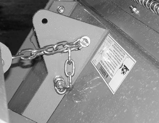
3. Lift rear deck to take tension off rear lift chains.
4. Remove 3/8 bolts, washers, and nuts from both rear lift chains. See Figure 25. This hardware is for factory shipping purposes only and can be discarded.
Attach Hydraulic Hoses
Air in hydraulic systems can cause erratic operation and allows loads or equipment components to drop unexpectedly. When connecting equipment or hoses or performing any hydraulic maintenance, purge any air in hydraulic system by operating all hydraulic functions several times. Do this before putting into service or allowing anyone to approach the equipment.
Attach the mower hydraulic hose to the tractor port. Hydraulic quick coupler is not supplied.
NOTE: The mower hydraulic system should have been filled at the factory. Always assume it is empty. Fully purge air and fill the hydraulic system by raising and lowering wings several times while hooked to a tractor hydraulic supply. Keep all personnel away while raising and lowering.
Optional Equipment
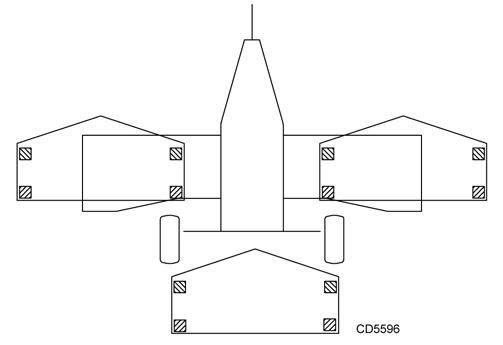
Light Kit Installation
1. Light, 4 Pin Right
2. Light, 4 Pin Left
3. Light Bracket
4. Blank .16 x 4.00 x 4.00
5. Wire Harness
6. 3/8 NC x 3-1/2 HHCS
7. 3/8 NC Flange Lock Nut
8.1/4 NC x 1 HHCS
9. 1/4 NC Lock Nut
Figure 27
10. #10 x 1/2 Tapping Screw
11. 34” Cable Tie
Light Kit Installation
1. Install wire harness (5) to bracket on trailer frame using #10 screws (10).
2. Route wires as shown. Be sure wire labeled “Left” is routed to the left side of the unit. Wrap excess wire around rear deck frame tubes as shown.
3. Clamp brackets (3) to rear deck frame tubes using blanks (4), 3/8 bolts (6) and nuts (7).

4. Secure left and right lamp (1 & 2) to brackets using 1/4 bolts (8) and nuts (9).
5. Connect light to wiring harness.
6. Pull any slack out of main wire and install cable ties (11) to rear hydraulic hose and trailer frame.
7. Extra slack in the light wires should be located near the wireing harness. Make sure wires cannot become entangled in driveline or hydraulic cylinder. Secure wires to frame tubes above cylinder and lock with cable ties.
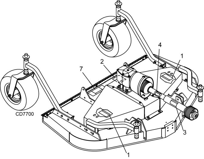
Rear Roller Kit Installation
5WPMAN0862 (11/22/2010)
1. Rear Roller
2. Rear Roller Bracket

3. 1/2 NC x 5-1/2 HHCS
4. 1/2 Flat Washer
5. 1/2 NC Flange Lock Nut
6. 3/8 NC x 1 Carriage Bolt
7. 3/8 NC Flange Lock Nut