11 minute read
DEALER SERVICE


The information in this section is written for dealer service personnel. The repair described here requires special skills and tools. If your shop is not properly equipped or your mechanics are not properly trained in this type of repair, you may be time and money ahead to replace complete assemblies.
Before working underneath, read manual instructions, securely block up, and check stability. Secure blocking prevents equipment from dropping due to hydraulic leak down, hydraulic system failure, or mechanical component failure.
Keep all persons away from operator control area while performing adjustments, service, or maintenance.
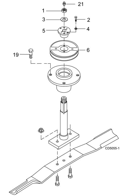
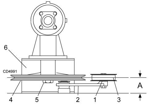
4. Disassemble split taper bushing (5) (located on top of pulley) by removing the two bolts (2) and washers (4).
5. Insert bolts (2) into the threaded holes of bushing flange.
6. Tighten bolts alternately to remove split taper bushing.
7. Remove pulley (6).
8. Remove bolts (19) that attach spindle to mower frame and remove spindle.
9. Remove grease fitting (21) from top of shaft.
Always wear relatively tight and belted clothing to avoid getting caught in moving parts. Wear sturdy, rough-soled work shoes and protective equipment for eyes, hair, hands, hearing, and head; and respirator or filter mask where appropriate.
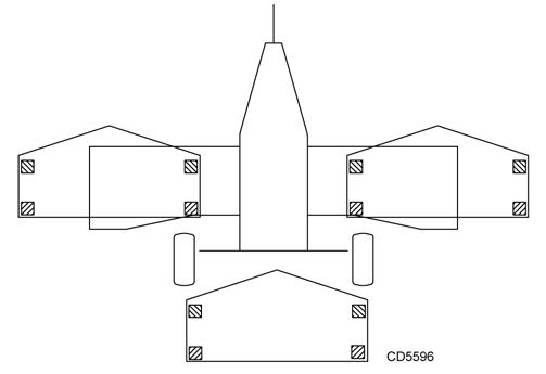
Blocking Method
NOTE: SEE BLOCKING METHOD, PG. 19
Blade Spindle Service
Spindle Repair
Spindle repair requires special skills and tools. If your shop is not properly equipped or your mechanics are not trained in this type of repair, you may be time and money ahead to use a new spindle assembly.
For reference, the grease fitting is in the top of the spindle shaft.
Permatex®1 3D Aviation Form-A-Gasket or equivalent is recommended as a sealant
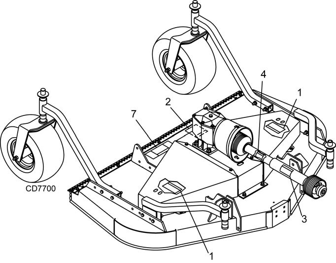
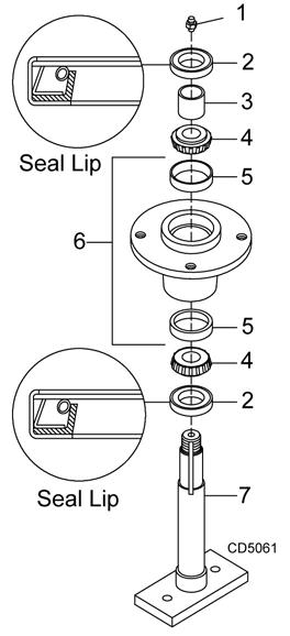
Spindle Removal (Figure 13)
1. Remove blade from spindle.
2. Remove belt from pulleys.
3. Remove jam nut (1) and washer (3) from top of spindle shaft.
1.Nut, jam 7/8 NF
2.Screw, HHCS 1/4 NC x 1 GR5
3.Washer, lock .929 x 1.66
4.Washer, lock 1/4
5.Bushing, H 1 straight bore w/key
6.Sheave, H 1 BK
19.Screw, HHCS 1/2 NF x 1-1/4 GR5
21.Grease fitting
Spindle Disassembly
1. Place spindle assembly in press and press shaft down through housing.
2. Remove seals from housing.
3. Remove bearing cups from housing by placing a punch in the slots provided and driving them out. Alternate punch positions from side to side. Take care to prevent housing damage.
Spindle Assembly (Figure 14)
■ Improper positioning of seals can cause seal damage. An improperly installed seal will leak and could cause bearing failure.
3. Place bottom bearing cone into spindle with taper positioned to mate with cup.
4. Identify the open side of the seal containing the spring.
5. Apply a thin coat of Permatex to the area of housing where seals seat.
6. Install bottom seal with spring up toward center of housing.
7. Place seal squarely on housing and select a piece of pipe or tubing with an OD that will set on outside edge of seal. A tubing with an OD that is too small will bow seal cage.
8. Carefully press seal into housing to prevent distortion to metal seal cage. Bottom seal should seat firmly and squarely against machined shoulder in housing.
9. Make sure seal lip did not roll under. Distortion to seal cage or damage to seal lip will cause seal to leak. Damaged seals must be replaced.
10. Insert shaft and bearing through bottom of housing.
11. Fill housing cavity with a medium grade grease.
12. Install top bearing on shaft to mate with top cone.
13. Apply a thin coat of Permatex to shaft area where sleeve will seat.
1.Grease fitting
2.Seal, 1.50 x 2.12 x .31
3.Sleeve, 1.14 x 1.50 x .55
4.Bearing cone
5.Bearing cup
6.Spindle housing
7.Shaft, blade spindle
Bearing cones and cups are designed to work together. It is important to position them so bearing cone taper mates with cup taper.
1. Lubricate new cups with a light oil. Place them in spindle housing so they will mate with bearing cones. Cups and cones are a press fit to minimize wear.
2. Seat cups securely with a press or place a large drift in the flat lip and drive them into housing until cup seats against machined shoulder of housing.
14. Install sleeve on shaft and press sleeve and bearing into housing until all free play is removed and there is a very light drag on bearings (similar to adjusting front wheel bearings on an automobile). Check by spinning spindle. It should turn freely.
15. Be careful not to overtighten bearings. Proper bearing adjustment is essential to good bearing life.
16. If you overtighten bearings, hold spindle housing and rap spindle shaft with a lead hammer.
17. Carefully press top seal in with spring up. Top seal should be flush with or to within 1/16" above the housing.
18. Rotate housing on spindle shaft, checking for free movement.
19. Install grease fitting in spindle shaft.
Spindle Installation NOTICE
■ Pulley installation sequence is very important for bearing life. Follow the sequence exactly.
1. Install spindle through bottom of mower and secure with four mounting bolts.
2. Install pulley and split taper bushing with integral key on spindle shaft. Make sure bushing is in contact with sleeve on spindle shaft.
3. Alternately tighten split taper bushing cap screws to 12 lbs.-ft.
4. Install toothed lock washer and nut on spindle shaft. Tighten nut until snug. Do not tighten this nut with wrench. Bearing damage will result from overtightening. Bend up edge of lock washer.
Gearbox Service
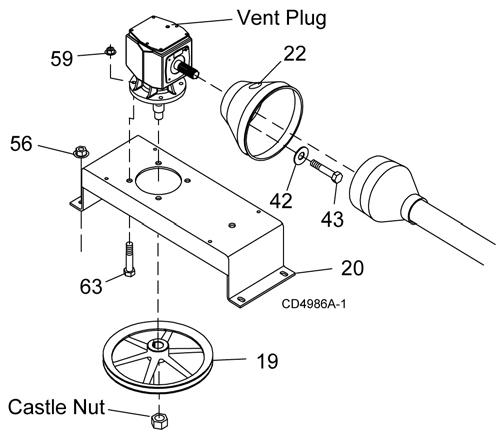
Gearbox Removal from Mower (Figure 15)
1. Disconnect and remove the rear driveline from the gearbox.
2. Remove vent plug and siphon gear lube from housing through this opening.
3. Remove gearbox stand (20) from mower deck by removing four flanged lock nuts (56).
4. Remove four cap screws (43) and washers (42) and remove shield (22) from gearbox.
5. Remove castle nut and hardware from output shaft of gearbox.
6. Remove sheave (19) from gearbox.
7. Remove four bolts (63) and lock nuts (59) that attach gearbox to gearbox stand and remove gearbox.
19.Sheave, offset 13.25 PD
20.Gearbox stand
22.Shield, counter cone
42.Washer, flat standard 5/16
43.Screw, HHCS 8mm x 1.25P x 16mm
56.Nut, flanged lock 1/2 NC
59.Nut, flanged lock 5/8 NC
63.Screw, flanged hex head 5/8 NC x 1-3/4
Gearbox Repair
Read this entire section before starting any repair. Many steps are dependent on each other.
Fill gearbox with SAE 80W or 90W gear lube until it runs out the side level plug.
Repair to this gearbox is limited to replacing bearings, seals, and gaskets. Replacing gears, shafts, and a housing is not cost effective. It is more economical to purchase a complete gearbox if repair to anything other than replacement of bearings, seals or gaskets is required.
Inspect gearbox for leakage and bad bearings.
Leakage is a very serious problem and must be corrected immediately.
Bearing failure is indicated by excessive noise and side-to-side or end play in gear shafts.
Seal Replacement
Recommended sealant for gearbox repair is Permatex Aviation 3D Form-A-Gasket or equivalent.
Leakage can occur at the vertical or horizontal gaskets and shaft seals.
Leakage at the horizontal gasket or seal can be repaired without removing the gearbox from the cutter.
Seal Installation
NOTE: Proper seal installation is important. An improperly installed seal will leak.
1. Clean area in housing where seal outer diameter (OD) seats. Apply a thin coat of Permatex.
2. Inspect area of shaft where seal seats. Remove any burrs or nicks with an emery cloth.
3. Lubricate gear shaft and seal lips.
4. Place seal squarely on housing, spring-loaded lip toward housing. Select a piece of pipe or tubing with an OD that will sit on the outside edge of the seal but will clear the housing. Tubing with an OD that is too small will bow seal cage and ruin seal.
5. Carefully press seal into housing, avoiding distortion to the metal seal cage.
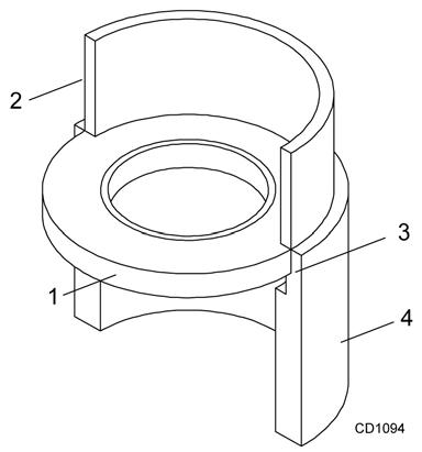
Incorrect Installation 1.Crown
1.Seal
2.Pipe or tube
3.Seal seat
4.Casting
NOTE: Pipe or tube must press at outer edge of seal.
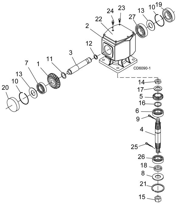
Vertical Shaft Repair (Figure 17)
1. Disconnect and remove the driveline from the gearbox.
2. Remove vent plug (24) and siphon gear lube from housing through this opening.
3. Remove gearbox stand from mower deck.
4. Remove gearbox and pulley from gearbox stand.
5. Remove vertical shaft seal (18). Replace with new seal (see Seal Replacement, page 29).
Vertical seal should be recessed in housing. Horizontal seal should be pressed flush with outside of housing.
NOTE: Distortion to seal cage or damage to seal lip will cause seal to leak.
6. Fill gearbox with SAE 80W or 90W gear lube until it runs out the level plug.
7. Assemble gearbox and pulley to gearbox stand. Attach gearbox stand to mower deck.
Horizontal Leak Repair (Figure 17)
1. Disconnect and remove the driveline from the gearbox.
2. Remove vent plug (24) and siphon gear lube from housing through this opening.
3. If the leak occurred at either end of horizontal shaft, remove oil cap (20) and/or oil seal (19). Replace with new one (refer to Seal Replacement, page 29).
4. Fill gearbox with SAE 80W or 90W gear lube until it runs out the level plug.
Gearbox Disassembly (Figure 17)
1. Remove top cover (22) from housing. Turn gearbox upside down and pour out remaining gear oil from gearbox.
2. Remove oil cap (20) (to be replaced).
3. Remove snap ring (10) and shim (13) from input shaft (3).
4. Support gearbox in hand press and push on input shaft (3) to remove bearing (7) and spacer (11).
5. Remove gear (1) from inside housing.
6. Remove oil seal (19) from front of housing (to be replaced).
7. Remove snap ring (10) and shim (13) from front of housing (2).
8. Remove input bearing (7) by using a punch and hammer from outside of housing.
9. Support housing in vise in a horizontal position.
10. The castle nut (15) and cotter pin (25) are already removed with the drive sheave. Remove the snap ring (21), washer (8), and seal (18).
11. Remove cotter pin (9), castle nut (14), and washer (8) from output shaft (4).
12. Remove output shaft (4) by using a punch and hammer and tap on top to drive down.
13. Remove gear (5) and shim (16) from inside housing.
14. Remove bearing (26) by using a punch and hammer from the top, outside the housing.
15. Support housing upside down (top cover surface) and remove bearing (6) by using a punch and hammer from the bottom side of the housing.
16. Inspect gears for broken teeth and wear. Some wear is normal and will show on loaded side. Forged gear surfaces are rough when new. Check that wear pattern is smooth.
17. Inspect vertical and horizontal shafts for grooves, nicks, or bumps in the areas where the seals seat. Resurface any damage with emery cloth.
18. Inspect housing and caps for cracks or other damage.
Gearbox Reassembly (Figure 17)
NOTE: Repair to this gearbox is limited to replacing bearings, seals, and gaskets. Replacing gears, shafts, and a housing is not cost effective. Purchasing a complete gearbox is more economical.
1. Clean housing, paying specific attention to areas where gaskets will be installed.
2. Wash housing and all components thoroughly. Select a clean area for gearbox assembly. Replace all seals, bearings, and gaskets. All parts must be clean and lightly oiled before reassembling.
3. Insert output bearings (6 & 26) in the housing, using a round tube of the correct diameter and a hand press.
4. Slide output shaft (4) through both bearings (6 & 26) until it rests against bearing (6).
5. Slide shim (16) over output shaft (4).
6. Press gear (5) onto output shaft (4) and secure with washer (17), castle nut (14), and cotter pin (9).
7. Apply grease to lower seal lips (18) and press seal over output shaft (4), using a tube of the correct diameter. Be sure not to damage the seal lip. Press in housing so that seal is recessed.
8. Insert protective washer (8) by hand. Install snap ring (21) and position it together with dual lip seal (18) by pressing it into position. Verify that snap ring is seated correctly.
9. Press bearing (7) into the housing, using a round tube of the correct diameter and a hand press. Secure with shim (13) and snap ring (10).
10. Secure snap ring (11) on input shaft (3) if not already secure.
11. Place gear (1) through top of housing and align gear (1) and gear (5) so that gear teeth are a match.
12. While holding gear (1) in place, slide input shaft (3) through gear (1) and bearing (7). Align splines on shaft (3) and gear (1).
13. Slide spacer (12) over input shaft (3) and press bearing onto input shaft (3), using a round tube of the correct diameter and a hand press.
14. Slide shim (13) over input shaft (3) and secure with snap ring (10).
15. Check input shaft end float by moving the input shaft (3) by hand. If end float is higher than 0.012”, insert shim between input shaft (3) and rear bearing (7). Repeat until end float is less than 0.012”. Check rotational torque by hand. The torque should be less than 2.2 lbs-inch.
16. Check that the gear backlash is between 0.006” and 0.016”. You should not have to adjust the backlash.
17. Press in input oil seal (19), using tube of correct diameter. Be careful not to damage seal lip.
18. Press oil cap (20) on to cover the rear of housing, using a tube of the correct diameter.
19. Check gearbox housing for leaks by plugging all holes except one. Apply 4 psi compressed air and immerse the gearbox in water to verify that there are no leaks.
20. Remove gearbox from water and dry off with compressed air. Add SAE 80W or 90W EP oil until it runs out of side level hole. Tighten all plugs.
Gearbox Installation
NOTE: Gearbox is heavy: do not attempt to move without mechanical assistance.
1. Set gearbox on gearbox stand and fasten with bolts and nuts. Torque bolts to 175 lbs-ft.
2. Attach drive sheave to output shaft. Secure using castle nut and hardware previously removed.
3. Attach gearbox stand to mower using four flanged lock nuts.
DRIVE SHEAVE INSTALLATION (FIGURE 18)
1. When gear stand is installed on mower, dimension A (from the top of the mower deck to the center line of the drive pulley) must be 2-7/16" (±1/32"). This is a critical dimension and must be carefully adjusted for proper belt life. Add or subtract shim washers under idler pulley to align with drive pulley.
2. Tighten gear stand hardware.
3. Fill gearbox half full with SAE 90W gear lube.
4. Check level after waiting five minutes to permit lube to work through bearings. Add lube, if necessary, until gearbox is half full.
5. Replace driveline shield. Attach driveline to gearbox.
1.Shim
2.Idler arm
3.Idler pulley
4.Drive sheave
5.Castle nut & cotter pin
6.Gearbox stand
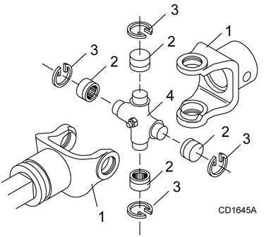
1.Yoke
2.Cup and bearing
3.Snap ring
4.Journal cross
U-Joint Disassembly
1. Remove external snap rings from yokes in four locations as shown in Figure 20.
Figure 20
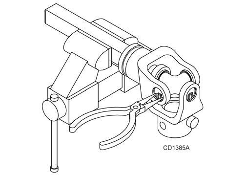
2. With snap rings removed, support drive in vise, hold yoke in hand and tap on yoke to drive cup up out of yoke. See Figure 21.
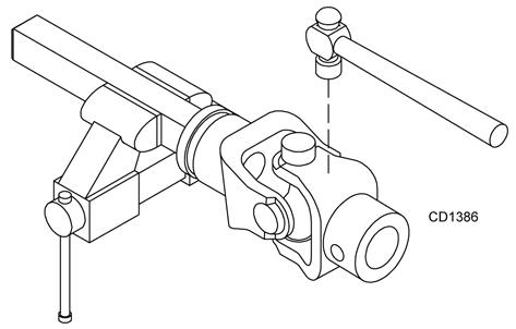
U-Joint Assembly
1. Place seals securely on bearing cups. Insert cup into yoke from outside and press in with hand pressure as far as possible. Insert journal cross into bearing cup with grease fitting away from shaft. Be careful not to disturb needle bearings. Insert another bearing cup directly across from first cup and press in as far as possible with hand pressure.
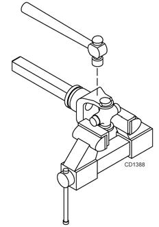
2. Trap cups in vise and apply pressure. Be sure journal cross is started into bearings and continue pressure with vise, squeezing in as far as possible. Tapping the yoke will help.
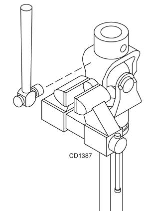
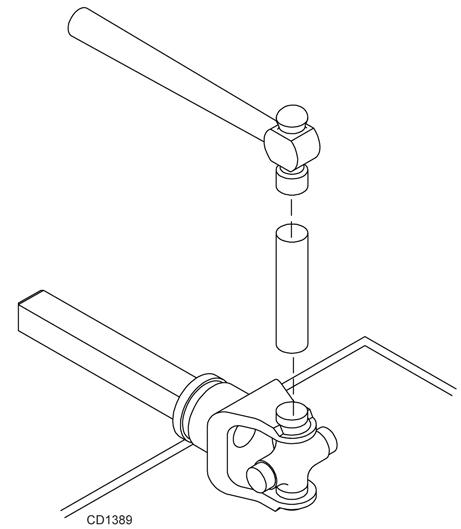
3. Clamp cup in vise as shown in Figure 22 and tap on yoke to completely remove cup from yoke. Repeat Step 2 and Step 3 for opposite cup.
3. Seat cups by placing a drift or socket (slightly smaller than the cup) on cup and rap with a hammer. See Figure 24. Install snap ring and repeat on opposite cup.
4. Repeat Step 1 and Step 2 to install remaining cups in remaining yoke.
5. Move both yokes in all directions to check for free movement. If movement is restricted, rap on yokes sharply with a hammer to relieve any tension. Repeat until both yokes move in all directions without restriction.
4. Place universal cross is vise as shown in Figure 23 and tap on yoke to remove cup. Repeat Step 3 for final removal. Drive remaining cup out with a drift and hammer.