3 minute read
Maintenance


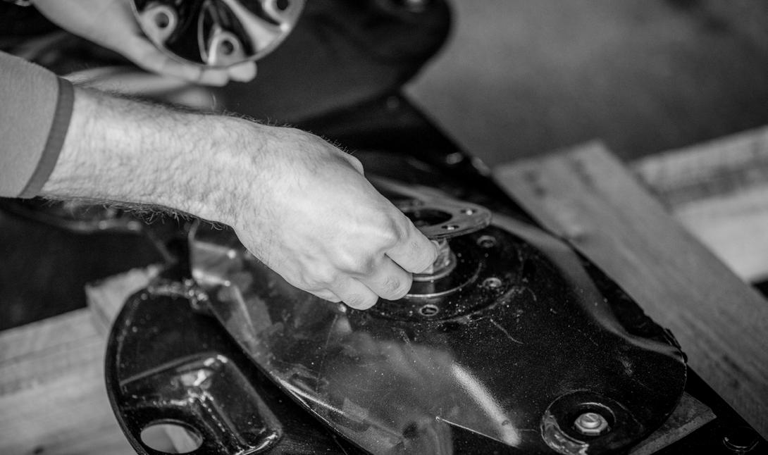
5. Replace the knife mounting disc unit onto the spindle. With this step you will reset the timing of the unit. Pay special attention to the orientation of the disc when replacing.
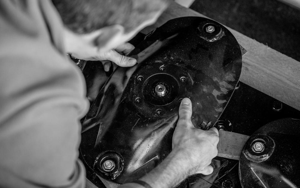
(Reference spindle diagrams on pg. 34)
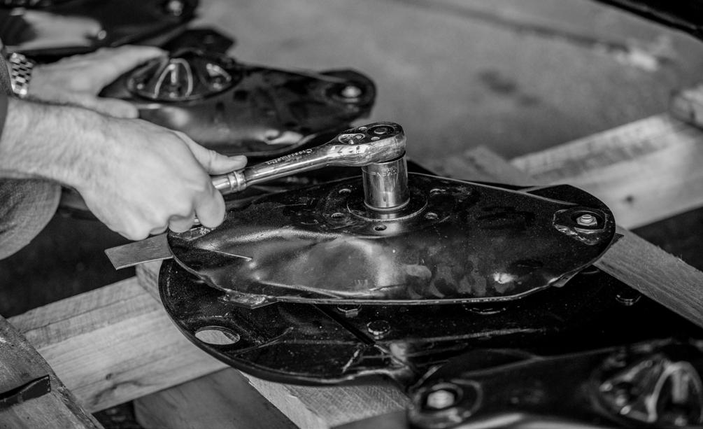
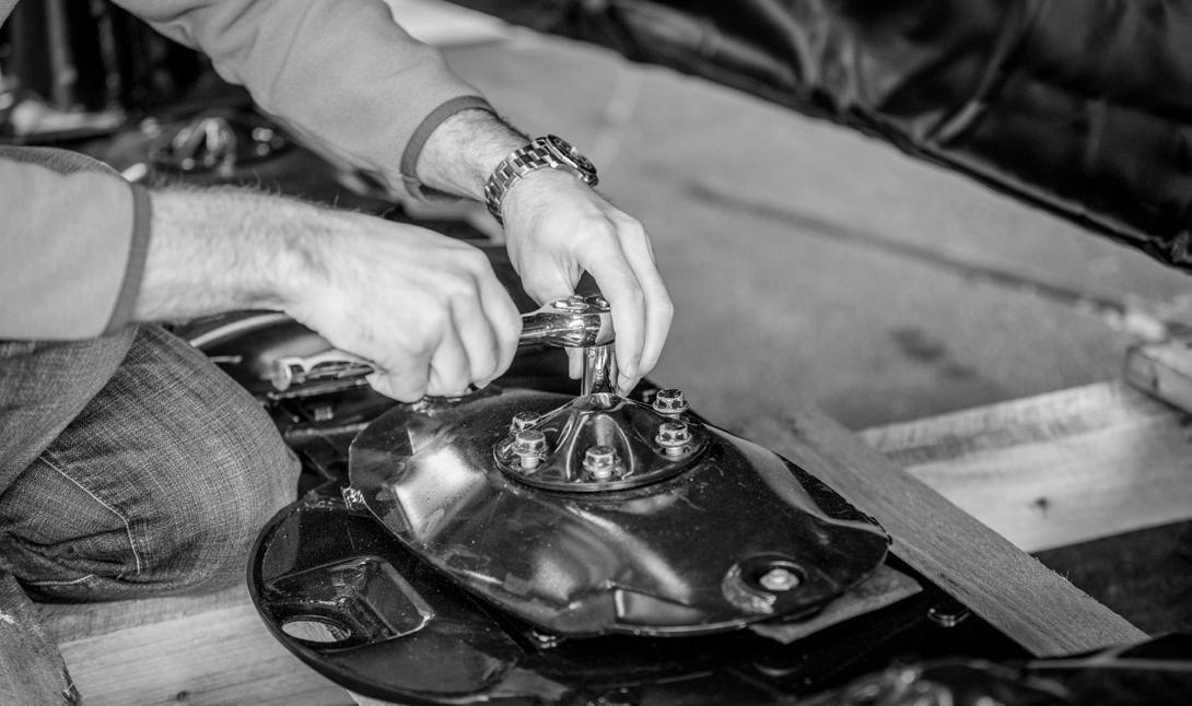
7. Next replace the spacer plate followed by the top cap. Tighten the 6 remaining bolts.
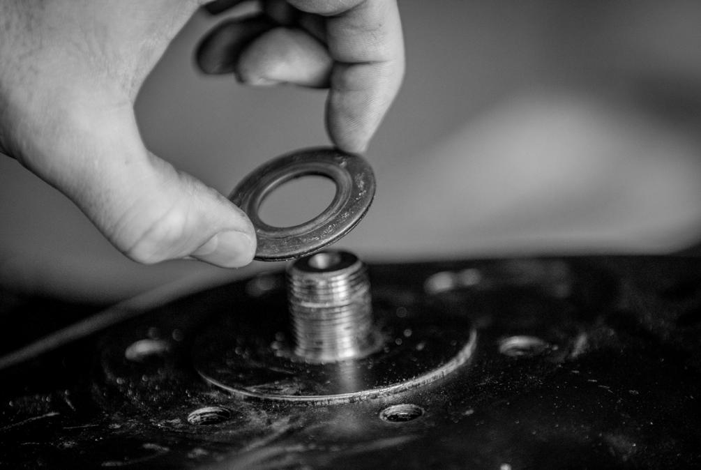
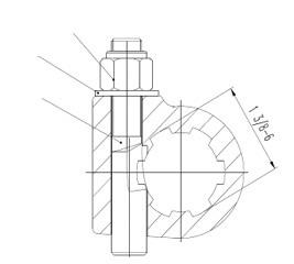
6. Place the large Belleville washer and retaining nut back on the spindle shaft and tighten. Pay special attention to the placement of the washer, place the washer so its cup points towards the bottom; it is designed this way to retain pressure on the assembly.
Spindle Diagram
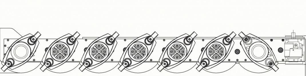
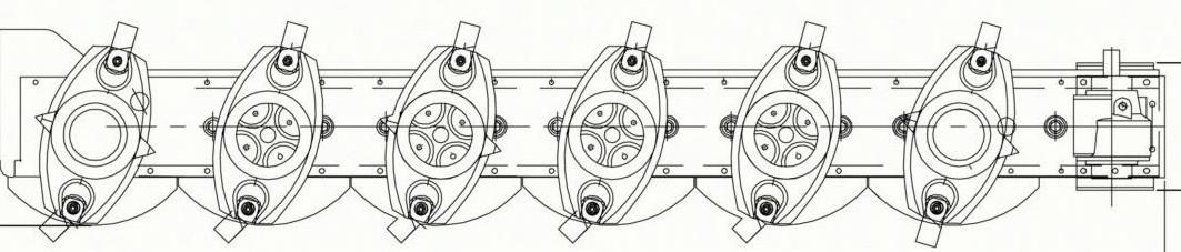
* Arrows on diagram below indicate the direction of rotation.
RH = Right Hand Knife
LH = Left Hand Knife
Practice Safe Service Procedures
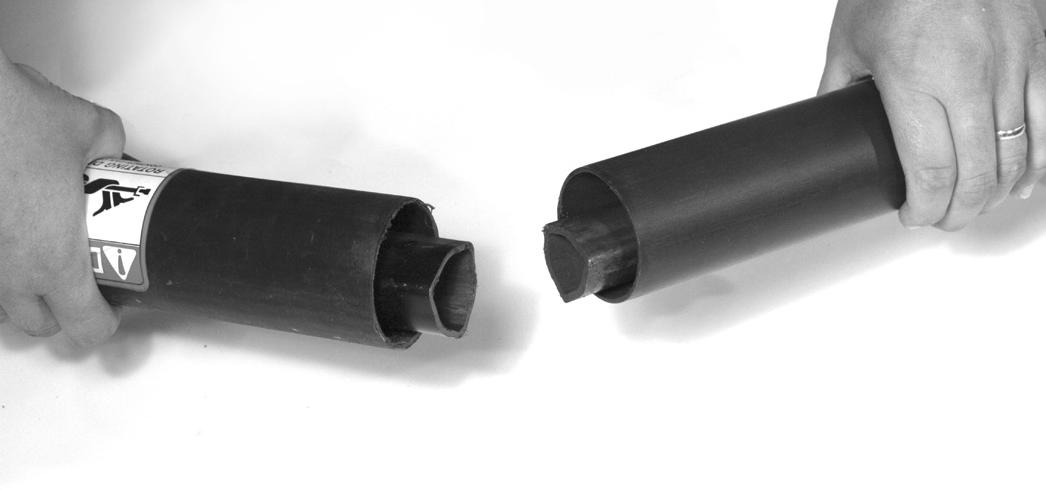
4. Slide shield collar back.
Caution
To help prevent personal injury caused by unexpected movement, be sure to service machine on a level surface.
Before servicing or adjusting machine connected to a tractor:
1. Lower machine to the ground.
2. Engage tractor parking brake and/or place transmission in “Park”.
3. Disengage PTO.
4. Shut off tractor engine and remove key.
5. Wait until all moving parts have stopped.
6. Disconnect PTO driveline from tractor.
The blades and blade holders may rotate after PTO is shut off. Look and listen for rotating driveline to stop before working on the mower.
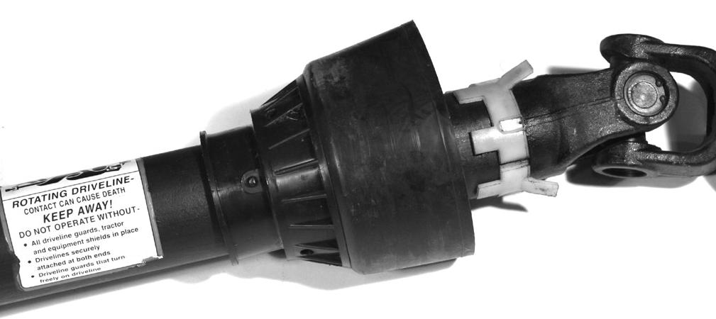
Disassembling Driveline Shield
1. Unhook driveline safety chain from one end of driveline.
2. Separate driveline into two (2) pieces.
5. If needed, separate white tab collar and slide shield tube back.
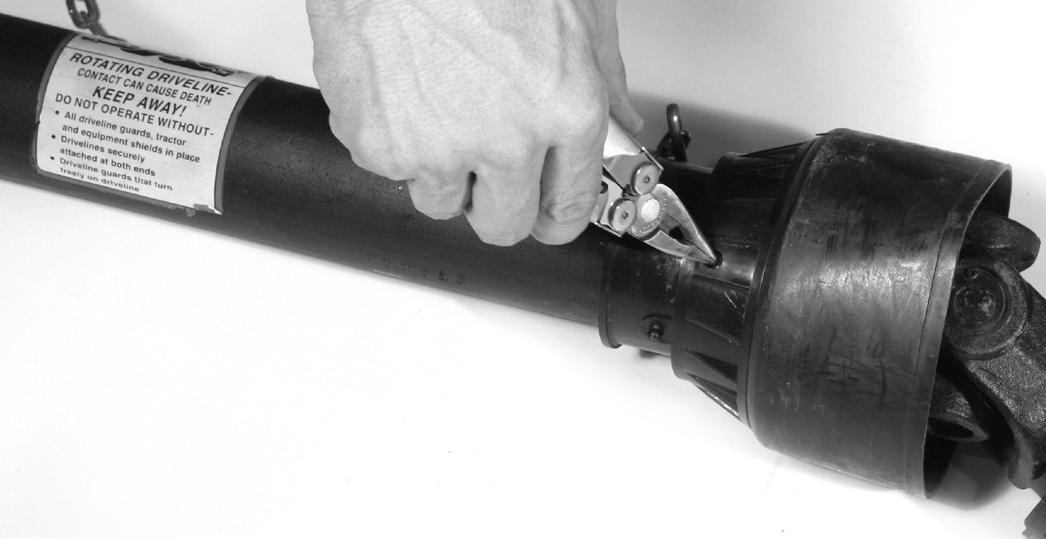
3. Using pliers, screwdriver or punch, depress white tabs in each of the release holes around the driveline shield. Driveline tab should “snap” somewhat when firmly depressed.
CAUTION
DO NOT operate PTO shaft without shielding installed.
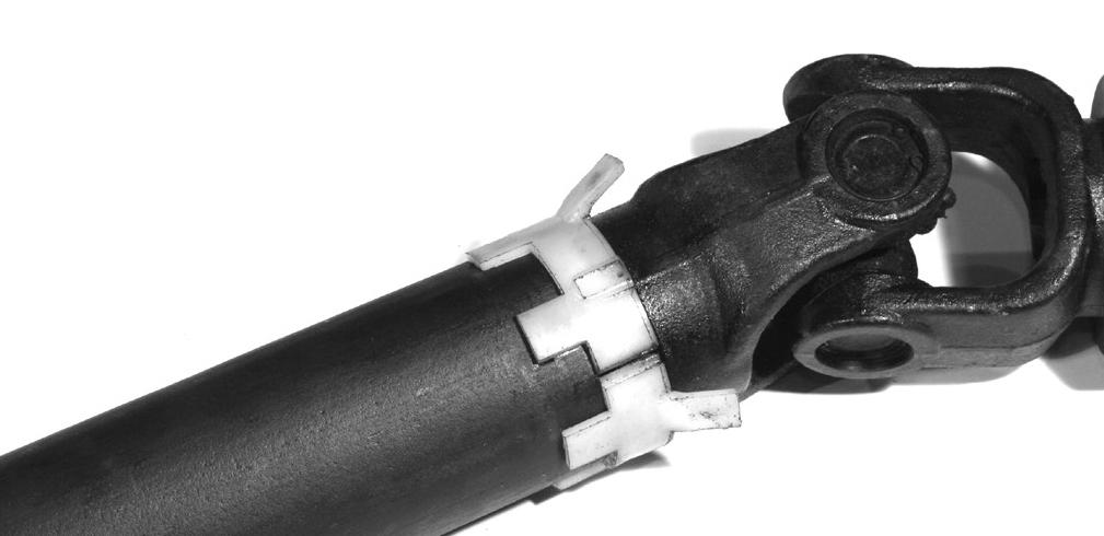
RE-ASSEMBLING DRIVELINE SHIELD
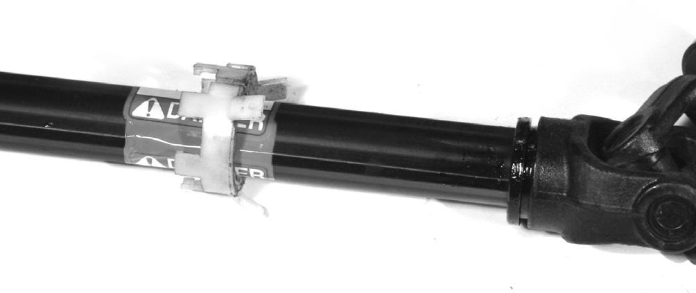
1. Replace white tabbed collar in groove of PTO shaft.
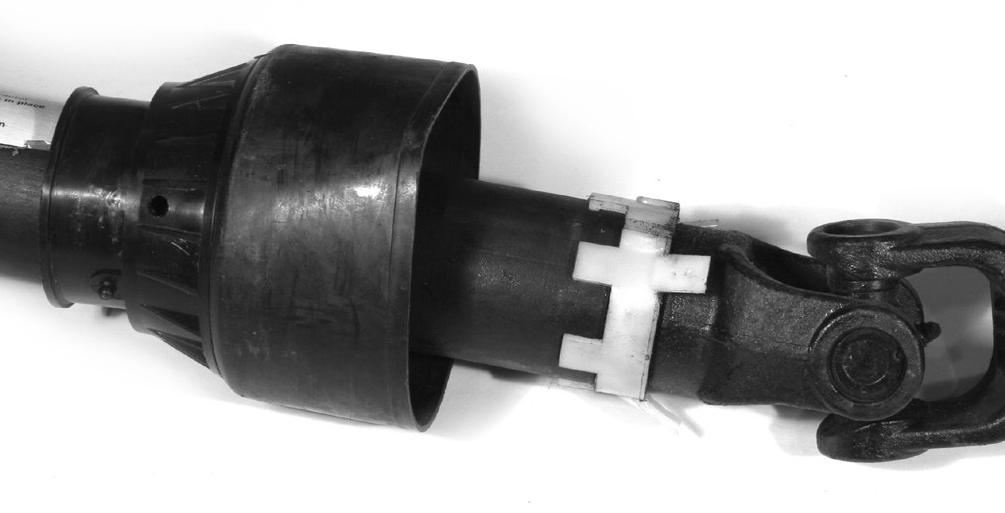
3. Slide universal joint cover up tube toward universal joint. Align grease fitting on shield with white square tabs on collars. This will properly align the position notch and all three (3) tabs.
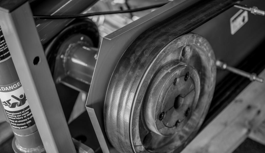
5. Pull carefully on the center of the belt to remove. It may be necessary to rotate the blade mounting discs on the cutter bar to get the pulleys to rotate and release the belt.
4. Slide collar shield into place until locked.
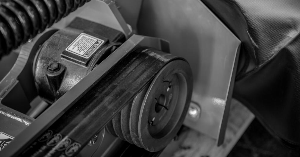
Drive Belt Replacement
When replacing drive belts, disconnect the PTO shaft from the tractor first. Use only Frontier Service belts available at your dealer. Part number (5TIDM411377)
1. Lower cutter bar to ground.


2. Disconnect PTO shaft from tractor.
3. Use a 19mm socket or wrench to remove the light kit. Then continue to remove the belt cover.
Be careful of pinch points between belts and pulleys

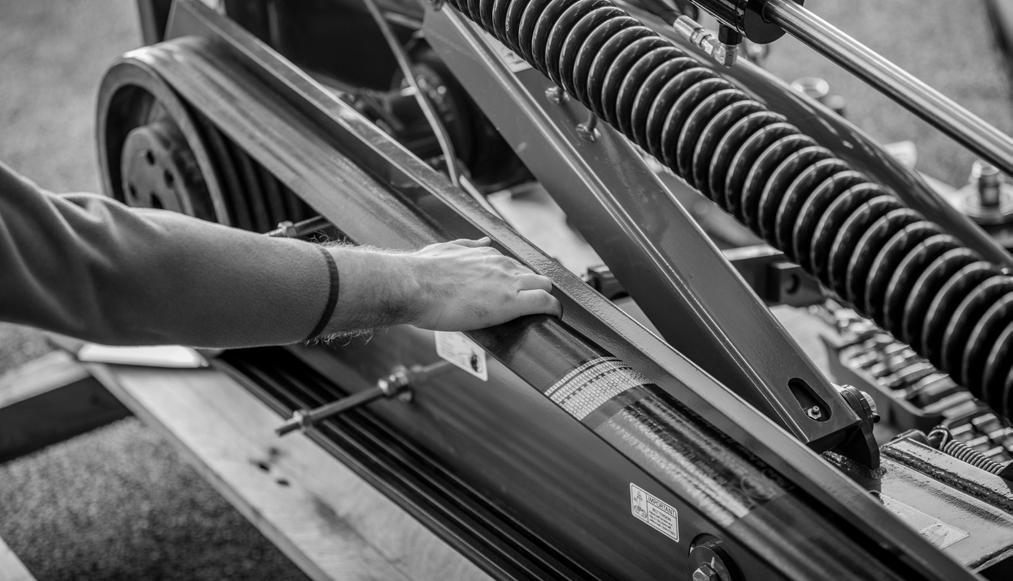
Putting On New Belts
1. Place the new belt on the smaller pulley first. Make sure all 4 grooves are properly aligned.
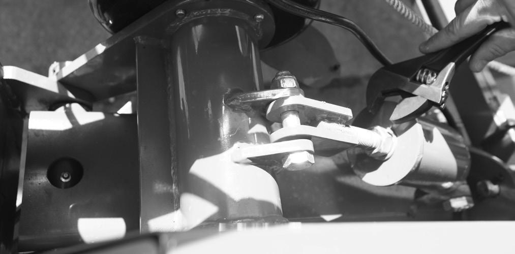
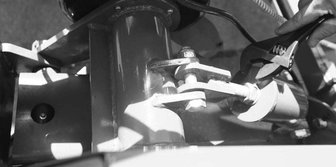
4. Loosen belt tension by adjusting the tensioner shown below. Make adjustments until drive belt is loose enough to remove from the pulley.
2. Start the belt on the larger pulley and pull on the top of the belt causing it to rotate around the pulley until all 4 grooves are properly aligned on the large pulley as well.
Service / Storage
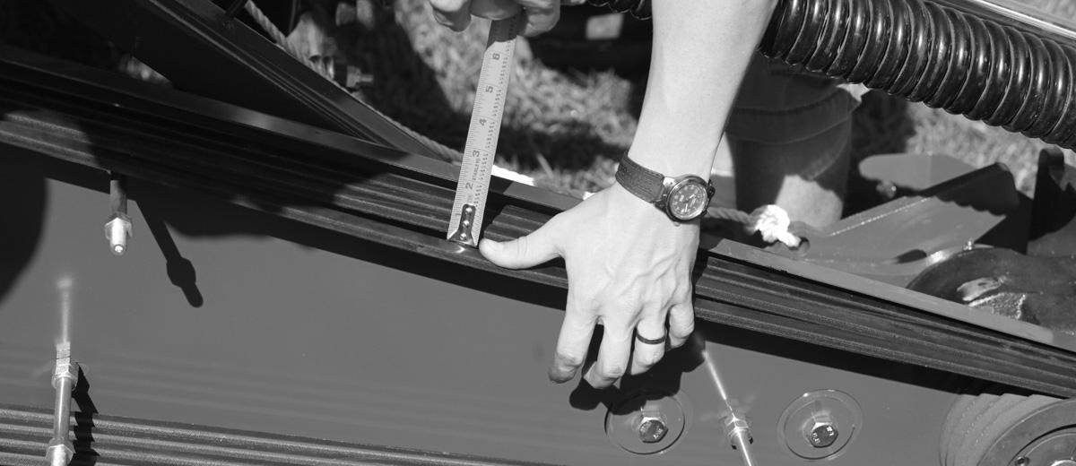
3. Retighten belt tension by adjusting the tensioner shown below. Belts should be tightened until 0.68” deflection occurs when applying 12 lbs. of force to the top of the belt. .
At The End Of Your Cutting Season
1. Drain and change the oil in the gearbox (fill plug) and cutter bar (breather cap on side of gear box).
2. Check (and replace where necessary) blades, bolts, and nuts on the mower.
3. Clean mower and touch up any rust spots that may have appeared.
4. Replace any safety decals if damaged.
5. Store with stand in proper lateral position.
6. Store disc mower in a clean dry location.
Always use a tractor to position equipment for storage. Never attempt to move equipment by hand.
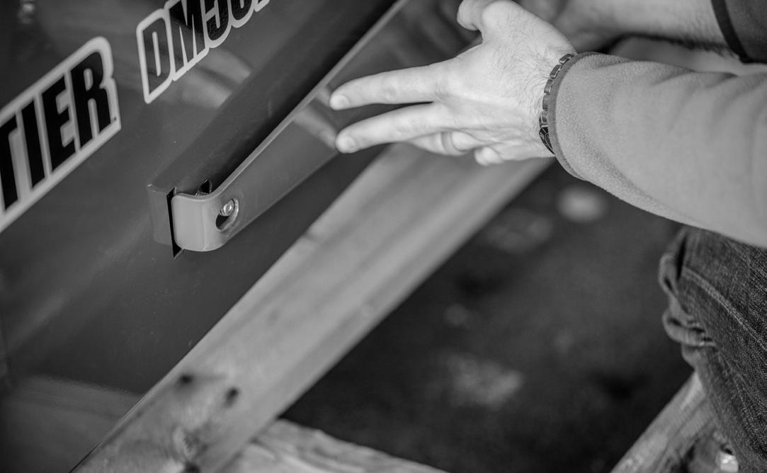
4. Replace the belt cover followed by the light bracket. Insure the light bracket is installed correctly by placing the tab into the slot on the belt cover as shown below. Retighten hardware and test run the unit.
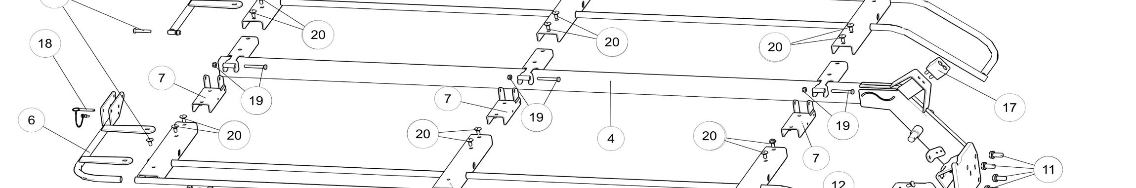
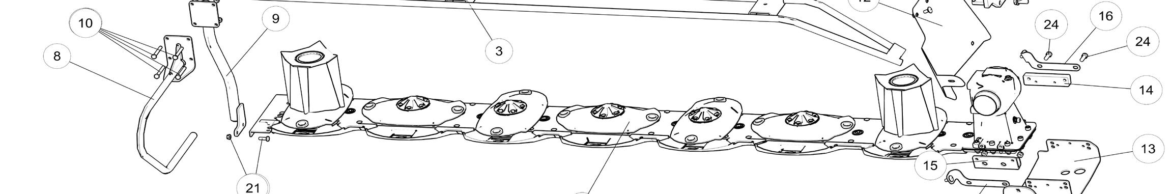
Parts
LVF0RZHU7UDFWRU(GRNH,FOXGHVUHI
LVF0RZHU&URVVHDULJV6DSULJVLFOXGHGSN
LVF0RZHU2XWHU3727XEHRNH
LVF0RZHU2XWHU3727XEH
LVF0RZHU2XWHUXDUG/RFNLJ&ROODU
LVF0RZHU7UDFWRU(G6KLHOG
LVF0RZHU2XWHU3727XEHXDUG
LVF0RZHU,HU3727XEHXDUG
LVF0RZHU,PSOHPHW(G6KLHOG
LVF0RZHU,HUXDUG/RFNLJ&ROODU
LVF0RZHU,HU3727XEH
LVF0RZHU,HU3727XEHRNH
LVF0RZHU2YHUUXLJ&OXWFKVVHPEO
LVF0RZHU/RFNLJ3L
LVF0RZHU7UDFWRU6LGH5ROO3L
LVF0RZHU,PSOHPHW6LGH5ROO3L
LVF0RZHU6DIHW&KDL
LVF0RZHU5RWDWLJULYHOLH6WLFNHU 7,0
LVF0RZHU/RFNLJROW 7,0
LVF0RZHUPP)ODWDVKHU 7,0
LVF0RZHUPP1OR,VHUW/RFN1XW 7,0
LVF0RZHU3726KDIW
7,0