UENR6390-01 May 2021
18
20
30
CONN 9
50
25
54
17 49
12
CONN 8
CONN 16
19
44
48
11 23
16
35
47
24
21
CONN 7
14
27
51
53
CONN 4
33
Component
Schematic Location
Machine Location
H-16
1
Module - Engine Control
E-16
38
Antenna - Communications
E-4
2
Motor - Alternator
I-13
39 40
Battery - 12 Volt #1
H-16
3
Motor - Starter
I-14
Battery - 12 Volt #2
H-16
4
Plugs - Glow
I-14
41
Bead - Ferrite
D-15
5
Radio - Communications
E-4
42
Bead - Ferrite
D-15
6
Receptacle - 12V Power Point
J-4
43
Block - Power Junction
I-14
7
Receptacle - Jump Start
I-15
44
Bus Bar - Unswitched Power +24V
H-13
8
Receptacle - USB 12V Power Only
J-4
45
Control - Machine
E-9
9
Relay - Auto Vibe
J-8
46 47
Converter - 24V to 12V
F-9
10
Relay - Brake 1
J-6
Fuse - 12V Converter
J-8
11
Relay - Brake 2
J-6
48
Fuse - Cab
J-8
12
Relay - Neutral 1
J-6
49
Fuse - Control
J-6
13
Relay - Neutral 2
Fuse - Engine Control Module
I-12
14
Relay - Glow Plugs
I-6
50
H-12
51
Fuse - Front Work Lights
J-6
15
Relay - Reverse Alarm
J-8
52
Fuse - Glow Plug
I-12
16
Relay - Shutdown
H-12
53
Fuse - Grade Control
I-8
17
Relay - Starter
I-12
54
Fuse - Grade Control 2
I-6
18
Relay - Switched 24V Power
J-8
55
Fuse - Horn
J-8
19
Resistor - Can 1 Terminal 1 (J1939)
E-12
56
Fuse - HVAC
J-6
20
Sender - Fuel Level Hi
H-16
57
Fuse - Ignition Wakeup
J-8
21
Sender - Fuel Level Low
H-16
58
Fuse - Machine
J-6
22
Sensor - Ambient Air Temprature
F-12
59
Fuse - Machine ECM and Beacon
J-8
23
Sensor - Axle Speed
D-10
60
H-12
24
Sensor - Hydraulic Temperature
D-12
61
Fuse - Product Link
I-8
25
Sensor - Water In Fuel (WIF)
F-12
62
Fuse - Rear Work Lights
J-6
26
Solenoid - Brake Release
E-10
63
H-12
27
Solenoid - Fan
E-12
64
Fuse - Shutdown Status
J-6
28
Solenoid - Valve Shift
D-11
65
Fuse - Vibe
I-6
29
Solenoid - Vibratory A (Fixed Frequency)
E-10
66
Fuse - Wipers
J-6
30
Solenoid - Vibratory A (Variable Frequency)
E-10
67
Ground - Engine 1
H-13
31
Solenoid - Vibratory B (Fixed Frequency)
E-10
68
Ground - Engine 2
I-13
32
Solenoid - Vibratory B (Variable Frequency)
E-10
69
Ground - Frame 1
H-14
33
Switch - Air Filter Restriction Pressure
E-12
70
Ground - Frame 2
Fuse - Shutdown
8
Machine Location
Alarm - Backup
Fuse - Main Power
CONN 15
Schematic Location
E-15
34
Switch - Disconnect
I-15
71
Ground - Panel
J-4
35
Switch - Hydraulic Filter Bypass Pressure
C-11
72
Ground - Rear Panel (Cab and Open Rops) Ground - Rear Panel (Open and Sun Canopy)
C-5 C-8
36 37
Switch - Neutral Start
F-10
73
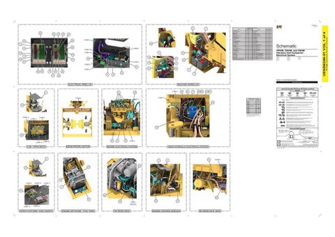
CP54B, CS54B, and CS64B Vibratory Soil Compactor Electrical System CP54B: G541-UP 5M41-UP 5051-UP
CS54B: GP51-UP PM51-UP 5061-UP
CS64B: TF61-UP 5181-UP
43 CONN 5 52
46
15
22 13
4
28
45 9
26
3
10
Volume 1 of 4: Main Electrical System PUBLICATIONS.CAT.COM
MACHINE WIRING GP
ELECTRICAL PANEL GP
Harness And Wire Electrical Schematic Symbols
41
2
CONN 4
39
56
63
73
68
69
66
Symbols
67 T
Pressure Symbol
CONN 5
CONN 6
Level Symbol
Flow Symbol
Circuit Breaker Symbol
Symbols and Definitions Connector Location - Volume 1 CONN 1
Schematic Location H-15
CONN 2
C-10
CONN 3
D-11
CONN 4
G-9
Connector Number
65 42
CONN 5
I-9
CONN 6
I-10
CONN 7 SERVICE TOOL
G-9
CONN 8
F-9
CONN 9
C-6 , C-9, J-4
CONN 10
B-4 , B-7
CONN 11
C-4 , C-7 , E-5
CONN 12
C-7
CONN 13
D-7
CONN 14
C-4
CONN 15
H-2
CONN 16
G-2
Fuse: A component in an electrical circuit that will open the circuit if too much current flows through it. Switch (Normally Open): A switch that will close at a specified point (temp, press, etc.). The circle indicates that the component has screw terminals and a wire can be disconnected from it. Switch (Normally Closed): A switch that will open at a specified point (temp, press, etc.). No circle indicates that the wire cannot be disconnected from the component. Ground (Wired): This indicates that the component is connected to a grounded wire. The grounded wire is fastened to the machine. Ground (Case): This indicates that the component does not have a wire connected to ground. It is grounded by being fastened to the machine. Reed Switch: A switch whose contacts are controlled by a magnet. A magnet closes the contacts of a normally open reed switch; it opens the contacts of a normally closed reed switch.
The connectors shown in this chart are for harness to harness connectors. Connectors that join a harness to a component are generally located at or near the component. See the Component Location Chart.
CONN 14
Temperature Symbol
Sender: A component that is used with a temperature or pressure gauge. The sender measures the temperature or pressure. Its resistance changes to give an indication to the gauge of the temperature or pressure.
T
CONN 9
Relay (Magnetic Switch): A relay is an electrical component that is activated by electricity. It has a coil that makes an electromagnet when current flows through it. The electromagnet can open or close the switch part of the relay.
CONN 11
Solenoid: A solenoid is an electrical component that is activated by electricity. It has a coil that makes an electromagnet when current flows through it. The electromagnet can open or close a valve or move a piece of metal that can do work. Magnetic Latch Solenoid: A magnetic latch solenoid is an electrical component that is activated by electricity and held latched by a permanent magnet. It has two coils (latch and unlatch) that make electromagnet when current flows through them. It also has an internal switch that places the latch coil circuit open at the time the coil latches.
72
Harness and Wire Symbols Wire, Cable, or Harness Assembly Identification: Includes Harness Identification Letters and Harness Connector Serialization Codes (see sample).
Harness Identification Letter(s): (A, B, C, ..., AA, AB, AC, ...)
L-C12 3E-5179
AG-C4 111-7898
36
L-C12 3E-5179
1
Part Number: for Connector Plug
Harness Connector Serialization Code: The "C" stands for "Connector" and the number indicates which connector in the harness (C1, C2, C3, ...).
Part Number: for Connector Receptacle
2 5A Plug
CONN 13
40
CONN 10
DRUM PROPEL MOTOR
CAB / OPEN ROPS
32
31
C0NN 2
ENGINE ELECTRICAL SYSTEM
MAIN HYDRAULIC ELECTRICAL SYSTEM
2 5
CONN 3
64
59
42
70 CONN 9
CONN 12
CONN 11 1
37 62 60 57 58
CONN 1
38
34
BELOW THE ENGINE MOUNT
CONN 13
CONN 10
OPEN PLATFORM / SUN CANOPY
ENGINE AIR INTAKE / FUEL TANK
RH REAR VIEW
ENGINE CONTROL MODULE
1 2
Deutsch connector: Typical representation of a Deutsch connector. The plug contains all sockets and the receptacle contains all pins.
1 2
Sure-Seal connector: Typical representation of a Sure-Seal connector. The plug and receptacle contain both pins and sockets.
Fuse (5 Amps)
9X-1123
Component Part Number
325-AG135 PK-14 Harness identification code: This example indicates wire group 325, wire 135 in harness "AG".
Wire Gauge* Wire Color
*Wire gauge is shown in AWG (American Wire Gauge) but could also be shown in metric denoted with mm
© 2021 Caterpillar. All Rights Reserved. CAT, CATERPILLAR, LET’S DO THE WORK, their respective logos, “Caterpillar Corporate Yellow”, the “Power Edge” and Cat “Modern Hex” trade dress as well as corporate and product identity used herein, are trademarks of Caterpillar and may not be used without permission.
61
6
Receptacle Pin or Socket Number
RH REAR AXLE VIEW
(Dimensions: 56 inches x 35 inches)
29
Component
42 Page,
55
Component Location - Volume 1
7
UENR6390-01 VOL 1 of 4
71