M0129107 April 2021
45
CONN 4
46
48
40
59
25
39
58
67 57
61
18
62
70
CONN 13
4
CONN 1 CONN 12
60
17 CONN 10
2 6
CS56B: S561438-UP 484276-UP
16 55 41
65
A
CONN 7
20
51 10
28
54
27 49
69 44 52
CONN 2
63
56
53
35
64
68
RH REAR CHASSIS VIEW
30
3
Connector Number CONN 1 CONN 2 CONN 3 CONN 4 CONN 5 CONN 6 CONN 7 CONN 8 CONN 9 CONN 10 CONN 11 - Diagnostic Connector CONN 12 CONN 13 CONN 14 CONN 15 CONN 16 CONN 17 CONN 18 CONN 19 CONN 20 CONN 21 CONN 22 CONN 23 CONN 94 CONN 95 CONN 96
42
47
CONN 3 VIEW OF AREA “A”
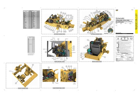
Volume 1 of 5: Chassis
(ROTATED FOR CLARITY)
PUBLICATIONS.CAT.COM
Harness And Wire Electrical Schematic Symbols Symbols
CONN 17 7
CONN 20
T
CONN 18
Pressure Symbol
Temperature Symbol
1
Level Symbol
Flow Symbol
Circuit Breaker Symbol
Symbols and Definitions Fuse: A component in an electrical circuit that will open the circuit if too much current flows through it. Switch (Normally Open): A switch that will close at a specified point (temp, press, etc.). The circle indicates that the component has screw terminals and a wire can be disconnected from it. Switch (Normally Closed): A switch that will open at a specified point (temp, press, etc.). No circle indicates that the wire cannot be disconnected from the component. Ground (Wired): This indicates that the component is connected to a grounded wire. The grounded wire is fastened to the machine. Ground (Case): This indicates that the component does not have a wire connected to ground. It is grounded by being fastened to the machine.
36 34
13
Reed Switch: A switch whose contacts are controlled by a magnet. A magnet closes the contacts of a normally open reed switch; it opens the contacts of a normally closed reed switch.
9
Sender: A component that is used with a temperature or pressure gauge. The sender measures the temperature or pressure. Its resistance changes to give an indication to the gauge of the temperature or pressure.
T
14
Relay (Magnetic Switch): A relay is an electrical component that is activated by electricity. It has a coil that makes an electromagnet when current flows through it. The electromagnet can open or close the switch part of the relay.
CONN 11 11
19
Solenoid: A solenoid is an electrical component that is activated by electricity. It has a coil that makes an electromagnet when current flows through it. The electromagnet can open or close a valve or move a piece of metal that can do work. Magnetic Latch Solenoid: A magnetic latch solenoid is an electrical component that is activated by electricity and held latched by a permanent magnet. It has two coils (latch and unlatch) that make electromagnet when current flows through them. It also has an internal switch that places the latch coil circuit open at the time the coil latches.
CONN 23
Harness and Wire Symbols
23 Wire, Cable, or Harness Assembly Identification: Includes Harness Identification Letters and Harness Connector Serialization Codes (see sample).
22
CONN 22 CONN 19
29 CONN 14
REAR CHASSIS VIEW
43 32 71
33
12
5 CONN 95
CONN 8
31
CONN 94 CONN 96
MAIN POWER PANEL VIEW
L-C12 3E-5179
Harness Connector Serialization Code: The "C" stands for "Connector" and the number indicates which connector in the harness (C1, C2, C3, ...).
Part Number: for Connector Receptacle
2 5A Plug
21
REAR CAB WALL VIEW
L-C12 3E-5179
1
37
24 CONN 16 CONN 15 CONN 21
Harness Identification Letter(s): (A, B, C, ..., AA, AB, AC, ...)
AG-C4 111-7898 Part Number: for Connector Plug
FRONT CHASSIS VIEW
CS68B: CS8119-UP 488179-UP
8
CONN 6
LH REAR CHASSIS VIEW
The connectors show n in this chart are for harness to harness connectors. Connectors that join a harness to a component are generally located at or near the component. See the Component Location Chart.
50
CS66B: 487684-UP
CP68B: 489107-UP
Connector Location - Volume 1 Schematic Location C-15 E-10, D-10 D-10 B-10 I-8 H-8 H-8 H-8 A -7 B-7 E-7 F-7 F-7 F-7 C-3 C-3 E-1 E-1 F-1 G-1 G-1 G-1 H-1 B-15 I-12 I-12
CP56B: P56862-UP 485113-UP
66
CONN 5
38
CS56B, CP56B, CS66B, CS68B and CP68B Vibratory Soil Compactor Electrical System
Receptacle Pin or Socket Number
1 2
Deutsch connector: Typical representation of a Deutsch connector. The plug contains all sockets and the receptacle contains all pins.
1 2
Sure-Seal connector: Typical representation of a Sure-Seal connector. The plug and receptacle contain both pins and sockets.
Fuse (5 Amps)
9X-1123
Component Part Number
325-AG135 PK-14 Harness identification code: This example indicates wire group 325, wire 135 in harness "AG".
Wire Gauge* Wire Color
*Wire gauge is shown in AWG (American Wire Gauge) but could also be shown in metric denoted with mm
© 2021 Caterpillar. All Rights Reserved. CAT, CATERPILLAR, LET’S DO THE WORK, their respective logos, “Caterpillar Corporate Yellow”, the “Power Edge” and Cat “Modern Hex” trade dress as well as corporate and product identity used herein, are trademarks of Caterpillar and may not be used without permission.
(Dimensions: 56 inches x 35 inches)
Sender - Fuel Lev el (High) Sender - Fuel Lev el (Low ) Sens or - A mbient A ir Temprature Sens or - A mmonia Sens or - A TTA C A ir Temperature Sens or - A x le Speed Sens or - Drum Speed Sens or - Hy draulic Temperature Sens or - Pre DOC Temperature Sens or - Pre SCR Temperature Sens or - Speed Sens or - Tailpipe Out NOX Sens or - Turbo Out NOX Sens or - V ibe Tac hometer Sens or - Water In Fuel Solenoid - A x le A Rev ers e Solenoid - A x le B Forw ard Solenoid - Blade A Solenoid - Blade B Solenoid - Brake Releas e Solenoid - Drum A Forw ard Solenoid - Drum B Rev ers e Solenoid - Fan Solenoid - V alv e Shif t Solenoid - V ibe A (STD) Solenoid - V ibe A (V ariable) Solenoid - V ibe B (STD) Solenoid - V ibe B (V ariable) Suppres s or - HV A C A rc Sw itc h - A /C Ref rigerant Pres s ure Sw itc h - A ir Filter Res tric tion Sw itc h - Battery Dis c onnec t Sw itc h - Hy draulic Filter By pas s V alv e - Coolant V LPM (24V )
26
42 Page,
A larm - Bac kup A lternator Battery - 1 & 2 Bloc k - Pow er Junc tion Bus s Bar Compres s or Gp Converter - 24V to 12V Diode - Starter Solenoid Control - DCU Control - Engine Control - Mac hine Fus e - A f tertreatment Fus e Bloc k A S 1 Fus e Bloc k A S 2 Glow Plugs Ground - A lternator Ground - Frame 1 Ground - Frame 2 Ground - Panel Ground - Starter Header - Tank Heater - DEF Line 1 (Suc tion) Heater - DEF Line 2 (Deliv ery ) Heater - DEF Line 3 (Return) Injec tor - DEF Module - A T ID Motor - A s c ent Lif t Pump Motor - Starter Port - 12V Pow er Receptacle - Auxiliary Start Relay - A T Pow er Relay - Glow Plug Relay - Shutdow n Res is tor - CA N Data Link Res is tor - CA N Data Link C1 Res is tor - CA N Data Link C2
Component
Schematic Machine Location Location H-16 37 H-16 38 F-11 39 B-9 40 C-11 41 D-9 42 I-7 43 D-11 44 B-8 45 46 B-8 B-6 47 B-9 48 C-10 49 F-7 50 D-11 51 E-8 52 E-8 53 H-7 54 H-7 55 E-8 56 E-8 57 E-8 58 F-11 59 D-9 60 D-8 61 D-8 62 D-8 63 D-8 64 A -6 65 SA -6 66 F-11 67 I-15 68 C-9 69 C-8 70 B-15 71
M0129107 VOL 1 of 5
Component
CONN 9
15
Component Location - Volume 1 Schematic Machine Location Location H-16 1 I-13 2 I-16 3 I-14 4 I-12 5 A -6 6 D-7 7 J-13 8 D-16 9 G-16 10 D-7 11 I-12 12 I-6 13 I-14 14 J-14 15 I-13 16 H-14 17 F-14 18 D-16 19 I-13 20 C-8 21 C-8 22 C-8 23 C-8 24 B-9 25 C-10 26 C-11 27 I-13 28 H-1 29 I-15 30 B-15 31 H-12 32 I-12 33 D-11 34 D-11 35 D-11 36