Wire Description
Power Circuits
43
3
57
12
56
11 14
55
113
10
51
13
53 52
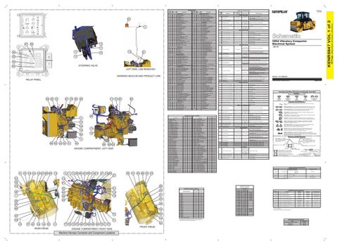
STEERING VALVE
54
LEFT SIDE, CAB REMOVED WARNING BEACON AND PRODUCT LINK RELAY PANEL
25
19
67
50
76
49
117 121 20
82
101
RD
Unswitched Battery (+)
632
WH
Fog Lamp - Left
YL
Horn Relay Circuit
645
PK
Hid Switch To HID Relay
105
BR
Key Switch
646
OR
Switch To Front Flood Lamps Relay
106
WH
Product Link Circuit
647
GN
Switch To Rear Flood Lamps Relay
BU
Radio Fuse
652
YL
Flood Lamp - Right Front
109
RD
Alternator Output (+)
653
GN
Flood Lamp - Left Front
690
GN
110
GN
+12v Key Switch On (protected)
111
YL
Steering Shunt Valve
112
PU
Main Power Relay Output
721
BR
Propel Mode 1
115
PK
Flasher Circuit
723
OR
Propel Mode 2
BR
Light Circuit
777
PU
Parking Brake
118
GY
Rear Washer Wiper Fuse
799
WH
Sensor Power 1, Switched Battery
119
PK
Front Washer Wiper Fuse
A784
YL
Vibrator Guage Input
123
WH
Switched Battery (+)
C701
YL
Parking Brake N.O.
124
GN
Heater Fuse
C728
YL
Edge Cutter Up
125
OR
Front Fan
C729
BU
Edge Cutter Up Solenoid
134
YL
Auxiliary Port (+)
C730
BR
Edge Cutter Down Solenoid
140
BU
Steering Sensor (+)
C744
PU
Parking Brake N.C.
144
GN
Warning Beacon Circuit
E761
BU
Warmup Valve
147
PU
Cab Circuit
F711
GN
ECM Can 1 (+)
160
PU
From Glow Plug Circuit Breaker
F712
GY
ECM Can 1 (-)
176
OR
Record Module Fuse
H750
BR
Drum Offset CW
177
RD
Main Circuit Breaker #1 Output
H751
OR
Drum Offset CCW
179
BU
Tach +12v
H752
YL
Encoder 1
181
RD
Engine Speed Control
H753
BU
Encoder 2
183
GY
Armrest Machine ECM Power Supply (+)
H764
GY
Steering Position Sensor - Rear
184
BU
Main ECM Power Supply (+)
H765
WH
Steering Postion Sensor - Front
186
WH
Auxiliary Circuit
J704
BU
Right Front Split Drum Valve
190
PK
Test Mode, Switched Battery
J706
OR
Left Rear Split Drum Valve
199
OR
Pot +V
J708
GN
Right Rear Split Drum Valve
200
BK
Ground Circuits
J711
PK
Right Rear Speed Sensor Signal
Main Chassis
J714
GY
Left Front Split Drum Valve
206
BK
Unused
J717
BU
Left Front Speed Sensor Signal
239
BK
Sensor (5v) Return
J718
OR
Right Front Speed Sensor Signal
A235
BK
5v Return
J720
BR
Left Rear Speed Sensor Signal
A249
BK
Can 1 Sheild
K708
BU
Handle Sensor 1
C234
BK
Sensor (5v) Return
K709
GY
Handle Sensor 2
Basic Machine Circuits
K725
GN
Propel Reverse
304
WH
Starter Relay #1 Output
K726
BU
Propel Forward
307
OR
Key Switch To Starter Relay Coil
N709
PK
Encoder 3
18 80 4 88 83
23 22
21
45
89
68 69
ENGINE COMPARTMENT, LEFT SIDE
41
35 102 104 103 61 66 65
5
112
7
8
26 84 87 86 114 115
47 116 28
59
121
64
96
33
CP_BrkSw_Flt
Possible Causes
Level 3 Fault
Both inputs are NOT complementary
CP_PropHndl_Flt
Level 3 Fault
Either PWM signal is less than 5% or greater than 96% for more than 250ms.
CP_PropHndl_Cal_Flt
Level 1Fault
Propel Handle calibration was not completed within 2 minutes.
CP_SpdCtrl_Flt
Level 2 Fault The ASC shall default to 50%
Propel Handle
1-6
Propel Handle Calibration
1-3
Auto Speed Control
1-7
Auto Speed Control Calibration
CP_SpdCtrl_Cal_Flt
Level 1 Fault
4-7
Propel Mode Switch
CP_Prop_Mode_Flt
Level 2 Fault System defaults to "Low" Propel mode
YL
Main Power Relay Coil
N710
PU
Encoder 4
BR
Backup Alarm Lamp / Travel Alarm
T749
YL
Friction Pack
322
GY
Horn Relay To Horn Switch
U717
OR
Hydrostatic Braking
330
YL
Neutral Light
X754
GN
Rear CCW Valve
376
GN
Start Switch To Start Aid Relay
X755
WH
Front CW Valve
384
BU
Glow Plugs
A892
OR
Vari Vibe Pot
Signal is out of range for more than 250ms. Auto Speed Control calibration was not completed within 2 minutes. Both inputs are open for more than 500ms.
PROPEL OUTPUT FAULTS 1-4
Forward Propel Solenoid
CP_Fwd_Vlv_Flt
Level 3 Fault
Solenoid is open, shorted to battery, or shorted to ground for more than 250ms.
1-8
Forward Propel Solenoid
CP_Fwd_Vlv_Cal_Flt
Level 1 Fault
Forward Propel Solenoid calibration was not completed within 2 minutes between 300 and 550mA.
1-5
Reverse Propel Solenoid
CP_Rvs_Vlv_Flt
Level 3 Fault
Solenoid is open, shorted to battery, or shorted to ground for more than 250ms.
1-9
Reverse Propel Solenoid
CP_Rvs_Vlv_Cal_Flt
Level 1 Fault
Reverse Propel Solenoid calibration was not completed within 2 minutes between 300 and 550mA.
4-8
Brake Solenoid
CP_Brake_Sol_Flt
Level 3 Fault
Solenoid is open, shorted to battery, or shorted to ground for more than 250ms.
Level 3 Fault
Solenoid is open, shorted to battery, or shorted to ground for more than 250ms.
4-9
Propel Shunt solenoid
CP_Shunt_Vlv_Flt
STEER INPUT FAULTS
2-1
2-3
308
2-6
2-4
A305
YL
Relay To Warning Horn(s)
C850
BR
Amp Vibe Signal To Recording Module
A309
GY
Fuel Enable/ Product Link (Switched Bat +)
C851
YL
Speed Signal
C852
BU
Inverted Speed Signal
2-7
Steering Mode Switch
Drum Offset Switch
Front Steering Sensor
Front Steer Sensor Calibration
Rear Steering Sensor
Rear Steer Sensor Calibration
J5R1-UP
Level 2 Fault Steering will default to "Coordinated" mode.
CP_Str_Mode_Flt
CP_Offset_Sw_Flt
Both inputs are open for more than 500ms.
Level 3 Fault
A steering Mode Switch fault (2-1) exists and a Drum Angle Sensor (2-3 or 2-4) fault exists.
Level 3 Fault
Both inputs are ON at the same time for more than 250ms.
Level 2 Fault System will change to Rear Steer mode.
CP_F_StrSnsn_Flt
CP_F_StrSnsn_Cal_Flt
Sensor is out of range or frequency for more than 250ms.
Level 3 Fault
Level 2 faults (2-3 and 2-4) exist on both Steering Sensors.
Level 1 Fault
Front Steer Sensor calibration was not completed within 2 minutes between 300 and 550mA.
Level 2 Fault System will change to Front Steer mode.
CP_R_StrSnsn_Flt
CP_R_StrSnsn_Cal_Flt
GN
Alternator 'R' Terminal
C853
GN
Signal Ground
YL
Hydraulic Oil Temperature Sensor
C855
GY
Edge Cutter Down Sw. To Main ECM
405
GY
Engine Oil Pressure Switch (low)
E803
YL
Rear CW Valve
406
PU
Water Temperature Switch
E804
BU
Front CCW Valve
Sensor is out of range or frequency for more than 250ms.
Level 3 Fault
Level 2 faults (2-3 and 2-4) exist on both Steering Sensors.
Level 1 Fault
Rear Steer Sensor calibration was not completed within 2 minutes between 300 and 550mA.
Level 2 Fault
Counts of one sensor are different by 2 or greater for 250ms. Counts of one sensor are zero or greater for 500ms.
2-5
410
WH
Fault Buzzer
H815
GY
Steer Mode 1
411
PK
Fault Light
H816
BU
Steer Mode 2
419
YL
Brake Light
J844
GY
Encoder ASC. Water
Steering Wheel Encoder
CP_Str_Whl_Flt
All four inputs are out of range (low/high) and Frequency equals 0 for 250ms.
Level 3 Fault
Quad count if opposite sign for more than 250ms. Level 2 faults on both sensors.
428
OR
Hydraulic Oil Temperature Switch
998
BR
Digital Sensor Return
447
PK
Fuel Level Gage
A914
OR
Ascs Pot
449
BU
Right Rear Spd Snsr Sgnl To Speedometer
A919
BU
Throttle Timer To Throttle Solenoid
465
OR
Low Charge Pressure Warning
A982
BR
Throttle Timer To Throttle Switch
A429
YL
Offset Guage
A983
BU
Throttle Timer To Throttle Solenoid
5-1
5-3
UCMD System
UCMD Cold Oil
CP_UCMD_Sys_Flt
CP_UCMD_ColdOil_Flt
Level 3 Fault
System senses motion, and the valve correlating to that direction is not ON for more than 250ms.
Level 3 Fault
System senses motion, and the valve correlating to that direction is not ON and Level 1 UCMD Log fault exists, and Cold Oil warning is present for more than 250ms.
B439
YL
Front Drum Vpm Sensor
A990
BU
Vibe Hi / Low Sw To Main ECM
5-2
UCMD Log
CP_UCMD_Log_Flt
Level 1 Fault
Any Logged UCMD System faults exist.
B440
GN
Rear Drum Vpm Sensor
C903
BU
Control To Water Pump 1 Relay
5-4
Cold Oil Warning
CP_Cold_Oil_Warn
Level 2 Fault
Hydraulic oil temperature is below 20°C (68°F)
C444
YL
Indicator - Alternator
C905
OR
Control To Water Pump 2 Relay
E455
BR
Hydraulic Oil Filter
C906
PU
Water Mode 1
C907
WH
Water Mode 2
BR
Wiper - Front (park)
C922
BR
Front Drum Water Pump
501
GN
Wiper - Front (low)
C923
OR
Rear Drum Water Pump
503
BR
Wiper - Rear (park)
C924
YL
Vibe Hi / Low Switch To Tachometer
504
YL
Wiper - Rear (low)
C925
GN
Vibe Hi / Low Switch To Tachometer
505
BU
Wiper - Rear (high)
C926
BU
Vibe Select Switch To Front Vibe
506
PU
Washer - Front
C927
PU
Vibe Select Switch To Rear Vibe
507
WH
Washer - Rear
C932
YL
Vibe Light
513
OR
A/C Refrigerant Pressure Switch
C933
GN
Auto / Manual Switch To Main ECM
521
YL
Fan Speed Switch To A/C Pressure Switch
C935
PU
Water Spray Light
536
WH
Hazard Switch To Turn Signal Switch
C936
GY
Spray Switch To Main ECM
537
GN
Turn Signal Switch To Flasher
J993
PK
Chip Spreader Sw.
A503
PK
Defroster Fan - Front (low)
K918
GN
Vibe Forward
A504
GN
Defroster Fan - Rear (low)
K919
YL
Vibe Reverse
A506
OR
Defroster Fan - Front (high)
L998
OR
Chip Spreader Out
N929
YL
Water Pot
603
PK
N957
PK
RXD - Comm 1
604
OR
Stop Lamps
N960
OR
TXD - Comm 1
605
YL
Turn Lamps - Left
N979
GN
Signal Ground - Comm 1
606
GY
Turn Lamps - Right
P978
GN
Vibe On / Off Switch
608
GN
Flood Lamps - Rear
P979
YL
Water On Switch
614
PU
Tail / Position / Dash Lamps
T969
YL
Test Mode
619
GN
Front Flood Lamps
T971
OR
Chipspreader Pot
631
GY
Fog Lamp - Right
Schematic Location
Machine Location
E-8
1
Component Radio Gp - Prod Link Radio
Schematic Location
Machine Location
A-2
51
B-8
2
Relay As - Front Work Lamps Relay 1
D-2
52
A-2
3
Relay As - Horn Relay 5
D-2
53
Battery Gp - 12V, 950-CCA
A-6
4
Relay As - Rear Work Lamp Relay 2
D-3
54
Circuit Breaker As - Alternator
B-6
5
Relay As - Vibe Gauge Relay 6
D-3
55
Circuit Breaker As - Cab
C-6
6
Relay As - Water Pump 1 Relay 3
D-2
56
Circuit Breaker As - Glow Plug
B-6
7
Relay As - Water Pump 2 Relay 4
D-2
57
Circuit Breaker As - Main
B-6
8
Sender As - Fuel Level
A-5
58
Coil - Solenoid, Chip Spreader
C-7
9
Sensor - Speed, Front Left
F-1
59
Coil - Solenoid, Front, CCW
D-7
10
Sensor - Speed, Front Right
E-1
60
Coil - Solenoid, Front, CW
D-7
11
Sensor - Speed, Rear Left
F-8
61
Coil - Solenoid, Hyd Warm
D-7
12
Sensor - Speed, Rear Right
D-8
62
Coil - Solenoid, Rear, CCW
D-7
13
Sensor As - Speed, Right Vibratory
E-1
63
Coil - Solenoid, Rear, CW
D-7
14
Sensor Gp - Position, Front Steering
F-2
64
Coil - Solenoid, Steer Shunt
D-7
15
Sensor Gp - Rear Steer
D-7
65
Coil Gp - Vibe Valve, Front
B-7
16
Sensor Gp - Speed, Rear Vibe
E-8
66
Coil Gp - Vibe Valve, Rear
B-7
17
Sensor Gp - Temperature, Hydr. Oil
A-6
67
Compressor Gp - Refrigerant
C-8
18
Solenoid - Forward Pump Control, Propel
A-7
68
ECM - Main Machine
F-4
19
Solenoid - Reverse Pump Control, Propel
A-7
69
Glow Plugs
A-7
20
Solenoid - Throttle
B-7
70
Ground - Engine, GS-02
A-8
21
Solenoid - Vibratory Pump Control
A-7
71
Ground - Engine, GS-05
A-7
22
Solenoid - Vibratory Pump Control
A-7
72
Ground - Frame GS 03
A-6
23
Supressor - Arc
B-7
73
Ground - Front, GS-04
E-2
24
Supressor - Arc, AC
C-8
74
Ground - Main 3, GS-32
A-6
25
Supressor - Arc, Shunt
C-7
75
Ground - Main, GS-31
E-7
26
Switch As - Hydraulic Oil Temperature
A-5
76
Ground - Main, GS-33
F-6
27
Switch As - Pressure, Engine Oil
A-8
77
Ground - Platform, GS-34
F-6
28
Switch As - Pressure, Hydraulic Oil
A-8
78
Ground - Rear, GS-01
E-8
29
Switch As - Pressure, Hydraulic Oil Filter
A-8
79
Horn As - 24V, Low To ne
E-1
30
Switch As - Pressure, Refrigerant High / Low
C-8
80
Jumper - CAN Resistor 1
E-2
31
Switch As - Temperature, Timing Advance
B-8
81
Lamp - Signal, Front Right
E-1
32
Switch As - Temperature, Water
B-8
82
Lamp - Signal, Left Front
F-1
33
Switch Gp - Disconnect, Battery
A-7
83
Lamp Gp - Flood, Left Front
F-1
34
Switch Gp - Glow Plug Relay
B-7
84
Lamp Gp - Flood, Left Rear
F-8
35
Switch Gp - Magnetic, HID Relay
B-7
85
Lamp Gp - Flood, Right Front
E-1
36
Switch Gp - Magnetic, Main Relay
B-7
86
Lamp Gp - Flood, Right Rear
D-8
37
Switch Gp - Starter Relay
A-7
87
Lamp Gp - License
E-8
38
Terminal As - Battery (Remote Jump Start, +)
A-6
88
Lamp Gp - Signal, Ext Left Rear
F-8
39
Valve - Solenoid, Brake
A-7
89
Lamp Gp - Signal, Ext Right Rear
C-8
40
Valve / Mnting Gp - Sol., Hydrostatic Braking
D-7
90
Lamp Gp - Signal, Left Rear
F-8
41
Valve As- -Sol.,Wtr Spray, Joint Cutter Opt.
F-1
91
Lamp Gp - Signal, Right Rear
D-8
42
Valve Gp - Solenoid, Cold Start, Timing Adv
C-8
92 93
Lamp Gp - Warning Beacon
F-7
43
Valve Gp - Solenoid, Fuel Shutoff
A-8
Module Gp - Throttle Timer
B-7
44
Valve Gp - Solenoid, Edge Cutter Dn
C-7
94
Motor Gp - Starter
A-7
45
Valve Gp - Solenoid, Edge Cutter Up
C-7
95
Panel Gp - Fuse
C-3
46
Valve Gp - Solenoid, Left Front Drum
F-1
96
Panel Gp - Relay
D-3
47
Valve Gp - Solenoid, Left Rear Drum
E-8
97
Pump Gp - Fuel Primary / Primary Filter
B-7
48
Valve Gp - Solenoid, Right Front Drum
F-1
98
Valve Gp - Solenoid, Right Rear Drum
E-8
99
A-5
49
A-5
50
CP_FCW_Vlv_Flt
Level 3 Fault
Solenoid is open, shorted to battery, or shorted to ground for more than 250ms.
Front Drum CW Steer calibration
CP_FCW_Vlv_Cal_Flt
Level 1 Fault
Front Drum CW Steer calibration was not completed within 2 minutes.
3-2
Front Drum CCW Steer Solenoid
CP_FCCW_Vlv_Flt
Level 3 Fault
Solenoid is open, shorted to battery, or shorted to ground for more than 250ms.
3-6
Front Drum CCW Steer calibration
CP_FCCW_Vlv_Cal_Flt
Level 1 Fault
Front Drum CW Steer calibration was not completed within 2 minutes.
3-3
Rear Drum CW Steer Solenoid
CP_RCW_Vlv_Flt
Level 3 Fault
Solenoid is open, shorted to battery, or shorted to ground for more than 250ms.
3-7
Rear Drum CW Steer calibration
CP_RCW_Vlv_Cal_Flt
Level 1 Fault
Front Drum CW Steer calibration was not completed within 2 minutes.
3-4
Rear Drum CCW Steer Solenoid
CP_RCCW_Vlv_Flt
Level 3 Fault
Solenoid is open, shorted to battery, or shorted to ground for more than 250ms.
3-1
Front Drum CW Steer Solenoid
3-5
CP_RCCW_Vlv_Cal_Flt
Level 1 Fault
Front Drum CW Steer calibration was not completed within 2 minutes.
Steering Wheel Friction
CP_Friction_Flt
Level 3 Fault
Solenoid is open, shorted to battery, or shorted to ground for more than 250ms.
Steering Shunt Solenoid
CP_Str_Shunt_Vlv_Flt
Level 3 Fault
Solenoid is open, shorted to battery, or shorted to ground for more than 250ms.
3-8
Rear Drum CCW Steer calibration
3-9 5-9
4-1
Alternator Gp - Charging
Pump Gp - Water, Front
Water Mode Switch
4-2
Water Spray Timer
4-3
Water Spray Timer calibration
Level 1 Fault System shall default to "Auto" mode
Both inputs are open for more than 500ms.
CP_Water_Tmr_Flt
Level1 Fault Timer shal ldefault to 100%
Signal is out of range for more than 500ms.
CP_Water_Tmr_Cal_Flt
Level 1 Fault
Water Spray Timer calibration was not completed within 2 minutes.
CP_Water_Mode_Flt
110
39
81
6-2
Vibe Forward Solenoid
CP_Vibe_High_Flt
Level 1 Fault
Open circuit when system is active. Short circuit when system is inactive.
6-3
Vibe Reverse Solenoid
CP_Vibe_Low_Flt
Level 1 Fault
Open circuit when system is active. Short circuit when system is inactive.
8-1
Chip Spreader Potentiometer
CP_CS_Pot_Flt
Level 1 Fault Timer shall default to 50%
8-2
Chip Spreader calibration
CP_CS_Pot_Cal_Flt
Level 1 Fault
Chip Spreader calibration was not completed within 2 minutes.
8-3
Chip Spreader Solenoid
CP_CS_Vlv_Flt
Level 1 Fault
Solenoid is open, shorted to battery, or shorted to ground for more than 250ms.
8-4
Edge Cutter Switch
CP_Edger_Sw_Flt
119
91
118
48
30
44
36
97 99
32 60
72
40
120 108
71 37
42
106
105
62
REAR DRUM
111
Temperature Symbol
Level 1 Fault
Both inputs are ON for more than 250ms.
7-1
Front Left Sensor
CP_AS_FL_Snsr_Flt
Level Symbol
Circuit Breaker Symbol
Flow Symbol
Symbols and Definitions Fuse: A component in an electrical circuit that will open the circuit if too much current flows through it. Switch (Normally Open): A switch that will close at a specified point (temp, press, etc.). The circle indicates that the component has screw terminals and a wire can be disconnected from it.
Ground (Wired): This indicates that the component is connected to a grounded wire. The grounded wire is fastened to the machine. Ground (Case): This indicates that the component does not have a wire connected to ground. It is grounded by being fastened to the machine. Reed Switch: A switch whose contacts are controlled by a magnet. A magnet closes the contacts of a normally open reed switch; it opens the contacts of a normally closed reed switch. Sender: A component that is used with a temperature or pressure gauge. The sender measures the temperature or pressure. Its resistance changes to give an indication to the gauge of the temperature or pressure.
Signal is out of range for more than 500ms. T
Relay (Magnetic Switch): A relay is an electrical component that is activated by electricity. It has a coil that makes an electromagnet when current flows through it. The electromagnet can open or close the switch part of the relay.
ANTI SPIN FAULTS
Solenoid: A solenoid is an electrical component that is activated by electricity. It has a coil that makes an electromagnet when current flows through it. The electromagnet can open or close a valve or move a piece of metal that can do work.
Front Left Drum reads 0 Km/h and other three drums read greater than1 Km/h.
Level 1 Fault
Front Left Drum input reads 1500mV - 3500mV for 500ms. 7-2
Front Right Sensor
CP_AS_FR_Snsr_Flt
Level 1 Fault
Front Right Drum reads 0Km/h and other three drums read greater than 1Km/h.
Level 1 Fault
Rear Left Drum reads 0 Km/h and other three drums read greater than1 Km/h.
Magnetic Latch Solenoid: A magnetic latch solenoid is an electrical component that is activated by electricity and held latched by a permanent magnet. It has two coils (latch and unlatch) that make electromagnet when current flows through them. It also has an internal switch that places the latch coil circuit open at the time the coil latches.
Front Right Drum input reads 1500mV - 3500mV for 500ms. 7-3
Rear Left Sensor
CP_AS_RL_Snsr_Flt
Rear Left Drum input reads 1500mV - 3500mV for 500ms. 7-4
Rear Right Sensor
CP_AS_RR_Snsr_Flt
Rear Right Drum reads 0Km/h and other three drums read greater than 1Km/h.
Level 1 Fault
Rear Right Drum input reads 1500mV - 3500mV for 500ms. 7-5
Front Left PWM
CP_AS_FL_Vlv_Flt
Level 1 Fault
Output is shorted to battery, grounded, or open.
7-6
Front Right PWM
CP_AS_FR_Vlv_Flt
Level 1 Fault
Output is shorted to battery, grounded, or open.
7-7
Rear Left PWM
CP_AS_RL_Vlv_Flt
Level 1 Fault
Output is shorted to battery, grounded, or open.
7-8
Rear Right PWM
CP_AS_RR_Vlv_Flt
Level 1 Fault
Output is shorted to battery, grounded, or open.
Harness and Wire Symbols Wire, Cable, or Harness Assembly Identification: Includes Harness Identification Letters and Harness Connector Serialization Codes (see sample).
Harness Identification Letter(s): (A, B, C, ..., AA, AB, AC, ...)
L-C12 3E-5179
AG-C4 111-7898
CP_AR_Snsr_Pwr_Flt
Hydraulic Temperature Sensor
CP_HydOil_Snsr_Flt
Level 1 Fault
Sensor is out of range.
5-8
Hydraulic Warm Up Solenoid
CP_WarmUp_Vlv_Flt
Level 1 Fault
Solenoid is open, shorted to battery, or shorted to ground for more than 250ms.
9-4
CAN Main Controller
CP_CAN_Rx_Flt
Level 3 Fault
Loose connection, open circuit, or short circuit on one or more of the CAN signals.
Side Console Sensor Power
5-7
L-C12 3E-5179
Part Number: for Connector Receptacle
2
Level 3 Fault Sensor Power : The 5V sensor voltage supply is out of range. A voltage below 4.75 or above 5.25 is detected.
9-1
Harness Connector Serialization Code: The "C" stands for "Connector" and the number indicates which connector in the harness (C1, C2, C3, ...).
1
Part Number: for Connector Plug
MISC. FAULTS Plug
Short to battery or ground.
Receptacle Pin or Socket Number
1 2
Deutsch connector: Typical representation of a Deutsch connector. The plug contains all sockets and the receptacle contains all pins.
1 2
Sure-Seal connector: Typical representation of a Sure-Seal connector. The plug and receptacle contain both pins and sockets.
5A Component Part Number
9X-1123
Fuse (5 Amps)
325-AG135 PK-14 Harness identification code: This example indicates wire group 325, wire 135 in harness "AG".
Wire Gauge Wire Color
Sender and Solenoid Specifications Component Description
Part No.
Connector Location - Volume 1
24
93
107
T
Pressure Symbol
272-0899
Coil - Solenoid
282-6944
Coil As
228-4109
Sender As
Resistance (Ohms)¹
Steering Valve : Front, CCW Front, CW Rear, CCW Rear, CW
5.6 ±2.5%
Vibe Valve : Front Rear
6.67 Empty : 240 - 250 Full : 28 - 33
Fuel Level
WIRES IN THE FOLLOWING GROUPS SHALL BE TWISTED: ONE TWIST PER 25 MM.
31
92
29
Symbols
¹ At room temperature unless otherwise noted.
98
1
Harness And Wire Electrical Schematic Symbols
34
100
38
Printed in U.S.A.
Switch (Normally Closed): A switch that will open at a specified point (temp, press, etc.). No circle indicates that the wire cannot be disconnected from the component.
27 101
© 2009 Caterpillar, All Rights Reserved
WATER / VIBE / CHIPPER / EDGER
Antenna As
Pump Gp - Water, Rear
Volume 1 of 2: Machine
STEER OUTPUT FAULTS
500
Rotary Beacon Lamp
CD54 Vibratory Compactor Electrical System
Quad counts are different by 2 for 250ms.
403 404
Alarm As - Backup
16
Park Brake Switch
1-2
2-2
321
Component
17
Description
Circuit Breaker To Light Switch Control Circuits
116
85
109
Fault Name in Software
Either PWM signal frequency is out of range
Component Location - Volume 1
74
Diagnostic
PROPEL INPUT FAULTS 1-1
108
Lighting Circuits
2
Flash Code
103
Accessory Circuits
58
Description
Lighting Circuits (Continued)
Monitoring Circuits
KENR5947 July 2009
Diagnostic Trouble Codes Wire Color
77 78 15 79 46 70 94 95 90 75
6
63
73
ENGINE COMPARTMENT, RIGHT SIDE
Machine Harness Connector and Component Locations
FRONT DRUM
Connector Number CONN 1
Schematic Location F-8
WIRE NAME
Machine Location
199-CN152
C234-CN219
239-F042
B439-F028
A249-M566
F711-M604
Off-Machine Switch Specification Part No.
A249-M570
F711-M606
F712-M613
F711-M605
F712-M614
C234-M506
H765-M623
CONN 2
F-8
101
A249-M567
CONN 3
F-8
102
C234-M503
CONN 4
F-8
103
A249-M571
F711-M610
F712-M617
CONN 5
E-8
104
A249-M572
F711-M609
F712-M616
C234-M507
H764-M622 F712-P396
CONN 6
D-8
105
CONN 7
D-8
106
A249-P347
F711-P389
CONN 8
D-8
107
199-P294
C234-P358
CONN 9
C-8
108
A235-P862
J844-P908 C234-P355 T749-P931
CONN 10
C-8
109
199-P289
CONN 11
A-8
110
200-P932
CONN 12
E-7
111
A235-P940
J844-P937
CONN 13
E-7
112
199-P864
C234-P863 J844-P936 F711-P390
CONN 14
F-7
113
A235-P311
CONN 15
C-6
114
A249-P349
CONN 16
B-6
115
A249-P351
CONN 17
F-5
116
A249-P353
CONN 18
A-4
117
A249-P352
F711-P388
F712-P395
118
199-P290
C234-P354
165-2521
Switch As - Pressure, Hydraulic Oil
1400 kPa
1100±75 kPa
203 psi
159±11 psi
134-0404
Switch As - Pressure, Hydraulic Oil Filter
275.8±27.6 kPa
207 kPa
40±4 psi
30 psi
114-5333
Switch As - Pressure, Refrigerant High/Low
215-6314
Switch As - Temperature, Hydraulic Oil
235-1790
Switch As - Temperature, Timing Advance
203-3219
Switch As - Temperature, Water
275 to 1750 kPa¹
-
(39.9 to 253.8 psi)
-
73.89±2.78° C
65.56° C
165±37° F
150° F
37 / 43° C
27 / 33° C
98.6 / 109.4 F
80.6 / 91.4° F
107±3° C
90° C
224.6±37.4° F
194° F
Normally Close A-C Normally Close A-B Normally Open Normally Open Normally Open² Normally Open Normally Close Normally Open
² Contact position at the contacts of the harness connector.
119
199-P293
C234-P357
120
B440-R067
C234-R051
The connectors shown in this chart are for harness to harness connectors. Connectors that join a harness to a component are generally located at or near the component. See the Component Location Chart.
10.2±3 psi
F712-P399
E-1
121
13.5±3 psi
F712-P401
CONN 21
121
Switch As - Pressure, Eng Oil
F711-P392
F-2 F-1
107-0614
Contact Position
F711-P394
F-2
A-3
70±21 kPa
¹ With increasing pressure the closed condition can be maintained up to 2800 kPa (405 psi), with decreasing pressure the closed condition can be maintained down to 170 kPa (25 psi).
CONN 19
CONN 22
Deactuate
F712-P397
CONN 20
CONN 30 - Service Connector
Actuate 93±21 kPa
F712-M611
100
C234-M502
Function
Related Electrical Service Manuals Title Cross Reference for Electrical Connectors:
Form Number REHS0970
Hydraulic Print
KENR5948
Troubleshooting
KENR7099
(Dimensions: 39 inches x 28 inches)
Wire Number
Description
36 Page,
Wire Color
KENR5947 VOL 1 of 2
Wire Number