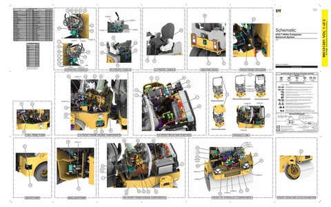
Component Location - Volume 1
Port - 12V Pow er Receptacle - Bussed C1 Receptacle - Bussed C2 Relay - Engine ECM Relay - Glow Plug Relay - Main Relay - Solid State Flasher Relay - Starter Resistor - Terminating 1 CAN 0 Resistor - Terminating 1 CAN C Resistor - Terminating CAN 0 Resistor - Terminating CAN C Sender - Fuel Sender - Water Level Sensor - Air Inlet Temperature Sensor - CMV Accelerometer Sensor - Hydraulic Temperature Sensor - Water In Fuel Solenoid - Fan Solenoid - Front Vibe Solenoid - Park Brake Solenoid - Seat Sw itch Hydraulic Lockout Sw itch - Air Filter Restriction Sw itch - Battery Disconnect Sw itch - Beacon Sw itch - Emulsion Spray (CC Models Only) Sw itch - Engine Speed Sw itch - E-Stop Sw itch - Hazard Sw itch - Horn Sw itch - Key Start Sw itch - Neutral Sw itch - Parking Brake Sw itch - Rear Work Lights Sw itch - Road Position Lights Sw itch - Seat Left Sw itch - Seat Right Sw itch - Turn Signal Sw itch - Water Spray Sw itch - Work Lights Tee - 12V Pow er Splice
Schem atic Location I-15 G-15 E-15 H-4 G-4 H-4 C-14 F-4 F-16 G-8 E-4 E-11 D-6 H-16 G-8 D-4 F-4 D-11 F-4 D-6 D-11 D-11 G-8 F-2 E-12 D-12 E-12 E-12 G-12 H-12 C-12 D-11 D-12 H-12 G-12 H-15 H-15 G-12 H-12 H-12 F-1
Machine Location 42 43 44 45 46 47 48 49 50 51 52 53 54 55 56 57 58 59 60 61 62 63 64 65 66 67 68 69 70 71 72 73 74 75 76 77 78 79 80 81 82
8
66
68
67
M0131251 July 2021
74
72 69
Connector Num ber
CONN 2A
D-4 , J-14
CONN 2B
D-4 , J-14
CONN 3
J-14
CONN 4
I-14
CONN 5 DIAGNOSTIC PORT
I-15
CONN 6
H-14
CONN 7
D-13
CONN 8
D-13
CONN 9
E-13
CONN 10
E-13
CONN 11
E-13
CONN 12
G-12
CONN 13
A-12
CONN 14
H-8
CONN 15
E-8
CONN 16
E-8
CONN 17
F-8
CONN 18
D-6
CONN 19
C-6
CONN 20
D-4
CONN 21
D-4
CONN 22
E-3 , E-4
CONN 23
E-3 , E-4
CONN 24
E-3
CONN 25
D-3
CONN 26
D-3
The connectors show n in this chart are for harness to harness connectors. Connectors that join a harness to a component are generally located at or near the component. See the Component Location Chart.
CONN 4
CONN 3
44
36
CC2.7 Utility Compactor Electrical System
37
6421-UP 6451-UP
CONN 10
CONN 9
CONN 7
Connector Location - Volume 1
CONN 1
29
CONN 5
1 Schem atic Location J-14
48
CONN 6
50
42 43
10
80
70
71
55
79
81
78
76
77 2
75 CONN 11
31
32
30
Volume 1 of 2: Machine
33 CONN 8
PUBLICATIONS.CAT.COM
CONN 12
OPERATOR CONSOLE
LH PROPEL HANDLE
RH PROPEL HANDLE
MACHINE REAR
REAR FRAME GROUNDS Harness And Wire Electrical Schematic Symbols
13 51
CONN 14
22
21
20
28 6
Symbols
45
7
T
Pressure Symbol
47
Temperature Symbol
Level Symbol
Flow Symbol
Circuit Breaker Symbol
Symbols and Definitions Fuse: A component in an electrical circuit that will open the circuit if too much current flows through it.
CONN 1
46
Switch (Normally Open): A switch that will close at a specified point (temp, press, etc.). The circle indicates that the component has screw terminals and a wire can be disconnected from it.
CONN 2A CONN 2B
15
Switch (Normally Closed): A switch that will open at a specified point (temp, press, etc.). No circle indicates that the wire cannot be disconnected from the component. Ground (Wired): This indicates that the component is connected to a grounded wire. The grounded wire is fastened to the machine.
12
17
Ground (Case): This indicates that the component does not have a wire connected to ground. It is grounded by being fastened to the machine. Reed Switch: A switch whose contacts are controlled by a magnet. A magnet closes the contacts of a normally open reed switch; it opens the contacts of a normally closed reed switch.
5 VIEW OF PLE243 / PLE643 ROPS VIEW OF PLE683 ROPS
CONN 18 18
VIEW OF PLE643 CANOPY
Sender: A component that is used with a temperature or pressure gauge. The sender measures the temperature or pressure. Its resistance changes to give an indication to the gauge of the temperature or pressure.
T
CONN 25
54
Relay (Magnetic Switch): A relay is an electrical component that is activated by electricity. It has a coil that makes an electromagnet when current flows through it. The electromagnet can open or close the switch part of the relay.
CONN 20
60
Solenoid: A solenoid is an electrical component that is activated by electricity. It has a coil that makes an electromagnet when current flows through it. The electromagnet can open or close a valve or move a piece of metal that can do work.
16
Magnetic Latch Solenoid: A magnetic latch solenoid is an electrical component that is activated by electricity and held latched by a permanent magnet. It has two coils (latch and unlatch) that make electromagnet when current flows through them. It also has an internal switch that places the latch coil circuit open at the time the coil latches.
Harness and Wire Symbols
59
11
BELOW FUEL PUMP
Wire, Cable, or Harness Assembly Identification: Includes Harness Identification Letters and Harness Connector Serialization Codes (see sample).
Harness Identification Letter(s): (A, B, C, ..., AA, AB, AC, ...)
L-C12 3E-5179
AG-C4 111-7898
L-C12 3E-5179
1
Part Number: for Connector Plug
Harness Connector Serialization Code: The "C" stands for "Connector" and the number indicates which connector in the harness (C1, C2, C3, ...).
Part Number: for Connector Receptacle
2 5A Plug
VIEW OF PLE683 CANOPY
39
9
FUEL PRIME PUMP
53
1 2
Deutsch connector: Typical representation of a Deutsch connector. The plug contains all sockets and the receptacle contains all pins.
1 2
Sure-Seal connector: Typical representation of a Sure-Seal connector. The plug and receptacle contain both pins and sockets.
Fuse (5 Amps)
9X-1123
Component Part Number
325-AG135 PK-14 Harness identification code: This example indicates wire group 325, wire 135 in harness "AG".
Wire Gauge* Wire Color
*Wire gauge is shown in AWG (American Wire Gauge) but could also be shown in metric denoted with mm
© 2021 Caterpillar. All Rights Reserved. CAT, CATERPILLAR, LET’S DO THE WORK, their respective logos, “Caterpillar Corporate Yellow”, the “Power Edge” and Cat “Modern Hex” trade dress as well as corporate and product identity used herein, are trademarks of Caterpillar and may not be used without permission.
LH FRONT FRAME ENGINE COMPONENTS 38
CONN 26
26
Receptacle Pin or Socket Number
LH FRONT RELAY AND FUSE BOX 64
56
PRODUCT LINK
82
CONN 13
41
CONN 15 CONN 17 CONN 16
63
57
73 49 61 BELOW VALVE
35
4 62
34 CONN POINT FOR INLET HEATER IF EQUIPPED
CONN 24 CONN 23
3
CONN 22
19 14 25
65
23
40
24
BEHIND PLATE
WATER PUMP
EMULSION PUMP
RH FRONT FRAME ENGINE COMPONENTS
52
CONN 21 CONN 19
27
58
FRONT OF HYDRAULIC COMPARTMENT
FRONT DRUM CMV ACCELEROMETER
(Dimensions: 56 inches x 35 inches)
Com ponent
42 Page,
Machine Location 1 2 3 4 5 6 7 8 9 10 11 12 13 14 15 16 17 18 19 20 21 22 23 24 25 26 27 28 29 30 31 32 33 34 35 36 37 38 39 40 41
M0131251 VOL 1 of 2
Schem atic Location Alarm - Action F-12 Alarm - Backup B-14 Alternator F-2 Battery - 12Volt E-1 Block - Main Fuse F-2 Block As - Relay / Fuse / Breaker (Sw itched Pow er) H-6 Block As - Relay / Fuse / Breaker (Un-Sw itched Pow er) H-5 Control - Display F-12 Control - Engine H-11 Control - Machine F-16 Control - Netw ork Manager D-2 Control - PL083 SAT/CELL Option J-16 Control - PL243 CELL Option J-15 Diode - Emulsion Pump (CC Models Only) A-13 Diode - Engine ECM F-4 Diode - Glow Plugs F-6 Diode - Machine ECM F-4 Diode - Prime Lift Pump D-11 Diode - Water Pump A-13 Glow Plug #1 F-8 Glow Plug #2 F-8 Glow Plug #3 F-8 Ground - Engine F-3 Ground - Frame F-3 Ground - Frame (Battery Disconnect) E-2 Ground - Front Frame 1 E-9 Ground - Front Frame 2 D-7 Ground - Front Frame 3 F-1 Ground - Platform G-14 Ground - Rear Frame 1 G-15 Ground - Rear Frame 2 A-11 Ground - Rear Frame 3 F-2 Ground - Water Sender Case H-16 Heater - Breather F-8 Horn - Forw ard F-4 Lever - LH Propel Handle I-15 Lever - RH Propel Handle I-15 Motor - Emulsion Pump (CC Models Only) A-13 Motor - Prime Lift Pump D-11 Motor - Starter F-3 Motor - Water Pump A-13 Com ponent