M0124311 November 2020
13 Component Location - Volume 1
CONN 1 CONN 2 CONN 3 CONN 4 CONN 5 CONN 6 CONN 7 CONN 8 CONN 9 CONN 10 CONN 11 CONN 12 CONN 13 CONN 14 CONN 15 CONN 16 CONN 17 CONN 18 CONN 19 CONN 20 CONN 21 CONN 22 CONN 23 CONN 24 CONN 25 CONN 26
Schem atic Location J-13 , J-16 J-16 I-16 I-16 H-16 G-16 E-16 D-16 C-16 D-13 E-13 F-13 E-8 E-8 E-5 E-5 E-5 C-3 D-3 D-3 J-1 J-1 I-1 H-16 E-1 D-1 , D-2
CONN 10 CONN 16
CONN 11 26
CONN 12
CONN 17
14
46
51
8 49
48
56 60
4
7
18
52 24
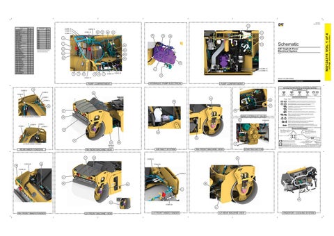
CB7 Asphalt Paver Electrical System
50
The connectors show n in this chart are for harness to harness connectors. Connectors that join a harness to a component are generally located at or near the component. See the Component Location Chart.
27
M5R1-UP
43
23
44 55
CONN 13 CONN 14
47 6
5
25
10
12
3
CONN 19 CONN 18 37
CONN 15
Volume 1 of 2: Main Chassis
HYDRAULIC PUMP ELECTRICAL
PUMP COMPARTMENT
PUMP COMPARTMENT Harness And Wire Electrical Schematic Symbols
15
CONN 8
Symbols
CONN 6
30
CONN 9
T
Pressure Symbol
Temperature Symbol
Level Symbol
Flow Symbol
Circuit Breaker Symbol
Symbols and Definitions
CONN 7
34
Fuse: A component in an electrical circuit that will open the circuit if too much current flows through it.
54
CONN 5
Switch (Normally Open): A switch that will close at a specified point (temp, press, etc.). The circle indicates that the component has screw terminals and a wire can be disconnected from it.
32
Switch (Normally Closed): A switch that will open at a specified point (temp, press, etc.). No circle indicates that the wire cannot be disconnected from the component.
57
28
Ground (Wired): This indicates that the component is connected to a grounded wire. The grounded wire is fastened to the machine. Ground (Case): This indicates that the component does not have a wire connected to ground. It is grounded by being fastened to the machine.
53
2
RH REAR INNER FENDER
Reed Switch: A switch whose contacts are controlled by a magnet. A magnet closes the contacts of a normally open reed switch; it opens the contacts of a normally closed reed switch.
22 CONN 4
CONN 3
T
MAIN HYDRAULIC VALVE
38
Sender: A component that is used with a temperature or pressure gauge. The sender measures the temperature or pressure. Its resistance changes to give an indication to the gauge of the temperature or pressure. Relay (Magnetic Switch): A relay is an electrical component that is activated by electricity. It has a coil that makes an electromagnet when current flows through it. The electromagnet can open or close the switch part of the relay.
CONN 20
Solenoid: A solenoid is an electrical component that is activated by electricity. It has a coil that makes an electromagnet when current flows through it. The electromagnet can open or close a valve or move a piece of metal that can do work.
CONN 1
Magnetic Latch Solenoid: A magnetic latch solenoid is an electrical component that is activated by electricity and held latched by a permanent magnet. It has two coils (latch and unlatch) that make electromagnet when current flows through them. It also has an internal switch that places the latch coil circuit open at the time the coil latches.
CONN 2
Harness and Wire Symbols
16
Wire, Cable, or Harness Assembly Identification: Includes Harness Identification Letters and Harness Connector Serialization Codes (see sample).
59
Harness Identification Letter(s): (A, B, C, ..., AA, AB, AC, ...)
L-C12 3E-5179
AG-C4 111-7898
1
Part Number: for Connector Plug
5A Plug
41 LH REAR INNER FENDER
36
11
BEHIND PLATE
REAR INNER FENDERS
CONN 26
Receptacle Pin or Socket Number
1 2
Deutsch connector: Typical representation of a Deutsch connector. The plug contains all sockets and the receptacle contains all pins.
1 2
Sure-Seal connector: Typical representation of a Sure-Seal connector. The plug and receptacle contain both pins and sockets.
Fuse (5 Amps)
9X-1123
AIR INLET SYSTEM
29
325-AG135 PK-14 Harness identification code: This example indicates wire group 325, wire 135 in harness "AG".
58
33
CONN 22
19 CONN 25 CONN 21 1
39
40
9
45 31 CONN 24 21
RH FRONT INNER FENDER
LH FRONT MACHINE VIEW
Wire Gauge* Wire Color
*Wire gauge is shown in AWG (American Wire Gauge) but could also be shown in metric denoted with mm
STARTING MOTOR
RH FRONT MACHINE VIEW
CONN 23
35
Component Part Number
© 2019 Caterpillar. All Rights Reserved. CAT, CATERPILLAR, LET’S DO THE WORK, their respective logos, “Caterpillar Yellow,” the “Power Edge” and Cat “Modern Hex” trade dress, as well as corporate and product identity used herein, are trademarks of Caterpillar and may not be used without permission.
RH REAR MACHINE VIEW
17
Part Number: for Connector Receptacle
2
42 20
L-C12 3E-5179
Harness Connector Serialization Code: The "C" stands for "Connector" and the number indicates which connector in the harness (C1, C2, C3, ...).
LH FRONT INNER FENDER
LH REAR MACHINE VIEW
RADIATOR / COOLING SYSTEM
(Dimensions: 56 inches x 35 inches)
Connector Num ber
42 Page,
ALARM - BACKUP 360 FONT ALARM - BACKUP REAR BATTERY - 12V BLOCK AS - MINI FUSES (SW- POWER) BLOCK AS - RELAYS BLOCK AS - RELAYS / M FUSES (UNSW- POWER) FUSE - MAIN MODULE GROUND - FRAME GROUND - FRONT BUMPER GROUND - LEFT BACK WALL GROUND - LEFT FRAME GROUND - LEFT SIDE FRAME GROUND - PLATFORM GROUND - RIGHT FLOOR GROUND - RR BUMPER HORN - 360 ROTATE REAR HORN - FRONT LAMP - DEF PURGE MODULE - MAT TEMPERATURE SENSOR INPUT MOTOR - FRONT WATER MOTOR - REAR WATER MOTOR - STARTER RELAY - ENGINE CONTROL MODULE RELAY - GLOW PLUG RELAY - MACHINE MAIN RELAY - SCR RELAY - STARTER RESISTOR - TERMINATING CAN B SENDER - FUEL LEVEL SENDER - WATER LEVEL SENSOR - ACCELEROMETER SENSOR - AIR INLET TEMPERATURE SENSOR - DRUM SPEED LR (CB7) SENSOR - DRUM SPEED RF (CB7) SENSOR - FRONT MAT TEMPERATURE SENSOR - FRONT STEER SENSOR - HYDRAULIC OIL TEMPERATURE SENSOR - REAR MAT TEMPERATURE SENSOR - STEERING ANGLE SENSOR - VIBE SPEED LF SENSOR - VIBE SPEED RR SENSOR - WATER IN FUEL SOLENOID - FRONT CCW VALVE SOLENOID - FRONT CW VALVE SOLENOID - HYDRAULIC FAN SOLENOID - HYDRAULIC WARM UP SOLENOID - PARKING BRAKE SOLENOID - PROPEL PUMP FORWARD SOLENOID - PROPEL PUMP REVERSE SOLENOID - REAR CCW VALVE SOLENOID - REAR CW VALVE SOLENOID - STEER SHUNT VALVE SOLENOID - TWO SPEED SOLENOID - VIBE FRONT DRUM SOLENOID - VIBE MA SOLENOID - VIBE MB SOLENOID - VIBE REAR DRUM SOLENOID - WATER SPRAY FRONT SWITCH - AIR INLET RESTRICTION SWITCH - MAIN DISCONNECT
Connector Location - Volume 1
Schem atic Machine Location Location E-1 1 H-16 2 C-4 3 I-5 4 I-5 5 H-5 6 D-5 7 C-4 8 I-1 9 C-3 10 C-5 11 I-8 12 C-4 13 B-8 14 F-16 15 H-16 16 H-1 17 I-8 18 E-1 19 F-6 20 F-6 21 D-5 22 C-5 23 D-5 24 D-6 25 G-6 26 D-5 27 H-16 28 J-8 29 E-16 30 I-1 31 J-8 32 J-14 33 D-1 34 G-1 35 D-13 36 D-8 37 F-16 38 D-13 39 J-1 40 D-16 41 E-3 42 C-8 43 D-8 44 I-8 45 D-8 46 B-11 47 C-11 48 C-11 49 C-8 50 C-8 51 C-8 52 D-8 53 E-8 54 A-11 55 A-11 56 D-8 57 F-1 58 I-8 59 C-4 60
M0124311 VOL 1 of 4
Com ponent