M0118474-01 January 2021
CONN 28
17
16
CONN 43
1
91
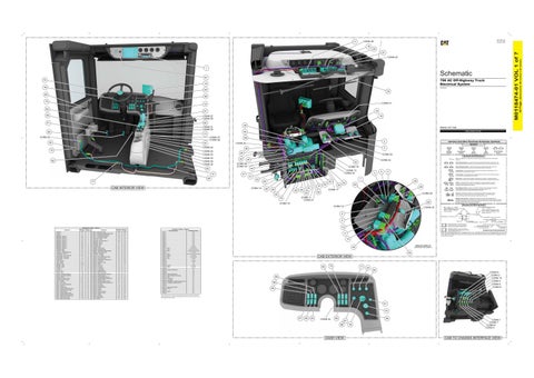
796 AC Off-Highway Truck Electrical System
70 14 76
HRZ508-524
54 85
32
58
73
CONN 41
15 83
19
27 59
CONN 27 CONN 39
18
82
61
29
CONN 31 CONN 30 60 CONN 22
CONN 37 CONN 38 57
2
CONN 20
CONN 25 CONN 23 CONN 33 CONN 36 CONN 35
62
PUBLICATIONS.CAT.COM
28
CONN 40 72
T
Pressure Symbol
CONN 32 42
4
6
Ground (Wired): This indicates that the component is connected to a grounded wire. The grounded wire is fastened to the machine.
5
Ground (Case): This indicates that the component does not have a wire connected to ground. It is grounded by being fastened to the machine.
CONN 14
7
94 49
35
36
38
37
51
39
79
46
63
24
Reed Switch: A switch whose contacts are controlled by a magnet. A magnet closes the contacts of a normally open reed switch; it opens the contacts of a normally closed reed switch. Sender: A component that is used with a temperature or pressure gauge. The sender measures the temperature or pressure. Its resistance changes to give an indication to the gauge of the temperature or pressure.
T
48
Relay (Magnetic Switch): A relay is an electrical component that is activated by electricity. It has a coil that makes an electromagnet when current flows through it. The electromagnet can open or close the switch part of the relay.
CONN 17 93
53
45
52
23
Circuit Breaker Symbol
Switch (Normally Closed): A switch that will open at a specified point (temp, press, etc.). No circle indicates that the wire cannot be disconnected from the component.
41
77
Flow Symbol
Switch (Normally Open): A switch that will close at a specified point (temp, press, etc.). The circle indicates that the component has screw terminals and a wire can be disconnected from it.
CONN 13 CONN 18 43
Level Symbol
Fuse: A component in an electrical circuit that will open the circuit if too much current flows through it.
CONN 16
47
Temperature Symbol
Symbols and Definitions
CONN 24
20
CONN 26 CONN 19 44
31 80
3
22 33
Harness And Wire Electrical Schematic Symbols Symbols
56
84
CAB INTERIOR VIEW
Volume 1 of 7: Cab
55
13
30
A
CONN 29
CONN 11 CONN 21
Solenoid: A solenoid is an electrical component that is activated by electricity. It has a coil that makes an electromagnet when current flows through it. The electromagnet can open or close a valve or move a piece of metal that can do work. Magnetic Latch Solenoid: A magnetic latch solenoid is an electrical component that is activated by electricity and held latched by a permanent magnet. It has two coils (latch and unlatch) that make electromagnet when current flows through them. It also has an internal switch that places the latch coil circuit open at the time the coil latches.
92
CONN 15
Harness and Wire Symbols
CONN 12
CONN 42
Wire, Cable, or Harness Assembly Identification: Includes Harness Identification Letters and Harness Connector Serialization Codes (see sample).
Harness Identification Letter(s): (A, B, C, ..., AA, AB, AC, ...)
L-C12 3E-5179
AG-C4 111-7898
8
L-C12 3E-5179
1
Part Number: for Connector Plug
Harness Connector Serialization Code: The "C" stands for "Connector" and the number indicates which connector in the harness (C1, C2, C3, ...).
Part Number: for Connector Receptacle
2 5A
9 10
Component Location - Volume 1 Component ADVISOR ALARM - 1 ALARM - 2 BREAKER - CIRCUIT 1 BREAKER - CIRCUIT 2 BREAKER - CIRCUIT 3 BREAKER - CIRCUIT 4 BREAKER - CIRCUIT 5 BREAKER - CIRCUIT 6 BREAKER - CIRCUIT 7 BREAKER - CIRCUIT 8 BREAKER - CIRCUIT 9 CONSOLE PANEL CONTROL - CMPD CONTROL - TRANSMISSION GP CONVERTER - 24V-12V CONVERTER - 24V-12V (CIODS) DIODE PANEL - HIGH SIDE DIODE PANEL - LOW SIDE FLASHER AS FUSE - HOLDER FUSE - INLINE GROUND - CAB 1 GROUND - CAB 2 GROUND - CAB 3 LIGHTER - 1 LIGHTER - 2 MOTOR - FAN 1 MOTOR - FAN 2 MOTOR - LH DRIVER WINDOW MOTOR - RH DRIVER WINDOW MOTOR - WIPER PASSTHRU - FUSED POWER POTENTIONMETER (HVAC) RELAY - ALARM RELAY - AUTOLUBE RELAY - AUTOLUBE PRESSURE RELAY - BACK UP RELAY - BRAKE LIGHT RELAY - CHECK ENGINE INDICATOR RELAY - GREEN PAYLOAD LAMP RELAY - MAIN POWER RELAY - PARKING BRAKE LAMP RELAY - PARKING BRAKE RELEASE RELAY - REAR AXLE COOLING FAN RELAY - REAR CIODS LAMP RELAY - RED PAYLOAD LAMP
Schematic Location G-1 I-7 I-7 B-4 B-4 B-4 B-4 B-4 B-4 B-4 B-4 B-4 G-7 C-11 G-8 D-1 B-13 I-7 H-7 F-4 E-1 B-13 E-14 H-14 G-1 E-7 E-7 D-4 D-4 I-13 I-12 H-1 F-16 F-8 E-5 G-5 D-6 F-5 D-5 I-12 F-5 E-4 E-6 D-6 C-6 C-13 F-5
Machine Location 1 2 3 4 5 6 7 8 9 10 11 12 13 14 15 16 17 18 19 20 21 22 23 24 25 26 27 28 29 30 31 32 33 34 35 36 37 38 39 40 41 42 43 44 45 46 47
Plug
Component RELAY - SIDE CIODS LAMP RELAY - STEERING ACCUMULATOR LAMP RELAY - STOP ENGINE INDICATOR RELAY - SYSTEM FAULT AMBER RELAY - SYSTEM FAULT RED RESISTOR - ALARM RESISTOR - CAN DATA LINK C 1 RESISTOR - FAN 1B RESISTOR - FAN 2B RESISTOR - GPS RH DASH PANEL SENSOR - HOIST LEVEL SENSOR - RETARD PEDAL SENSOR - SECONDARY BRAKE PEDAL SENSOR - THROTTLE PEDAL STANDOFF - CERAMIC SWITCH - A/C THERMO SWITCH - AUTO LUBE ALARM RESET SWITCH - AUTO LUBE TEST SWITCH - ENGINE SHUTDOWN DELAY SWITCH - FOG LIGHT SWITCH - HEAD/TAIL LIGHT SWITCH - HORN SWITCH - HVAC FAN SWITCH - LH DOOR SWITCH - LH WINDOW SWITCH - LOAD BRAKE SWITCH - MIRROR HEATER SWITCH - MULTI FUNCTION SWITCH - OPERATOR SEAT MAGNETIC SWITCH - PARKING BRAKE SWITCH - PARKING BRAKE RELAY SWITCH - PASSENGER SEAT MAGNETIC SWITCH - PRESS TO TEST SWITCH - RETARD SPEED CONTROL SWITCH - RETARD SPEED CONTROL SET SWITCH - RH DOOR SWITCH - RH WINDOW SWITCH - STAIRWAY LIGHT SWITCH - START 1 SWITCH - START 2 SWITCH - THROTTLE LOCK SWITCH - WINDOW LIGHT SWITCH - WIPER TIMER - AUTOLUBE TIMER - BRAKE DRAG VALVE - WATER
Schematic Location C-13 F-6 I-12 E-6 D-5 E-5 B-13 E-4 E-4 C-7 G-7 H-11 D-7 B-7 D-7 G-1 F-7 G-4 G-4 I-12 G-4 F-4 D-7 H-7 I-15 I-15 E-7 H-9 D-7 G-6 F-7 C-6 G-6 E-7 G-7 F-7 I-15 I-15 F-4 G-11 G-11 I-12 H-9 G-1 D-4 E-5 F-7
Machine Location 48 49 50 51 52 53 54 55 56 57 58 59 60 61 62 63 64 65 66 67 68 69 70 71 72 73 74 75 76 77 78 79 80 81 82 83 84 85 86 87 88 89 90 91 92 93 94
Connector Location - Volume 1 Connector Number CONN 1 CONN 2 CONN 3 CONN 4 CONN 5 CONN 6 CONN 7 CONN 8 CONN 9 CONN 10 CONN 11 CONN 12 - TB15 CONN 13 - TB12 CONN 14 - TB10 CONN 15 CONN 16 - TB13 CONN 17 - GND15 CONN 18 - TB11 CONN 19 - TB16 CONN 20 CONN 21 CONN 22 CONN 23 CONN 24 - GND16 CONN 25 - TB18 CONN 26 CONN 27 - ENGINE DIAGNOSTIC CONN 28 CONN 29 CONN 30 - FIRE SUPPRESSION CONN 31 - USER DEFINED SHUTDOWN CONN 32 - TB14 CONN 33 - TO MP-GPS CONN 34 - TO TC-900 CONN 35 - ETHERNET TO MINESTAR RADIO (ATH) CONN 36 - TO MINESTAR RADIO (ATCH) CONN 37 CONN 38 CONN 39 - VIMS SERVICE PORT CONN 40 - RTN18 CONN 41 CONN 42 - GND17 CONN 43
Schematic Location I-16 H-16 G-16 F-16 F-16 E-16 D-16 D-16 C-16 B-16 G-15,E-9 H-15,H-12,C-4 H-15,G-14,D-14,F-9 H-15,H-14,E-14,D-14,D-9 F-14,E-9 F-14,E-14,D-14,H-13,B-7,C-5 F-14,B-7 D-14,H-13,G-9 C-14,B-5 C-13 G-13,E-9 I-13 I-13 G-12,E-4 G-12,H-5 H-11 I-11 B-9 C-9 C-9 C-9 J-9 B-7 C-7 C-7 C-7 G-7 G-7 G-7 G-5 G-4 D-4 D-1
11
Receptacle Pin or Socket Number
1 2
Deutsch connector: Typical representation of a Deutsch connector. The plug contains all sockets and the receptacle contains all pins.
1 2
Sure-Seal connector: Typical representation of a Sure-Seal connector. The plug and receptacle contain both pins and sockets.
9X-1123
Fuse (5 Amps)
Component Part Number
325-AG135 PK-14 Harness identification code: This example indicates wire group 325, wire 135 in harness "AG".
Wire Gauge* Wire Color
*Wire gauge is shown in AWG (American Wire Gauge) but could also be shown in metric denoted with mm
© 2021 Caterpillar. All Rights Reserved. CAT, CATERPILLAR, LET’S DO THE WORK, their respective logos, “Caterpillar Corporate Yellow”, the “Power Edge” and Cat “Modern Hex” trade dress as well as corporate and product identity used herein, are trademarks of Caterpillar and may not be used without permission.
12 VIEW OF AREA “A”
40
(ROTATED FOR CLARITY)
50
CAB EXTERIOR VIEW 90
75
71
34 64 CONN 6 CONN 3 CONN 10 CONN 9 CONN 8 CONN 5
89 86 69
The connectors shown in this chart are for harness to harness connectors. Connectors that join a harness to a component are generally located at or near the component. See the Component Location Chart.
81 74 67
66
65
CONN 34
68
26 87 88
DASH VIEW
78
CONN 1 CONN 7 CONN 4 CONN 2
CAB TO CHASSIS INTERFACE VIEW
(Dimensions: 56 inches x 35 inches)
21
42 Page,
M0118474-01 VOL 1 of 7
25