48
H-16
Breaker - Brake Retract Mtr
G-4
2
CONN 3
F-16
Breaker - Condenser Fan 1
G-4
3
61
CONN 4
D-16
Breaker - Condenser Fan 2
G-4
4
G-4
5
47
J-14
CONN 6
I-14
Breaker - Headlamps
G-4
6
CONN 7
G-14
Control - Cab Air Temp Dial
G-1
7
CONN 8
D-14
Display - Digital Payload (Master)
I-12
8
CONN 9
I-13
Display - Indicator
D-5
9
CONN 10
I-12
Fuse Block 1
I-5
10
CONN 11
I-12
Fuse Block 2
H-5
11
CONN 12
I-12
Fuse Block 3 12V
G-5
12
CONN 13
H-12, I-12
Ground - Cab 1
J-3
13
Ground - Cab 2
I-3
14
Ground - Cab 3
I-3
15
Ground - Cab 4
I-3
16
Ground - Cab 5
I-3
17
Ground - Cab 6
I-3
18
Lever - Retarder
F-1
19
Lever - Transmission
C-12
20
Motor - LH Window (Atch)
E-4
21
Motor - RH Window (Atch)
H-12
22
Pass Through - Cab
F-4
23
Port - 12V Power 1 (Atch)
B-5
24
Port - 12V Power 2 (Atch)
D-5
25
CONN 14
44 CONN 17 53 52 49
9
19
25
CONN 19 42
43
46
41
40 CONN 16 62
CONN 35
CONN 18
20
CONN 36
34
56
CONN 12 CONN 38 CONN 22 CONN 21
59 28
Alarm - Action
Breaker - Condenser Fan 3
CONN 5
63
Component
Machine Location 1
H-12
CONN 15
H-12
CONN 16
D-12
CONN 17
D-12
CONN 18
C-12
CONN 19
D-11
CONN 20
E-11
CONN 21
F-11
CONN 22
F-11
CONN 23
J-11
CONN 24
J-11
CONN 25
F-7
Port - Rear Power
F-5
26
CONN 26
F-7
Relay - Main Power
G-4
27
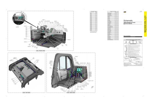
789G Off-Highway Truck Electrical System
CONN 27
F-7
Resistor - LH Turn
B-5
28
CONN 28
F-7
TR21-UP
Resistor - RH Turn
B-5
29
CONN 29
G-6
Resistor - Term. A
E-2
30
CONN 30
G-7
Resistor - VIMS Local Can 2
E-6
31
CONN 31
G-7
Sensor - 3 Channel BK Pedal Position
E-1
32
CONN 32
G-7
Sensor - 4 Channel BK Pedal Position
E-1
33
CONN 33
E-6
Sensor - Hoist Position
C-12
34
CONN 34
E-6
Sensor - Secondary Brake Pedal Posn
E-1
35
CONN 35
E-4
Sensor - Throttle
E-1
36
CONN 36
H-2
Suppressor - Hazard 1
D-5
37
CONN 37
F-2
Suppressor - Hazard 2
D-5
38
CONN 38
D-2
Switch - A/C On/Off
G-1
39
CONN 39
H-1
Switch - Arc. Inc/Dec
E-11
40
CONN 40
I-1
Switch - Arc. Inc/Dec (Atch)
E-12
41
CONN 41
I-1
Switch - Arc. Mode (Atch)
E-12
42
Switch - Arc. On/Off
E-11
43
Switch - Backlight Dimmer
D-1
44
Switch - Brake Retract
G-1
45
Switch - Column
F-1
46
Switch - Curb Vision Lamps
D-1
47
Switch - Fog Light
C-1
48
Switch - Hazard
C-1
49
Switch - Head Lamps
D-1
50
Switch - Heated Mirror (Atch)
G-1
51
Switch - Horn
E-1
52
Switch - Key
The connectors shown in this chart are for harness to harness connectors. Connectors that join a harness to a component are generally located at or near the component. See the Component Location Chart.
29 35 21
CONN 33 CONN 20
D-12
53
Switch - LH Door
F-5
54
Switch - LH Map Lamp
H-1
55
Switch - LH Window
F-4
56
Switch - RH Door
F-5
57
Switch - RH Map Lamp
H-1
58
Switch - RH Window
E-4
59
Switch - Seat Belt
I-11
60
Switch - Stairway Lamp
C-1
61
Switch - Throttle Lock/Throttle Backup
C-12
62
Switch - Work Lamps/Rear Side Lamps
D-1
63
Volume 1 of 6: Cab (Interior) PUBLICATIONS.CAT.COM
Harness And Wire Electrical Schematic Symbols Symbols
CONN 34
T
Pressure Symbol
Temperature Symbol
Level Symbol
Flow Symbol
Circuit Breaker Symbol
Symbols and Definitions
54
24
36 CONN 24
Fuse: A component in an electrical circuit that will open the circuit if too much current flows through it. Switch (Normally Open): A switch that will close at a specified point (temp, press, etc.). The circle indicates that the component has screw terminals and a wire can be disconnected from it.
60
Switch (Normally Closed): A switch that will open at a specified point (temp, press, etc.). No circle indicates that the wire cannot be disconnected from the component.
33 32
Ground (Wired): This indicates that the component is connected to a grounded wire. The grounded wire is fastened to the machine.
1
Ground (Case): This indicates that the component does not have a wire connected to ground. It is grounded by being fastened to the machine. Reed Switch: A switch whose contacts are controlled by a magnet. A magnet closes the contacts of a normally open reed switch; it opens the contacts of a normally closed reed switch.
CAB - FRONT VIEW
Sender: A component that is used with a temperature or pressure gauge. The sender measures the temperature or pressure. Its resistance changes to give an indication to the gauge of the temperature or pressure.
T
Relay (Magnetic Switch): A relay is an electrical component that is activated by electricity. It has a coil that makes an electromagnet when current flows through it. The electromagnet can open or close the switch part of the relay. Solenoid: A solenoid is an electrical component that is activated by electricity. It has a coil that makes an electromagnet when current flows through it. The electromagnet can open or close a valve or move a piece of metal that can do work. Magnetic Latch Solenoid: A magnetic latch solenoid is an electrical component that is activated by electricity and held latched by a permanent magnet. It has two coils (latch and unlatch) that make electromagnet when current flows through them. It also has an internal switch that places the latch coil circuit open at the time the coil latches.
CONN 37
Harness and Wire Symbols
CONN 40 CONN 41
58
CONN 11 CONN 10
Wire, Cable, or Harness Assembly Identification: Includes Harness Identification Letters and Harness Connector Serialization Codes (see sample).
30 CONN 39
23
L-C12 3E-5179
1
Part Number: for Connector Plug
Harness Connector Serialization Code: The "C" stands for "Connector" and the number indicates which connector in the harness (C1, C2, C3, ...).
Part Number: for Connector Receptacle
2 5A
CONN 8 CONN 7 10 CONN 6 CONN 5
CONN 9 CONN 1
Plug
11
12
26
22
2 3
57 5 6 CONN 25 CONN 26 CONN 28 CONN 27 CONN 31 CONN 29 CONN 32 31 51 8
39
NOT SHOWN
7 17
45 15 13 37 CONN 3
CONN 30
CONN 4 CONN 23
CONN 13 CONN 15
27
CAB - REAR VIEW
38
CONN 14
14
Receptacle Pin or Socket Number
1 2
Deutsch connector: Typical representation of a Deutsch connector. The plug contains all sockets and the receptacle contains all pins.
1 2
Sure-Seal connector: Typical representation of a Sure-Seal connector. The plug and receptacle contain both pins and sockets.
Fuse (5 Amps)
9X-1123
Component Part Number
325-AG135 PK-14 Harness identification code: This example indicates wire group 325, wire 135 in harness "AG".
Wire Gauge* Wire Color
*Wire gauge is shown in AWG (American Wire Gauge) but could also be shown in metric denoted with mm
© 2021 Caterpillar. All Rights Reserved. CAT, CATERPILLAR, LET’S DO THE WORK, their respective logos, “Caterpillar Corporate Yellow”, the “Power Edge” and Cat “Modern Hex” trade dress as well as corporate and product identity used herein, are trademarks of Caterpillar and may not be used without permission.
4
CAB - TOP VIEW
L-C12 3E-5179
AG-C4 111-7898
CONN 2 55
Harness Identification Letter(s): (A, B, C, ..., AA, AB, AC, ...)
18
16 FW
D
(Dimensions: 56 inches x 35 inches)
CONN 2
Connector Number
Schematic Location C-5
42 Page,
CONN 1
Schematic Location I-16
M0114030 VOL 1 of 6
50
M0114030 January 2021
Component Location - Volume 1
Connector Location - Volume 1