Component
Connector Location - Volume 1 Schematic Location
Connector Number
52 53
57 68 1
Schematic Location
Machine Location 30
Alarm - Action (VIMS)
D-5
1
Relay - Window (Down)
J-14
Alarm - Seat Belt
D-5
2
Relay - Window (Up)
J-14
31
Block - Fuse
I-12
3
Relay - Wiper (High)
I-14
32
Relay - Headlamp
J-12
3
Resistor - J1939 Terminating
A-8
34
Relay - Prelube
J-12
3
Resistor - Turn Lamp (LH)
I-2
35
Relay - Engine Idle Shutdown
J-12
3
Resistor - Turn Lamp (RH)
I-2
36
B-16
Relay - Stop Lamp
J-12
3
Sensor - Hoist Lever Position
A-5
37
CONN 2
C-16
Relay - Differential Fan
J-12
3
Sensor - Pressure (Brake Air)
H-16
38
CONN 3
D-16
Relay - Wiper Intermittent
J-12
3
Sensor - Throttle Position
I-2
39
CONN 4
E-16
Relay - Fog Lamp
I-12
3
Solenoid - Auto Lube
B-11
40
CONN 5
J-16
Relay - Backup
I-12
3
Solenoid - Brake Cooling Diverter (Front)
H-16
41
CONN 6
J-16
Relay - CIODS Lamps (Side)
I-12
3
Solenoid - Horn
CONN 7
A-11
I-12
3
CONN 8
E-11
Relay - CIODS Lamps (Rear) Blower As
J-1
18
F-8
42
Solenoid - Machine Lockout
B-11
43
Switch - (ARC) Automatic Retarder Control
D-1
44
A-7
Breaker - A/C
H-12
4
Switch - (TCS) Traction Control System Test
C-1
45
CONN 10
CAT ET Service Port
A-8
Breaker - Alternator
H-12
5
Switch - A/C (On)
D-2
46
CONN 11
Cab Serial Download Port
B-8
Breaker - Brake Retract
H-12
6
Switch - Blower
E-2
47
CONN 12
B-7
Control Module - Steering Bleed
I-16
7
Switch - Brake Retract
D-1
48
CONN 13
B-7
Converter - 20A Power
J-14
8
Switch - Dome Lamp
C-7
49
CONN 14
C-7
Diode - Horn Solenoid
F-8
9
Switch - Engine Idle Speed
D-2
50
CONN 15
A-3
Display - Digital Payload (LH)
E-13
10
Switch - Fog Lamp
C-5
51
CONN 16
A-3
ECM - (RAC) Road Analysis Control
G-13
11
Switch - Hazard Lamp
B-5
52
CONN 17
B-3
C-13
12
Switch - Headlamp
B-5
53
CONN 18
E-4
ECM - Brake ECM - (VIMS) Vital Info Management System
E-8
13
Switch - Heated Mirror Switch
D-2
54
CONN 19
F-4
ECM - XMSN
C-10
14
Switch - Horn
H-2
55
CONN 20
J-5
Ground - Rear Cab
I-8
15
Switch - Keystart
E-2
56
CONN 21
J-5
Module - Flasher
I-16
16
Switch - Ladder Lamp
C-5
57
CONN 22
J-2
Module - Wiper Delay
I-2
17
Switch - Lockout Brake Pressure
B-11
58
CONN 70
G-15
Motor - Power Window (Up & Down)
J-3
19
Switch - Panel Dimmer
E-2
59
J-2
20
Switch - Parking Brake
E-12
60
F-13
Motor - Washer
CONN 72 Minestar, XIM, TC900 Connector
F-11
Motor - Wiper
CONN 73
F-14
Outlet - 12V
CONN 71 Telemetry Download Port
2
Component
CONN 1
CONN 9
51
Machine Location
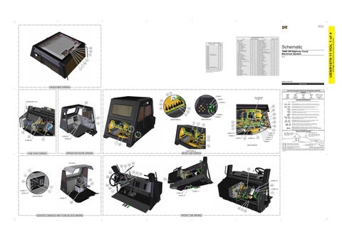
The connectors shown in this chart are for harness to harness connectors. Connectors that join a harness to a component are generally located at or near the component. See the Component Location Chart.
H-2
21
Switch - Power Window
J-3
61
G-12
22
Switch - Retarder
J-2
62
Port - 12V Power Relay - Brake Retract
I-2
23
Switch - Seat Belt
H-16
63
I-14
24
Switch - Service Brake
E-12
64
Relay - Heated Mirror
J-14
25
Switch - Steering Column
H-2
65
Relay - High Beam
I-14
26
Switch - Thermostat
I-1
66
Relay - Main Power
H-12
27
Switch - Throttle Backup / Lock
E-1
67
Relay - (RAX) Rear Axle Lubrication
I-16
28
Switch - Work Lamp
C-5
68
Relay - Seat Belt
I-14
29
Switch - XMSN Lever Position
A-5
69
789D Off-Highway Truck Electrical System SPD1-UP SHH1-UP
Volume 1 of 4: Cab
HEADLINER WIRING Harness And Wire Electrical Schematic Symbols Symbols
10 30 CONN 7
NOT SHOWN
CONN 73
CONN 1
32
WASHER BOTTLE
T
Pressure Symbol
29
Switch (Normally Closed): A switch that will open at a specified point (temp, press, etc.). No circle indicates that the wire cannot be disconnected from the component.
24
Ground (Wired): This indicates that the component is connected to a grounded wire. The grounded wire is fastened to the machine.
38 26
Ground (Case): This indicates that the component does not have a wire connected to ground. It is grounded by being fastened to the machine.
58
CONN 2
31
CONN 3
61
8
C
12
T
Relay (Magnetic Switch): A relay is an electrical component that is activated by electricity. It has a coil that makes an electromagnet when current flows through it. The electromagnet can open or close the switch part of the relay. Solenoid: A solenoid is an electrical component that is activated by electricity. It has a coil that makes an electromagnet when current flows through it. The electromagnet can open or close a valve or move a piece of metal that can do work.
42
D
Sender: A component that is used with a temperature or pressure gauge. The sender measures the temperature or pressure. Its resistance changes to give an indication to the gauge of the temperature or pressure.
64
27 11
Reed Switch: A switch whose contacts are controlled by a magnet. A magnet closes the contacts of a normally open reed switch; it opens the contacts of a normally closed reed switch.
60
VIEW OF AREA “B”
VIEW OF AREA “A”
43
Magnetic Latch Solenoid: A magnetic latch solenoid is an electrical component that is activated by electricity and held latched by a permanent magnet. It has two coils (latch and unlatch) that make electromagnet when current flows through them. It also has an internal switch that places the latch coil circuit open at the time the coil latches.
9 41
B
18
CONN 22
CONN 70
CONN 21
66
14
CONN 20
21
CONN 9 CONN 8
34
CONN 72
15
13 7
28
CONN 12 CONN 6 CONN 14 CONN 13 CONN 5
VIEW OF AREA “D”
16
OPERATOR DOOR WIRING
REAR CAB WIRING
HEADLINER
44 59
67
54 62
4 48
23
45
46
6 55
E
20
63
CONN 19
22 37 50 3 CONN 11
65 56
5
CONN 18 CONN 17
47
17
CONN 16
CONN 10
CONN 15
VIEW OF AREA “E”
CONN 71 69
36
CENTER CONSOLE AND FUSE BLOCK WIRING
FRONT CAB WIRING
Harness and Wire Symbols Wire, Cable, or Harness Assembly Identification: Includes Harness Identification Letters and Harness Connector Serialization Codes (see sample).
Harness Identification Letter(s): (A, B, C, ..., AA, AB, AC, ...)
L-C12 3E-5179
AG-C4 111-7898
L-C12 3E-5179
1
Part Number: for Connector Plug
Harness Connector Serialization Code: The "C" stands for "Connector" and the number indicates which connector in the harness (C1, C2, C3, ...).
Part Number: for Connector Receptacle
2 5A Plug
Receptacle Pin or Socket Number
1 2
Deutsch connector: Typical representation of a Deutsch connector. The plug contains all sockets and the receptacle contains all pins.
1 2
Sure-Seal connector: Typical representation of a Sure-Seal connector. The plug and receptacle contain both pins and sockets.
Fuse (5 Amps)
9X-1123
Component Part Number
325-AG135 PK-14 Harness identification code: This example indicates wire group 325, wire 135 in harness "AG".
Wire Gauge* Wire Color
*Wire gauge is shown in AWG (American Wire Gauge) but could also be shown in metric denoted with mm
© 2020 Caterpillar. All Rights Reserved. CAT, CATERPILLAR, LET’S DO THE WORK, their respective logos, “Caterpillar Yellow,” the “Power Edge” and Cat “Modern Hex” trade dress, as well as corporate and product identity used herein, are trademarks of Caterpillar and may not be used without permission.
VIEW OF AREA “C”
CAB HVAC WIRING
Circuit Breaker Symbol
Switch (Normally Open): A switch that will close at a specified point (temp, press, etc.). The circle indicates that the component has screw terminals and a wire can be disconnected from it.
40
A
Flow Symbol
Fuse: A component in an electrical circuit that will open the circuit if too much current flows through it.
25
19
Level Symbol
Symbols and Definitions
CONN 4
49
Temperature Symbol
35
39
(Dimensions: 56 inches x 35 inches)
Component Location - Volume 1 Schematic Location
42 Page,
UENR1079-11 VOL 1 of 4
UENR1079-11 October 2020