28
13
17 37
2
CONN 19 CONN 20 CONN 17 CONN 13 CONN 15
11 49
39 14
33
1
36
CONN 32 CONN 33 CONN 34 CONN 9
19
12
46
20
CONN 23
18 21
16
LOCATED AT BOTTOM RH CORNER OF ECM
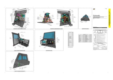
789D CMD Off-Highway Truck Electrical System
45
51
SPD1-UP AX71-UP
47
8
50
34 7
CONN 36
CONN 8
CONN 37
CONN 35
CONN 26 15
CONN 22 CONN 11 CONN 21
CONN 27 4 35
32
CONN 18
5
22
38 CONN 12 CONN 16
44
23
52 Volume 1 of 7: Cab
CONN 14 PUBLICATIONS.CAT.COM
CAB REAR COMPARTMENT LH VIEW
CAB REAR COMPARTMENT RH VIEW
CAB BOTTOM VIEW Harness And Wire Electrical Schematic Symbols Symbols
T
CONN 28
Connector Location - Volume 1
NOT SHOWN
CONN 1
Schematic Location I-16
CONN 2
H-16
CONN 3
F-16
Connector Number
56 54 57 55
27
3
CONN 39 CONN 38 24 NOT SHOWN
30 26
40
E-16
CONN 5
D-16
Component Location - Volume 1
Block - Fuse 1
Schematic Location I-4
Machine Location 1
Port - +12V Power
Schematic Location I-1
Block - Fuse 2
G-4
2
Port - +24V Power
Component
Component
A-16
A-16
31
CONN 8
I-15
Blower As
J-1
3
Relay - Brake Retract
I-14
32
CONN 9
J-15
Breaker - Air Conditioning
D-4
4
Relay - Heated Mirror
I-14
33
CONN 10 - Comm Radio
I-12
Breaker - Brake Retract
D-4
5
Relay - High Beam
I-14
34
Busbar - A
G-4
6
Relay - Key Switch
J-14
35
CONN 11 - Custom Third Party
F-11
Busbar - B
E-4
7
Relay - Key Switch Enable
J-14
36
CONN 12 - To Telematics Radio
F-11
Busbar - C
E-4
8
Relay - Main Power
E-4
37
CONN 13 - Minestar LP-GPS
F-11
Busbar - D
E-4
9
Relay - Window Down
J-14
38
Control - Brake
D-12
10
Relay - Window Up
I-14
39
CONN 14 - Minestar Power
F-11
Control - Chassis
D-6
11
Resistor - LH Turn
I-1
40
CONN 15 - Minestar MP-GPS
G-11
Control - Primary Steering
D-5
12
Resistor - RH Turn
H-1
41
CONN 16 - To Minestar TC-900
G-11
Control - Trasmission
D-10
13
Resistor - Terminating 1
G-16
42 43
CONN 17 - CAN A / CAN B Conn
H-11
CONN 18
B-8
CONN 19
H-6
CONN 20
G-6
Ground - Case Chassis
D-6
19
Sensor - Throttle Position
CONN 21
E-5
Ground - Case Steering
D-5
20
Solenoid - Autolube
CONN 22
E-5
Ground - Case Transmission
D-10
21
Solenoid - Front Brake Cooling Diverter
I-16
50
Ground - Rear Cab Boss
E-6
22
Solenoid - Horn
I-12
51
CONN 23
F-5
Ground - Rear Cab Boss 2
E-6
23
Solenoid - Secondary Brake
J-16
52
CONN 24 - Cab Service Conn
F-5
Module - Wiper Delay
H-1
24
Switch - Ethernet 4
D-3
53
CONN 25 - Super Comm
F-5
Motor - Power Window
J-3
25
Switch - Horn
H-1
54
Motor - Washer
I-1
26
Switch - Power Window
J-2
55
CONN 26
J-4
Motor - Wiper
H-1
27
Switch - Steering Column
G-1
56
CONN 27
J-4
Outlet - +12V Power
D-4
28
Switch - Thermostat
J-1
57
CONN 28 - To CIODS/Tope Display
C-4
Passthru - Cab
E-3
29
CONN 29 - VIMS Service Conn
C-4
CONN 30
B-4 J-2 D-2
CONN 33
C-2
CONN 34
C-2
CONN 35
E-1
CONN 36
E-1
CONN 37
F-1
CONN 38
F-1
CONN 39
G-1
Circuit Breaker Symbol
Switch (Normally Open): A switch that will close at a specified point (temp, press, etc.). The circle indicates that the component has screw terminals and a wire can be disconnected from it.
Machine Location 30
CONN 7
CONN 32
Flow Symbol
Fuse: A component in an electrical circuit that will open the circuit if too much current flows through it.
C-16
CONN 31
Level Symbol
Symbols and Definitions
CONN 6
The connectors shown in this chart are for harness to harness connectors. Connectors that join a harness to a component are generally located at or near the component. See the Component Location Chart.
CONN 31
48
CONN 4
Temperature Symbol
Converter - 20A
I-12
14
Resistor - Terminating 2
B-16
Diode - Horn Solenoid
I-12
15
Resistor - VIMS DL Terminating B
G-11
44
Display - LH Digital Payload
E-12
16
Sensor - Brake Air Pressure
J-16
45
Flasher
J-15
17
Sensor - Secondary Brake Pedal Pressure
I-12
46
Ground - Case Brake
D-12
18
Sensor - Secondary Brake Pedal Retard Pressure
J-16
47
I-1
48
J-16
49
Switch (Normally Closed): A switch that will open at a specified point (temp, press, etc.). No circle indicates that the wire cannot be disconnected from the component. Ground (Wired): This indicates that the component is connected to a grounded wire. The grounded wire is fastened to the machine. Ground (Case): This indicates that the component does not have a wire connected to ground. It is grounded by being fastened to the machine. Reed Switch: A switch whose contacts are controlled by a magnet. A magnet closes the contacts of a normally open reed switch; it opens the contacts of a normally closed reed switch. Sender: A component that is used with a temperature or pressure gauge. The sender measures the temperature or pressure. Its resistance changes to give an indication to the gauge of the temperature or pressure.
T
Relay (Magnetic Switch): A relay is an electrical component that is activated by electricity. It has a coil that makes an electromagnet when current flows through it. The electromagnet can open or close the switch part of the relay. Solenoid: A solenoid is an electrical component that is activated by electricity. It has a coil that makes an electromagnet when current flows through it. The electromagnet can open or close a valve or move a piece of metal that can do work. Magnetic Latch Solenoid: A magnetic latch solenoid is an electrical component that is activated by electricity and held latched by a permanent magnet. It has two coils (latch and unlatch) that make electromagnet when current flows through them. It also has an internal switch that places the latch coil circuit open at the time the coil latches.
Harness and Wire Symbols Wire, Cable, or Harness Assembly Identification: Includes Harness Identification Letters and Harness Connector Serialization Codes (see sample).
Harness Identification Letter(s): (A, B, C, ..., AA, AB, AC, ...)
L-C12 3E-5179
AG-C4 111-7898
L-C12 3E-5179
1
Part Number: for Connector Plug
Harness Connector Serialization Code: The "C" stands for "Connector" and the number indicates which connector in the harness (C1, C2, C3, ...).
Part Number: for Connector Receptacle
2
41 25
Pressure Symbol
5A Plug
Receptacle Pin or Socket Number
1 2
Deutsch connector: Typical representation of a Deutsch connector. The plug contains all sockets and the receptacle contains all pins.
1 2
Sure-Seal connector: Typical representation of a Sure-Seal connector. The plug and receptacle contain both pins and sockets.
Fuse (5 Amps)
9X-1123
Component Part Number
325-AG135 PK-14 Harness identification code: This example indicates wire group 325, wire 135 in harness "AG".
Wire Gauge* Wire Color
*Wire gauge is shown in AWG (American Wire Gauge) but could also be shown in metric denoted with mm
© 2021 Caterpillar. All Rights Reserved. CAT, CATERPILLAR, LET’S DO THE WORK, their respective logos, “Caterpillar Corporate Yellow”, the “Power Edge” and Cat “Modern Hex” trade dress as well as corporate and product identity used herein, are trademarks of Caterpillar and may not be used without permission.
CAB LH FRONT INTERIOR VIEW
29 CONN 4 CONN 1 31
CONN 30 43 CONN 7
42 CONN 2
CONN 5 CONN 3
CONN 6
CAB TO CHASSIS INTERFACE
CAB FRONT VIEW
42 Page,
10
6
(Dimensions: 56 inches x 35 inches)
53
CONN 10
UENR8456-05 VOL 1 of 7
CONN 25 CONN 24
UENR8456-05 July 2021
9
CONN 29