UENR2445-03 February 2021
VIEW OF AREA “A” (ROTATED FOR CLARITY)
12
23
8
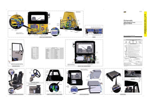
785D Off-Highway Truck Electrical System
27
CONN 8
DMC302-UP MSY255-407
CONN 7 49
A
CONN 17
46
31
34
48
7
41
30
39
33
6
CONN 5 CONN 6
CONN 2 CONN 1
*REAR CAB PANELS REMOVED FOR CLARITY
CONN 15 CONN 14 4
28
5
43
9
3
2
CONN 12 CONN 4
Volume 1 of 6: Cab (Interior and Brake Control) PUBLICATIONS.CAT.COM
DASH
REAR CAB COMPARTMENT
Harness And Wire Electrical Schematic Symbols Symbols
T
Pressure Symbol
Temperature Symbol
Level Symbol
Flow Symbol
Circuit Breaker Symbol
Symbols and Definitions Fuse: A component in an electrical circuit that will open the circuit if too much current flows through it. Switch (Normally Open): A switch that will close at a specified point (temp, press, etc.). The circle indicates that the component has screw terminals and a wire can be disconnected from it. Switch (Normally Closed): A switch that will open at a specified point (temp, press, etc.). No circle indicates that the wire cannot be disconnected from the component.
Connector Location - Volume 1 Connector Number
44
16
Schematic Location
CONN 1
I-16
CONN 2
H-16
CONN 3
A-15
CONN 4
D-15
CONN 5
J-14
CONN 6
I-14
CONN 7
F-14
CONN 8
E-14
CONN 9
A-14
CONN 10
A-13
CONN 11
A-12
CONN 12
B-9
CONN 13 - 12V POWER PORT
B-7
CONN 14
C-7
CONN 15
C-7
CONN 16
J-6
CONN 17
I-6
CONN 18
A-5
CONN 19
H-4
CONN 20
G-4
CONN 21 - COMM RADIO
F-4
CONN 22
B-4
CONN 23
A-4
CONN 24 - TO PAS HARNESS
A-4
CONN 25 - 12V POWER PORT
B-3
The connectors shown in this chart are for harness to harness connectors. Connectors that join a harness to a component are generally located at or near the component. See the Component Location Chart.
Component Location - Volume 1 Schematic Location
Component
Machine Location
Schematic Location
Component
Alarm - VIMS Action
D-5
1
Sensor - Transmission Lever Position
A-7
26
Control - Gauge Cluster
D-1
2
Solenoid - Front Brake Cooling Diverter
E-16
27
Control - Rear Axle Pump
H-16
3
Solenoid - Horn
F-11
28
Control - Speedometer / Tachometer
D-1
4
Suppressor - Horn Solenoid Arc
F-11
29
Control - Steering Bleed
H-16
5
Switch - A/C Enable
F-1
30
Control - VIMS Keypad
C-1
6
Switch - Arc
E-1
31
Control - VIMS Message Center
C-1
7
Switch - Backup Lamp
D-5
32
ECM - Brake
D-12
8
Switch - Blower
F-1
33
Flasher As
G-16
9
Switch - Brake Retract
E-1
34
Ground - Cab
A-16
10
Switch - Dome Lamp
D-7
35
Ground - Chassis
A-16
11
Switch - Fog Lamp
C-5
36
Ground Boss - Rear Cab
H-10
12
Switch - Hazard Lamp
C-5
37
Ground Strap As
A-16
13
Switch - Headlamp
C-5
38
Module - Wiper Delay
I-1
14
Switch - Heated Mirror
E-1
39
Motor - Blower
B-3
15
Switch - Horn
I-1
40
Motor - Power Window
I-3
16
Switch - Key
G-1
41
Motor - Washer
H-1
17
Switch - Ladder Lamp
D-5
42
Motor - Wiper
I-1
18
Switch - Panel Dimmer
F-1
43
Outlet - 24V Power
A-11
19
Switch - Power Window
J-3
44
Resistor - Blower
B-3
20
Switch - Retarder Pressure
J-1
45
Resistor - LH Turn
J-1
21
Switch - Starting Aid
F-1
46
Resistor - RH Turn
J-1
22
Switch - Steering Column
H-1
47
E-16
23
Switch - TCS Test
E-1
48
Sensor - Brake Air Pressure
Ground (Wired): This indicates that the component is connected to a grounded wire. The grounded wire is fastened to the machine.
Machine Location
Sensor - Hoist Lever Position
B-7
24
Switch - Throttle Backup / Lock
F-1
49
Sensor - Throttle Position
B-2
25
Thermostat - HVAC
B-3
50
Ground (Case): This indicates that the component does not have a wire connected to ground. It is grounded by being fastened to the machine. Reed Switch: A switch whose contacts are controlled by a magnet. A magnet closes the contacts of a normally open reed switch; it opens the contacts of a normally closed reed switch. Sender: A component that is used with a temperature or pressure gauge. The sender measures the temperature or pressure. Its resistance changes to give an indication to the gauge of the temperature or pressure.
T
18
Relay (Magnetic Switch): A relay is an electrical component that is activated by electricity. It has a coil that makes an electromagnet when current flows through it. The electromagnet can open or close the switch part of the relay. Solenoid: A solenoid is an electrical component that is activated by electricity. It has a coil that makes an electromagnet when current flows through it. The electromagnet can open or close a valve or move a piece of metal that can do work. Magnetic Latch Solenoid: A magnetic latch solenoid is an electrical component that is activated by electricity and held latched by a permanent magnet. It has two coils (latch and unlatch) that make electromagnet when current flows through them. It also has an internal switch that places the latch coil circuit open at the time the coil latches.
Harness and Wire Symbols Wire, Cable, or Harness Assembly Identification: Includes Harness Identification Letters and Harness Connector Serialization Codes (see sample).
14
Harness Identification Letter(s): (A, B, C, ..., AA, AB, AC, ...)
L-C12 3E-5179
AG-C4 111-7898
L-C12 3E-5179
1
Part Number: for Connector Plug
Harness Connector Serialization Code: The "C" stands for "Connector" and the number indicates which connector in the harness (C1, C2, C3, ...).
Part Number: for Connector Receptacle
2
CONN 20
17 CONNECTOR LOCATIONS SHOWN IN REAR CAB COMPARTMENT SECTION
*FRONT CAB PANELS REMOVED FOR CLARITY
DRIVERS DOOR
5A Plug
CONN 19 45
21
22
*FRONT CAB PANELS REMOVED FOR CLARITY
40
1 2
Deutsch connector: Typical representation of a Deutsch connector. The plug contains all sockets and the receptacle contains all pins.
1 2
Sure-Seal connector: Typical representation of a Sure-Seal connector. The plug and receptacle contain both pins and sockets.
Fuse (5 Amps)
Component Part Number
9X-1123
325-AG135 PK-14 Harness identification code: This example indicates wire group 325, wire 135 in harness "AG".
Wire Gauge* Wire Color
*Wire gauge is shown in AWG (American Wire Gauge) but could also be shown in metric denoted with mm
© 2021 Caterpillar. All Rights Reserved. CAT, CATERPILLAR, LET’S DO THE WORK, their respective logos, “Caterpillar Corporate Yellow”, the “Power Edge” and Cat “Modern Hex” trade dress as well as corporate and product identity used herein, are trademarks of Caterpillar and may not be used without permission.
FRONT CAB COMPARTMENT
CONN 13
Receptacle Pin or Socket Number
CONN 25
CONN 3 CONN 11
47
19 26 50 25 CONN 22
PEDALS
20
35
STEERING WHEEL
10
13
CONN 9
CONN 10 32
*TRIM PARTIALLY REMOVED TO EXPOSE CONNECTOR
11
36
CONN 18
37
CONN 21
HVAC BLOWER BOX
1
CONN 23 CONN 24
24
CENTER CONSOLE AND SEATS
COMM RADIO CONNECTION
CAB TO CHASSIS CONNECTIONS
42
38
15
HVAC BLOWER BOX
HEADLINER
(Dimensions: 56 inches x 35 inches)
CONN 16
42 Page,
UENR2445-03 VOL 1 of 6
29