UENR2449-06 June 2020
C-4
1
Alarm - VIMS Action
C-4
2
Antenna
C-4
Breaker - Air Conditioning Breaker - Alternator
Machine Location
Relay - Diff Fan
F-9
53
Relay - Fog Lamp
F-9
54
3
Relay - Head Lamp
G-9
55
D-8
4
Relay - Heated Mirror
J-9
56
E-8
5
Relay - High Beam
I-9
Connector Location
57
Breaker - Brake Retract
D-8
6
Relay - Main Power
D-9
58
Schematic Location
Connector Number
Cable - Front Camera
A-9
7
Relay - Pre- Lube
G-9
59
Cable - Left Camera
A-9
8
Relay - Seat Belt
H-9
60 61
CONN 1
C-9, I-16
Cable - Rear Camera
A-9
9
Relay - Starting Aid Hold
F-8
CONN 2
B-15, H-16
Cable - Right Camera
A-9
10
Relay - Starting Aid In
G-9
62
CONN 3
E-16
Control - Brake
C-10
11
Relay - Stop Lamp
G-9
63
CONN 4
D-16
Control - RAC
A-13
12
Relay - Window 1
I-9
64
CONN 5
C-16
Control - Steering Bleed
I-16
13
Relay - Window 2
I-9
65
CONN 6
B-16
Control - Transmission (XMSN)
E-11
14
Relay - Wiper
H-9
66
H-13
Control - VIMS
G-11
15
Resistor
C-4
67
CONN 8
F-13
Control Gp - Stairway/Seatbelt Driver
J-16
16
Resistor - Can 2
C-7
68
CONN 9
E-13
Control Gp - XLP RAX Relay
I-16
17
Resistor - Start Aid 1
G-8
69
CONN 10
C-13
Converter - 20A
C-9
18
Resistor - Start Aid 2
G-8
70
CONN 11
C-12
Converter - 20A
I-9
19
Sensor - Brake Air Pressure
G-16
71
Diode - Horn Solenoid
F-16
20
Sensor - Hoist Lever Position
C-12
72
Display - Jumper Camera
A-7
21
Sensor - Throttle Position
C-3
73
Display - Left Hand Digital Payload
I-11
22
Solenoid - Auto Lube
D-10
74
Display GP - Monitor Object Detection
B-7
23
Solenoid - Front Brake Cooling Diverter
G-16
75
CONN 7
46 95
CONN 12 CONN 9
CONN 12
C-7
CONN 13
H-11
CONN 14
H-11
CONN 15
H-11
Flasher
H-16
24
Solenoid - Horn
F-16
76
CONN 16
I-11
Indicator - Body Up
G-1
25
Solenoid - Transmission Lockout
E-10
77
CONN 17
I-10
Indicator - Dash 1
G-2
26
Switch - Air Conditioning On
F-2
78
CONN 18
I-11
Indicator - Dash 2
G-2
27
Switch - Arc
F-1
79
CONN 19
B-6
Indicator - Hi Beam
G-1
28
Switch - Backup Lamp
B-4
80
CONN 20
B-6
Indicator - Left Hand Turn
G-1
29
Switch - Blower
F-2
81
CONN 21
F-6
Indicator - Retarder On
H-2
30
Switch - Brake Retract
E-1
82
CONN 22
H-6
Indicator - Reverse
G-1
31
Switch - Dome Lamp
C-6
83
CONN 23
J-4
Indicator - Right Hand Turn
G-2
32
Switch - Fog Lamp
B-4
84
CONN 24
J-4
Indicator - Seat Belt
G-2
33
Switch - Hazard Lamp
A-4
85
CONN 25
H-4
Indicator - Stairway Down
G-2
34
Switch - Head Lamp
B-4
86
CONN 26
G-4
Indicator - TCS On
G-2
35
Switch - Heated Mirror
E-2
87
CONN 27
B-3
Indicator - VIMS Action
H-2
36
Switch - Horn
I-1
88
CONN 28
B-3
Lighter - Cigar
H-1
37
Switch - Key Start
G-1
89
CONN 29
C-3
Module - Gage Cluster
D-1
38
Switch - Ladder Lamp
C-4
90
CONN 30
C-3
Module - Speedo Tach
D-1
39
Switch - Lockout Brake Pressure
D-10
91
CONN 31
A-6
Module - Vims Key Pad
C-1
40
Switch - Panel Dimmer
Module - VIMS Message Center
D-1
41
Switch - Park Brake
Module - Wiper Delay
J-1
42
Motor - Blower As
C-2
43
Motor - Power Window
J-2
Motor - Washer Motor - Wiper
The connectors shown in this chart are for harness to harness connectors. Connectors that join a harness to a component are generally located at or near the component. See the Component Location Chart.
48 CONN 6 CONN 5 CONN 4 CONN 3 43
100 103 CONN 11
CONN 28 CONN 27 CONN 30 CONN 29
F-2
92
E-10
93
Switch - Power Window
J-2
94
Switch - Retarder
J-1
95
44
Switch - Seat Belt
G-16
96
H-1
45
Switch - Service Brake
D-10
97
I-1
46
Switch - Starting Aid
F-1
98
Outlet - Power 12 V
D-9
47
Switch - Steering Column
I-1
99
Outlet - Power 24V
A-16
48
Switch - Thermostat
C-2
100
Relay - Backup Lamp (CMPD)
F-8
49
Switch - Throttle Backup / Lock
F-1
101
Relay - Backup Lamp (XMSN)
F-8
50
Switch - Traction Control Test
E-1
102
Relay - Brake Retract
H-9
51
Switch - Transmission Lever Position
C-12
103
Relay - CIODS Side Lamp
F-9
52
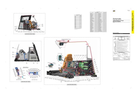
793D Off-Highway Truck Electrical System FDB1606-UP
Volume 1 of 5: Cab Wiring
CAB VIEW (FRONT SIDE) Harness And Wire Electrical Schematic Symbols Symbols T
85
86 84
80
90
1
Pressure Symbol
2
Temperature Symbol
Level Symbol
Flow Symbol
Circuit Breaker Symbol
Symbols and Definitions
68
Fuse: A component in an electrical circuit that will open the circuit if too much current flows through it.
21
Switch (Normally Open): A switch that will close at a specified point (temp, press, etc.). The circle indicates that the component has screw terminals and a wire can be disconnected from it. Switch (Normally Closed): A switch that will open at a specified point (temp, press, etc.). No circle indicates that the wire cannot be disconnected from the component.
7
Ground (Wired): This indicates that the component is connected to a grounded wire. The grounded wire is fastened to the machine.
10
Ground (Case): This indicates that the component does not have a wire connected to ground. It is grounded by being fastened to the machine.
8
Reed Switch: A switch whose contacts are controlled by a magnet. A magnet closes the contacts of a normally open reed switch; it opens the contacts of a normally closed reed switch.
9 23
88
Sender: A component that is used with a temperature or pressure gauge. The sender measures the temperature or pressure. Its resistance changes to give an indication to the gauge of the temperature or pressure.
T
83
Relay (Magnetic Switch): A relay is an electrical component that is activated by electricity. It has a coil that makes an electromagnet when current flows through it. The electromagnet can open or close the switch part of the relay. Solenoid: A solenoid is an electrical component that is activated by electricity. It has a coil that makes an electromagnet when current flows through it. The electromagnet can open or close a valve or move a piece of metal that can do work.
A
Magnetic Latch Solenoid: A magnetic latch solenoid is an electrical component that is activated by electricity and held latched by a permanent magnet. It has two coils (latch and unlatch) that make electromagnet when current flows through them. It also has an internal switch that places the latch coil circuit open at the time the coil latches.
99
Harness and Wire Symbols Wire, Cable, or Harness Assembly Identification: Includes Harness Identification Letters and Harness Connector Serialization Codes (see sample).
(ROTATED FOR CLARITY)
94
49 52
42
6
5
50
CONN 14 CONN 13
47
19
Plug
53
22
44
CONN 16
3
61
74
59
CONN 15
15 71
96
40
32
41
38
35
27
VIEW OF AREA “B”
(ROTATED FOR CLARITY)
36
NOT SHOWN
91
CONN 17
VIEW OF AREA “A” 39
101
98
79
82
77 102 97
41
37
30
26
75
29
34
NOT SHOWN
B
25
39
CONN 25
40
38
28 31
89
33
92
87
78
81
CONN 26
DASH REAR VIEW
CAB VIEW (LEFT SIDE)
DASH FRONT VIEW
72
CONN 10
CONN 31 69
51
57
66
70
65
64
56 60
73
Part Number: for Connector Receptacle
CONN 23 CONN 24 45
20
CONN 21 CONN 22
76
CAB VIEW (REAR SIDE)
58
93
CONN 2
13
17
12
CONN 7
24
16 CONN 8
CONN 1
5A Receptacle Pin or Socket Number
1 2
Deutsch connector: Typical representation of a Deutsch connector. The plug contains all sockets and the receptacle contains all pins.
1 2
Sure-Seal connector: Typical representation of a Sure-Seal connector. The plug and receptacle contain both pins and sockets.
Fuse (5 Amps)
9X-1123
Component Part Number
325-AG135 PK-14 Harness identification code: This example indicates wire group 325, wire 135 in harness "AG".
Wire Gauge* Wire Color
*Wire gauge is shown in AWG (American Wire Gauge) but could also be shown in metric denoted with mm
© 2020 Caterpillar. All Rights Reserved. CAT, CATERPILLAR, LET’S DO THE WORK, their respective logos, “Caterpillar Yellow,” the “Power Edge” and Cat “Modern Hex” trade dress, as well as corporate and product identity used herein, are trademarks of Caterpillar and may not be used without permission.
14
4
CONN 18
L-C12 3E-5179
1
Part Number: for Connector Plug
11
62
55
L-C12 3E-5179
AG-C4 111-7898
Harness Connector Serialization Code: The "C" stands for "Connector" and the number indicates which connector in the harness (C1, C2, C3, ...).
2
54
63
Harness Identification Letter(s): (A, B, C, ..., AA, AB, AC, ...)
CONN 19 CONN 20
(Dimensions: 56 inches x 35 inches)
Alarm - Seat Belt
Schematic Location
Component
42 Page,
Machine Location
Component
UENR2449-06 VOL 1 of 5
Component Location Schematic Location