9
0041
8 Volt DC Supply
0168
Electrical System Voltage
0517
AWD Mode Switch
0600
AWD Hydraulic Oil Temperature
2188
Left Forward Clutch Solenoid
2189
Left Reverse Clutch Solenoid
2190
Right Forward Clutch Solenoid
2191
Right Reverse Clutch Solenoid
2194
AWD Control Dial
2293
Left Front Drive Motor Solenoid
2294
Right Front Drive Motor Solenoid
2295
Left Front Drive Pump Forward Solenoid
2296
Left Front Drive Pump Reverse Solenoid
2297
Right Front Drive Pump Forward Solenoid
2298
Right Front Drive Pump Reverse Solenoid
2319
Left Motor Speed Sensor 1
2320
Left Motor Speed Sensor 2
2321
Right Motor Speed Sensor 1
2322
Right Motor Speed Sensor 2
Data valid but above normal operational range.
1
Data valid but below normal operational range.
2
Data erratic, intermittent, or incorrect.
3
Voltage above normal or shorted high.
4
Voltage below normal or shorted low.
5
Current below normal or open circuit.
6
Current above normal or grounded circuit.
7
Mechanical system not responding properly.
8
Abnormal frequency, pulse width, or period.
9
Abnormal update.
10
Abnormal rate of change.
11
Failure mode not identifiable.
12
Bad device or component.
13
Out of calibration.
14
Parameter failures.
15
Parameter failures.
16
Parameter not available.
17
Module not responding.
18
Sensor supply fault.
19
Condition not met.
20
Parameter failures.
¹The FMI is a diagnostic code that indicates what type of failure has occurred.
Implement Control #3 (MID No. 147) 10
11
CID
13 7
2
1
12
A 15 B
D 8
C 6
10 2 D 7 5
6
C A
1 9 8
12
B 15 11
13
120M Series 2 Motor Grader Electrical System
Component
0041
8 VDC Sensor Power Supply
0168
Electrical System Voltage
0247
SAE J1939 Data Link
0248
Cat Data Link
0262
5 Volt Sensor DC Power Supply
0296
Transmission / Chassis ECM
0358
Implement Pilot Pressure Supply Solenoid
0490
Hydraulic Lockout Switch
0588
Monitoring System Display
0590
Engine Electronic Control Module
0597
Main Hydraulic Pump Discharge Pressure
0600
Hydraulic Oil Temperature Sensor
0615
Machine Articulation Angle Position Sensor
0967
Machine Application
1326
Location Code
1471
Steering Control Position Sensor 1
E0192
Steering System Malfunction
1472
Steering Control Position Sensor 2
E0256
Steering Output Detected in the Wrong Direction
1473
Steering Control Position Sensor 3
E0257
Steering Output Detected with No Command.
1482
10 Volt Sensor DC Power Supply
E0258
No Steering Detected with Command Given.
1558
Electrical Implement Control 2
E0258
No Steering Detected with Command Given.
2113
Operator Present Switch
2143
Electronic Implement Control 3
E0263
Low Main Pump Pressure
2146
Articulation Lever Position Sensor
E0455
Hydraulic Pilot Supply Oil Filter Plugged Secondary Steer Pump No Response
120M2: M921-UP M9C1-UP M9H1-UP R9N1-UP R9W1-UP
Event Codes Implement Control
2147
Automatic Neutral Articulation Switch
E0560
2150
Blade Left Lift Lever Position Sensor
E0562
Steering Lever Has Not Been Aligned to Wheel Steering Angle
2151
Blade Right Lift Lever Position Sensor
E0598
Steering Limited due to Cold Hydraulic Oil
2152
Wheel Lean Control Position Sensor
E0599
Gear Too High for Steering with Cold Oil
2153
Blade Pitch Control Position Sensor
E0795
Machine Speed Excessive for Machine Articulation Angle
2154
Blade Side Shift Lever Position Sensor
E0796
Machine Articulation Angle Limited Due to Machine Speed
2155
Circle Drive Lever Position Sensor
2156
Circle Side Shift Control Position Sensor
E0861
Clock Manual Alignment Required
2160
Blade Left Raise Solenoid Valve
E0878
High Hydraulic Oil Temperature
2161
Blade Right Raise Solenoid Valve
E2085
Invalid Articulation Response Detected
2162
Blade Left Lower Solenoid Valve
2163
Blade Right Lower Solenoid Valve
2165
Blade Side Shift Left Solenoid Valve
2166
Blade Side Shift Right Solenoid Valve
2167
Circle Left Solenoid Valve
2168
Circle Right Solenoid Valve
2169
Circle Side Shift Left Solenoid Valve
2170
Circle Side Shift Right Solenoid Valve
2171
Articulation Left Solenoid Valve
2172
Articulation Right Solenoid Valve
2173
Wheel Lean Left Solenoid Valve
2174
Wheel Lean Right Solenoid Valve
2181
Blade Pitch Forward Solenoid Valve
2182
Blade Pitch Backward Solenoid Valve
2200
Left Steering Cylinder Position Sensor
2201
Right Steering Cylinder Position Sensor
2202
Steering Valve Control Module
2203
Steering Valve Control Module Spool Position Sensor
2204
Auxiliary Lever 1 Position Sensor
2205
Auxiliary Lever 2 Position Sensor
2206
Auxiliary Lever 3 Position Sensor
2207
Auxiliary Lever 4 Position Sensor
2208
Auxiliary Lever 5 Position Sensor
2209
Auxiliary Lever 6 Position Sensor
2210
Auxiliary Lever 7 Position Sensor
2211
Auxiliary Valve 1 - Port B Solenoid
2212
Auxiliary Valve 1 - Port A Solenoid
2213
Auxiliary Valve 2 - Port B Solenoid
2214
Auxiliary Valve 2- Port A Solenoid
2215
Auxiliary Valve 3 - Port B Solenoid
2216
Auxiliary Valve 3 - Port A Solenoid
2217
Auxiliary Valve 4 - Port B Solenoid
2218
Auxiliary Valve 4 - Port A Solenoid
2219
Auxiliary Valve 5 - Port B Solenoid
2220
Auxiliary Valve 5 - Port A Solenoid
2221
Auxiliary Valve 6 - Port B Solenoid
2222
Auxiliary Valve 6 - Port A Solenoid
2223
Auxiliary Valve 7 - Port B Solenoid
2224
Auxiliary Valve 7 - Port A Solenoid
2252
Machine Articulation Angle Sensor 2
2650
Steering Valve Control Module Power Supply
Volume 1 of 4: Cab © 2013 Caterpillar, All Rights Reserved
Printed in U.S.A.
Harness And Wire Electrical Schematic Symbols Symbols
T
Pressure Symbol
Temperature Symbol
Level Symbol
Flow Symbol
Circuit Breaker Symbol
Symbols and Definitions Fuse: A component in an electrical circuit that will open the circuit if too much current flows through it. Switch (Normally Open): A switch that will close at a specified point (temp, press, etc.). The circle indicates that the component has screw terminals and a wire can be disconnected from it. Switch (Normally Closed): A switch that will open at a specified point (temp, press, etc.). No circle indicates that the wire cannot be disconnected from the component. Ground (Wired): This indicates that the component is connected to a grounded wire. The grounded wire is fastened to the machine. Ground (Case): This indicates that the component does not have a wire connected to ground. It is grounded by being fastened to the machine. Reed Switch: A switch whose contacts are controlled by a magnet. A magnet closes the contacts of a normally open reed switch; it opens the contacts of a normally closed reed switch. Sender: A component that is used with a temperature or pressure gauge. The sender measures the temperature or pressure. Its resistance changes to give an indication to the gauge of the temperature or pressure.
Related Electrical Service Manuals
¹ The CID is a diagnostic code that indicates which circuit is faulty.
Title
² The MID is a diagnostic code that indicates which electronic control module diagnosed the fault.
T
Form Number
AWD Control:
RENR9084
Implement Control #3:
RENR9013
Relay (Magnetic Switch): A relay is an electrical component that is activated by electricity. It has a coil that makes an electromagnet when current flows through it. The electromagnet can open or close the switch part of the relay. Solenoid: A solenoid is an electrical component that is activated by electricity. It has a coil that makes an electromagnet when current flows through it. The electromagnet can open or close a valve or move a piece of metal that can do work. Magnetic Latch Solenoid: A magnetic latch solenoid is an electrical component that is activated by electricity and held latched by a permanent magnet. It has two coils (latch and unlatch) that make electromagnet when current flows through them. It also has an internal switch that places the latch coil circuit open at the time the coil latches.
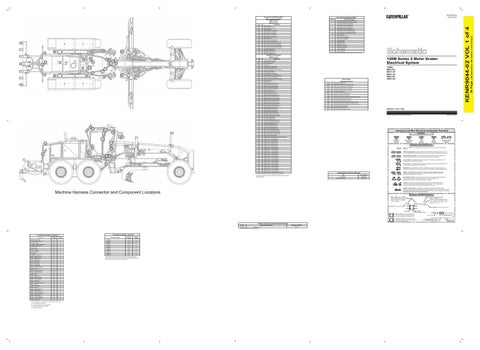
Machine Harness Connector and Component Locations
Harness and Wire Symbols Wire, Cable, or Harness Assembly Identification: Includes Harness Identification Letters and Harness Connector Serialization Codes (see sample).
Harness Identification Letter(s): (A, B, C, ..., AA, AB, AC, ...)
L-C12 3E-5179
AG-C4 111-7898
L-C12 3E-5179
1
Part Number: for Connector Plug
Harness Connector Serialization Code: The "C" stands for "Connector" and the number indicates which connector in the harness (C1, C2, C3, ...).
Part Number: for Connector Receptacle
2 Plug
Receptacle Pin or Socket Number
1 2
Deutsch connector: Typical representation of a Deutsch connector. The plug contains all sockets and the receptacle contains all pins.
1 2
Sure-Seal connector: Typical representation of a Sure-Seal connector. The plug and receptacle contain both pins and sockets.
5A Fuse (5 Amps)
9X-1123
Component Part Number
325-AG135 PK-14
Resistor, Sender and Solenoid Specifications Part No.
Component Description
134-2540 Resistor: Can ¹ At room temperature unless otherwise noted.
Connector Locations - Volume 1
Component Location - Volume 1 Component
Schematic Location
Machine Location
Connector Number
Schematic Location
Machine Location
Camera - Rear Vision
C-8
1
CONN 1
I-13
B
Coil - MSS Exciter ATCH
C-8
A
CONN 2
H-13
12
Controller - AWD
F-11
E
CONN 3
E-13
B
Controller - Product Link ATCH
H-7
2
CONN 4
E-13
B
Controller- Implement #3
I-11
B
CONN 5
E-13
B
Ground - Cab 1
H-12
A
CONN 6
I-10
13
Ground - Cab 2
D-12
E
CONN 7
F-10
B
Lever - Auxiliary 6
G-3
C
CONN 8
D-9
A
Lever - Auxiliary 7
G-3
C
CONN 9
G-9
14
Messenger
F-3
C
CONN 10
E-7
15
Keyreader - MSS ATCH
D-8
A
CONN 11
H-3
B
Mirror - Heated L ATCH
F-7
5
Mirror - Heated R ATCH
F-7
6
Monitor - Rear Vision
C-6
7
Motor - Air Cleaner
E-7
8
Motor - Side Wiper L
I-8
9
Motor - Side Wiper R
I-8
10 C
Port - 12 Volt Auxiliary
F-3
Radio - Product Link ATCH
H-8
2
Resistor - CAN
F-3
D
Switch - Auto Shift On / Off
C-5
C
Sensor - AWD Control Dial
G-12
C
Switch - AWD
G-12
C
Switch - Beacon
F-5
C
Switch - Blade Cushion
G-5
C
Switch - Cab Flood Lamp
E-5
C
Switch - Center Shift Pin
I-5
C
Switch - Defrost Fan
H-5
C
Switch - Differential Lock Floor
F-5
11
Switch - Dimmer
G-5
C
Switch - Flood Lamps
E-5
C
Switch - Hazard
D-5
C
Switch - Head / Tail Lamps
G-5
C
Switch - Heated Mirror
G-5
C
Switch - Heated Side Window
H-5
C
Switch - Implement Lockout
E-5
C
Switch - Regeneration
H-5
C
Switch - Snow Wing Flood
F-5
C
Switch - Throttle Lock Mode
D-5
C
Switch - Throttle Set
D-5
C
Machine locations are repeated for components located close together. A = Located below or inside dash. B = Located inside rear covered compartment. C = Located on right-hand cab column. D = Located in Headliner.
The connectors shown in this chart are for harness to harness connectors. Connectors that join a harness to a component are generally located at or near the component. See the Component Location Chart.
Resistance (Ohms)¹ 120 ± 12
Harness identification code: This example indicates wire group 325, wire 135 in harness "AG".
Wire Gauge Wire Color
(Dimensions: 48 inches x 35 inches)
5
Component
Failure Description
0
KENR9044-02 VOL 1 of 4
CID
Failure Mode Identifiers (FMI)¹ FMI No.
36 Page,
Component Identifiers (CID¹) Module Identifier (MID²) AWD Control (MID No. 075)
KENR9044-02 January 2013