(C280-6) ENGINE
(C280-8) ENGINE
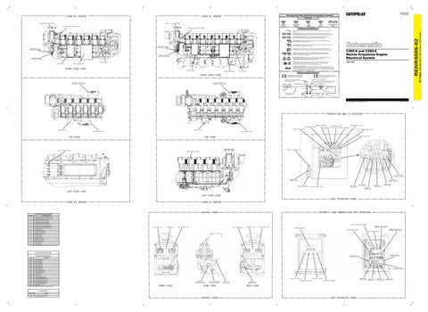
RENR5086-02 August 2007
Harness And Wire Electrical Schematic Symbols Symbols
EXHAUST STACK TEMP SENSOR
T
Pressure Symbol
EXHAUST MANIFOLD TEMP SENSOR
Temperature Symbol
EXHAUST MANIFOLD TEMP SENSOR
Level Symbol
Circuit Breaker Symbol
Flow Symbol
Fuse - A component in an electrical circuit that will open the circuit if too much current flows through it. Switch (Normally Open): A switch that will close at a specified point (temp, press, etc.). The circle indicates that the component has screw terminals and a wire can be disconnected from it.
RENR5086-02
Switch (Normally Closed): A switch that will open at a specified point (temp, press, etc.). No circle indicates that the wire cannot be disconnected from the component. Ground (Wired): This indicates that the component is connected to a grounded wire. The grounded wire is fastened to the machine. Ground (Case): This indicates that the component does not have a wire connected to ground. It is grounded by being fastened to the machine.
SECONDARY ENGINE SPEED/TIMING SENSOR
SECONDARY ENGINE SPEED/TIMING SENSOR
Reed Switch: A switch whose contacts are controlled by a magnet. A magnet closes the contacts of a normally open reed switch; it opens the contacts of a normally closed reed switch.
C280-6 and C280-8 Marine Propulsion Engine Electrical System
Sender: A component that is used with a temperature or pressure gauge. The sender measures the temperature or pressure. Its resistance changes to give an indication to the gauge of the temperature or pressure.
T
PRIMARY ENGINE SPEED/TIMING SENSOR
Relay (Magnetic Switch): A relay is an electrical component that is activated by electricity. It has a coil that makes an electromagnet when current flows through it. The electromagnet can open or close the switch part of the relay.
PRIMARY ENGINE SPEED/TIMING SENSOR RAIL HARNESS CONTROL PANEL
LDL1-104
Solenoid: A solenoid is an electrical component that is activated by electricity. It has a coil that makes an electromagnet when current flows through it. The electromagnet can open or close a valve or move a piece of metal that can do work.
USER INTERFACE BOX
MAGNETIC LATCH SOLENOID - A magnetic latch solenoid is an electrical component that is activated by electricity and held latched by a permanent magnet. It has two coils (latch and unlatch) that make electromagnet when current flows through them. It also has an internal switch that places the latch coil circuit open at the time the coil latches.
RIGHT SIDE VIEW CONTROL PANEL
USER INTERFACE BOX
RAIL HARNESS
Harness and Wire Symbols
RIGHT SIDE VIEW
1 2
1 2
Deutsch connector: Typical representation of a Deutsch connector. The plug contains all sockets and the receptacle contains all pins.
Harness Identification Letter(s): (A, B, C, ..., AA, AB, AC, ...)
Wire, Cable, or Harness Assembly Identification: Includes Harness Identification Letters and Harness Connector Serialization Codes
ALTERNATE LOCATION FOR THE USER INTERFACE BOX
ALTERNATE LOCATION FOR THE USER INTERFACE BOX
Part Number for Connector Plug
C-C4 AG-C3 130-6795 130-6795
Harness Connector Serialization Code: The "C" stands for "Connector" and the number indicates which connector in the harness. (C1, C2, C3, .....)
L-C12 3E-5179
AG-C4 111-7898
Part Number For Connector Recepticle
1
325-AG135 PK-14 Socket
Pin
Sure-Seal connector: Typical representation of a Sure-Seal connector. The plug and receptacle contain both pins and sockets.
5A
Receptacle Pin or Socket Number
Single Wire Connector
9X-1123
Component Part Number
Plug
200-L32 BK-14
2
Harness identification code: This example indicates wire 135 in harness "AG".
Fuse (5 Amps)
Ground Connection
Circuit Identification Number
Wire Gauge
Wire Color
© 2007 Caterpillar, All Rights Reserved
Printed in U.S.A.
PRODUCTION MMS II OFFERING
DIAGNOSTIC PRIMARY DIAGNOSTIC SECONDARY
SECONDARY ECM ACTIVE
GENERAL ALARM RELAY
SPEED CONTROL MODULE
CONTROL PANEL
CONTROL PANEL
SHUTDOWN NOTIFY RELAY
SECONDARY ECM READY
SECONDARY READY RELAY
USER INTERFACE BOX
USER INTERFACE BOX
TOP VIEW
SECONDARY ACTIVE RELAY
TOP VIEW
SERVICE TOOL CONNECTOR
BOOST PRESSURE SENSOR BOOST PRESSURE SENSOR
ISOLATOR FOR SECONDARY THROTTLE CONNECTOR TO CONTROL PANEL
ISOLATOR FOR PRIMARY THROTTLE
CUSTOMER CONNECTOR
BREAKER FOR MAIN POWER
SHUTOFF DRIVER DIODE
ISOLATOR FOR LOAD FEEDBACK
BREAKER FOR SECONDARY ECM
BREAKER FOR OTHER LOADS
BREAKER FOR PRIMARY ECM
LEFT SIDE VIEW LEFT SIDE VIEW USER INTERFACE PANEL (C280-6) ENGINE
(C280-8) ENGINE
RETROFIT AND PRODUCTION ECP OFFERING
CONTROL PANEL Failure Mode Identifiers (FMI)¹ FMI No.
Failure Description
0
Data valid but above normal operational range.
1
Data valid but below normal operational range.
2
Data erratic, intermittent, or incorrect.
3
Voltage above normal or shorted high.
4
Voltage below normal or shorted low.
5
Current below normal or open circuit.
6
Current above normal or grounded circuit.
7
Mechanical system not responding properly.
8
Abnormal frequency, pulse width, or period.
9
Abnormal update.
10
Abnormal rate of change.
11
Failure mode not identifiable.
12
Bad device or component.
13
Out of calibration.
14
Parameter failures.
15
Parameter failures.
SPEED CONTROL POTENTIOMETER J1/P1 PRIMARY ECM
PRIMARY ECM
J2/P2 PRIMARY ECM
J1/P1 SECONDARY ECM
SECONDARY ECM
J2/P2 SECONDARY ECM
GENERAL ALARM RELAY OR SHUTDOWN NOTIFY RELAY
MESSENGER DISPLAY SPEED CONTROL MODULE
16
Parameter not available.
17
Module not responding.
18
Sensor supply fault.
19
Condition not met.
20
Parameter failures.
LOCAL/REMOTE SWITCH
GENERAL ALARM RELAY OR SHUTDOWN NOTIFY RELAY
¹The FMI is a diagnostic code that indicates what type of failure has occurred.
Component Identifiers (CID¹)
CID
Component
0001
Injector Cylinder #1
0002
Injector Cylinder #2
0003
Injector Cylinder #3
0004
Injector Cylinder #4
0005
Injector Cylinder #5
0006
Injector Cylinder #6
0007
Injector Cylinder #7
0008
Injector Cylinder #8
0091
Throttle Position Sensor
0168
Electrical System Voltage
0190
Engine Speed Sensor
0248
CAT Data Link
ISOLATOR FOR SECONDARY THROTTLE
0253
Personality Mode
0262
5 Volt Sensor Power Supply
0268
Programmable Parameter Fault
0273
Turbocharger Outlet Pressure Sensor
0274
Atmospheric Pressure Sensor
0342
Secondary Engine Speed Sensor
1249
Secondary Throttle Position
1495 Injector Codes ¹ The CID is a diagnostic code that indicates which circuit is faulty.
SECONDARY ECM READY
DIAGNOSTIC PRIMARY
SECONDARY ECM ACTIVE CONNECTOR TO USER INTERFACE BOX
FRONT VIEW
FOR THR ATMOSPHERIC PRESSURE SENSOR
SIDE VIEW
CONNECT TO RAIL HARNESS
DIAGNOSTIC SECONDARY
ATMOSPHERIC PRESSURE SENSOR
REAR VIEW
Event Codes Event Code
ISOLATOR FOR PRIMARY THROTTLE
ISOLATOR FOR LOAD FEEDBACK
Engine Monitoring System
Condition
E043
Low System Voltage Warning
E190
Engine Overspeed Warning
CONTROL PANEL
USER INTERFACE PANEL
BREAKER FOR MAIN POWER
BREAKER FOR PRIMARY ECM
BREAKER FOR SECONDARY ECM
BREAKER FOR OTHER LOADS
(Dimensions: 48 inches x 35 inches)
Symbols and Definitions
36 Page,
EXHAUST STACK TEMP SENSOR