Customer Connector J61 Customer Connector J61
J1939 Termination Resistor P67
160-7689
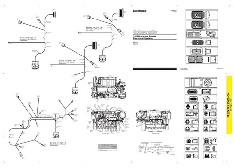
RENR2242-04 June 2004
Service Tool Connector J60
J1939 Termination Resistor J67 Service Tool Connector J60
SPLICE A234 SPLICE K900 SPLICE K990
160-7690
SPLICE A234(B) SPLICE K900(B) SPLICE K990(B)
SPLICE J906
Harness 194-1592 -04 Connector and Splice Locations SPLICE 101 SPLICE 229(B) SPLICE J906
SPLICE 945
103-0213
1
Start Relay P515 SPLICE 944
3126B Marine Engine Electrical System
Data Booster P64 NOTE H SPLICE 945
Harness 233-8335 -03 Connector and Splice Locations
SPLICE 229
2
3
4
5
6
7
8
9 10 11 12 13 14
15 16 17 18 19 20 21
22 23 24 25 26 27 28
29 30 31 32 33 34 35
36 37 38 39 40 41 42
43 44 45 46 47 48 49
50 51 52 53 54 55 56
57 58 59 60 61 62 63
64 65 66 67 68 69 70
9X-4391
14 13 12 11 10 9
Service Tool Connector J60
SPLICE 944
Start Relay P515
9ZF1-UP 3GS1-UP
Customer Connector J61
8
7
6
5
4
3
2
1
28 27 26 25 24 23 22
21 20 19 18 17 16 15
42 41 40 39 38 37 36
35 34 33 32 31 30 29
56 55 54 53 52 51 50
49 48 47 46 45 44 43
70 69 68 67 66 65 64
63 62 61 60 59 58 57
SPLICE 229(A)
9X-1343
SPLICE A234(A) SPLICE K900(A) SPLICE K990(A)
1
5
6
10
11
15
16
20
21
25
26
30
31
35
36
40
8T-9834
SPLICE J906
Harness 177-4273 -03 Connector and Splice Locations Start Relay P515
10
6
5
1
20
16
15
11
30
26
25
21
40
36
35
31
ECM Connector P1
SPLICE 945
SPLICE 944
Data Booster P64
Printed in U.S.A.
© 2004 Caterpillar All Rights Reserved
ECM Connector P1 SPLICE 229
COOLANT LEVEL SENSOR P800 (OPTIONAL)
Inlet Air Heater Lamp J648
8T-8736
D E ENGINE COOLANT TEMPERATURE SENSOR P100
C A
F
B J
G H
2
1
155-2252
Inlet Air Heater Relay P501
9
4
3
8
5
7
6
A
B
ECM Connector P1
Engine Oil Temperature Sensor J101 NOTE Y
2
10
3E-5179
Inlet Manifold Temperature Sensor P103
8
9
6
5
4
10 11 12
TOP VIEW
ENGINE OIL TEMPERATURE SENSOR J101 NOTE Y
NOT USED
7
3
2
1
169-8670
Fuel Level Sensor Connector P803 NOTE S
Boost (Turbo Outlet) Pressure Sensor J200
UNIT INJECTOR HARNESS CONNECTOR J300/P300
INJECTION ACTUATION PRESSURE SENSOR J204
BOOST PRESSURE SENSOR J200
INLET MANIFOLD TEMPERATURE SENSOR P103
ENGINE OIL PRESSURE SENSOR J201
B
A
TIMING CALIBRATION (TC) PROBE CONNECTOR P400
INLET AIR HEATER RELAY P501
FUEL TEMPERATURE SENSOR P105 (OPTIONAL)
155-2267
C
C
3E-3370
174-0502
NOT USED
B
Timing Calibration (TC) Probe Connector P400
SPLICE G833
Transmission Oil Pressure Connector P212
SPLICE N940
SPLICE 997(B)
B
A
A
A
B
C
C
SPLICE 993(B)
155-2269
Primary Engine Speed/Timing Sensor P401 Secondary Engine Speed/Timing Sensor P402
SPLICE 997(A)
Engine Oil Pressure Sensor J201
SPLICE 993(A)
Transmission Oil Temperature Connector J137
INJECTION ACTUATION PRESSURE CONTROL VALVE P500
SERVICE TOOL CONNECTOR J60
PRIMARY ENGINE SPEED/TIMING SENSOR P401
TRANSMISSION OIL TEMPERATURE CONNECTOR J137
1
2
CUSTOMER CONNECTOR J61
SPLICE L983
3E-3363
2
2
1
FUEL LEVEL SENSOR CONNECTOR P803 (OPTIONAL)
SECONDARY ENGINE SPEED/TIMING SENSOR P402
Engine Coolant Temperature Sensor P100
1
2
3E-3364
START RELAY CONNECTOR P515
1
Fuel Temperature Sensor P105
3E-3360
TRANSMISSION OIL PRESSURE CONNECTOR P212
SPLICE N941
LEFT SIDE VIEW
ECM CONNECTOR P2
ECM CONNECTOR P1
RIGHT SIDE VIEW
SPLICE L984 SPLICE L985
3E-3373
3E-3382
ECM Connector P2
Harness And Wire Symbols Wire, Cable, or Harness Assembly Identification
Related Electrical Service Manuals Title
Form Number RENR2243
Systems Operation / Testing and Adjusting
RENR2248
Electronic Installation Guide (Engine)
REHS1187
Installation Guide (Marine Engine Electronic Displays)
1
325-AG135 PK-14 Pin
Socket
SENR5002
Single Wire Connector
J274 3E-5179
P274 111-7898
Wire Color
Ground Circuit Connection Number Identification
2
4
3
140-7339
325-A135 PK-14 Receptacle
B
B
Fuse
Plug 2
200-L32 BK-14 111-2416
Pin or Socket Number
105-9344
100-3320
Component Part Number A
Injector Harness Connector J300
1
5
153-9693
Part Number For Connector Assembly
A
Wire Gauge
6
B
Troubleshooting
J174 P174 130-6795 130-6795
4 3
A
Injection Actuation Pressure Sensor J204
Engine Coolant Level Sensor P800
Harness 194-1591 -06 Connector and Splice Locations
Harness identification code This example indicates wire 135 in harness "AG".
1 2
B
A
B
30 Page, JVD
1
Injection Actuation Pressure Control Valve P500
11
RENR2242-04
12