Component Location
Connector Location¹ Schematic Location
Connector Number
Machine Location
Component
CONN 1 A-8 6 CONN 2 B-8 26 CONN 3 B-8 26 CONN 4 B-8 26 CONN 5 B-9 26 CONN 6 B-9 6 CONN 7 B-9 6 CONN 8 B-6 6 CONN 9 B-6 6 CONN 10 C-6 26 CONN 11 A-7 8 CONN 12 A-6 8 CONN 13 E-4 27 CONN 14 C-4 26 CONN 15 B-4 26 CONN 16 B-4 26 CONN 17 A-4 26 ¹ The connectors shown in this chart are for harness to harness connectors. Connectors that join a harness to a component are generally located at or near a component. See the Component Location Chart.
19
22 27
4 12
11
9
13 21
5
B
18 17
23
14
1
7 26
2 15
20
25
8
10
3
6
A
Related Electrical Service Manuals Title
Form No.
Alternator
SENR3685
3E-7295 (Std 55A) 9X-0341 (Att 90A)
4
Starting Motor 111-9860
SENR3828
Transmission and Shift Control
SENR5856
12
11 10
9
5
Machine Location
Alarm - Backup A-9 Alarm - Park Brake C-6 Alternator B-2 Battery A-3 Beacon - Fixed E-9 Beacon - Fixed F-9 Beacon - Magnetic F-9 Breaker - Acc Relay B-8 Control - Shift D-5 Control - Transmission A-5 Diode Block As E-5 Flasher C-7 Fuses F-5 Fuses C-9, D-9 Gauge - Converter Temp D-8 Gauge - Coolant Temp E-8 Gauge - Fuel D-9 Gauge - Voltmeter D-8 Horn - Forward A-2 Lamp - Action A-7 Lamp - Air Inlet Heater D-7 Lamp - Brake Fluid D-3 Lamp - Coolant Temp E-3 Lamp - Engine Oil Pressure E-3 Lamp - Front Drive D-3 Lamp - Left Turn Indicator E-3 Lamp - Park Brake E-3 Lamp - Primary Steer D-3 Lamp - Right Turn Indicator E-3 Lamp - Start Aid D-7 Meter - Service D-8 Motor - Blower D-4 Motor - Blower E-6 Motor - Fan As F-7 Motor - Wiper (Front) E-3 Motor - Wiper (Rear) E-9 Relay - A/C C-9 Relay - Air Inlet Heater B-2 Relay - Accessory C-7 Relay - Cab C-9 Relay - Lamp Check C-7 Relay - Main C-8 Relay - Park Brake Alarm C-7 Relay - Start C-8 Resistor - Blower (A/C) E-5 Machine location are repeated for components located close together A = Operator Compartment - Right Console B = Operator Compartment - Front Dash
16
24
Schematic Location
B
1 A 2 3 4 4 4 A 5 6 B A A A A A A A 7 8 A B B B B B B B B A A 9 9 10 9 11 A 14 A A A A A A 12
Component Resistor - Blower (Heater) Resistor - Key Start Sender - Converter Sender - Coolant Sender - Fuel Solenoid - A/C Clutch Solenoid - Bucket Positioner Solenoid - Engine Shutdown Solenoid - Front Drive Solenoid - No. 1 (Reverse) Solenoid - No. 2 (Forward) Solenoid - No. 3 (Fourth Gear) Solenoid - No. 4 (First Gear) Solenoid - No. 5 (Second Gear) Solenoid - No. 6 (Third Gear) Solenoid - Start Aid Starter Switch - Beacon Switch - Blower Switch - Brake Switch - Brake (2) Switch - Coolant Switch - Engine Oil Switch - Flood Lamp (Front) Switch - Flood Lamp (Rear) Switch - Flood Lamp (Rear) Switch - Forward Horn Switch - Front Drive Switch - Heater Blower Switch - Key Start Switch - Park Brake Switch - Primary Steer Switch - Refrigerant Switch - Return to Dig Switch - Running Lamp Switch - Start Aid Switch - Start Aid Switch - Thermostat Switch - Turn/Hazard Switch - Wiper (Front) Switch - Wiper (Rear) Switch - XMSN Neutralizer Tachometer As.-Timer
Schematic Location
Machine Location
D-4 D-7 B-2 C-1 F-4 D-1 A-4 E-2 C-3 B-2 C-2 C-2 C-2 C-2 C-2 A-2 A-2 E-7 F-5 C-2 E-4 C-2 C-2 E-7 E-7 E-9 D-3 D-3 E-4 D-7 D-6 C-3 F-1 A-3 E-7 C-2 D-7 E-6 F-3 D-6 E-6 B-6 D-9 C-7
13 A 14 15 16 17 8 18 19 14 14 14 14 14 14 7 20 A 9 21 22 15 23 A A A B B 13 A 24 B 17 25 A A A 9 B A A A A A
SENR5852-02 June 2003
446B Backhoe Loader Electrical System 5BL1500-2499
27
A
13
7 17
24
6
22 8
21 14 25 16
1
CID-FMI
11
No Active Faults
31 32 33 34 35 36
No Inactive Faults 641-05 642-05 643-05 644-05 645-05 646-05
37
683-05
41 42 43 44 45 46
641-06 642-06 643-06 644-06 645-06 646-06
12
47
683-06
51 52 53 54 55 56
641-03 642-03 643-03 644-03 645-03 646-03
57
683-03
69 71 72 73
668-02 168-00 168-01 650-02
3 26
20
2
15
23
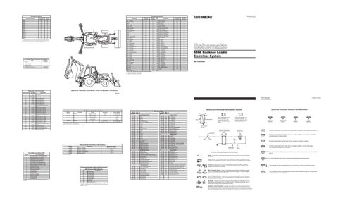
Machine Harness Connector And Component Locations
Diagnostic Code Conversion Code Flashed
19
18
Description
D85129
Not Applicable Not Applicable Solenoid 1 Open Circuit Solenoid 2 Open Circuit Solenoid 3 Open Circuit Solenoid 4 Open Circuit Solenoid 5 Open Circuit Solenoid 6 Open Circuit Parking Brake Alarm Relay Open Circuit Solenoid 1 Short to Ground Solenoid 2 Short to Ground Solenoid 3 Short to Ground Solenoid 4 Short to Ground Solenoid 5 Short to Ground Solenoid 6 Short to Ground Parking Brake Alarm Relay Short to Ground Solenoid 1 Short to + Battery Solenoid 2 Short to + Battery Solenoid 3 Short to + Battery Solenoid 4 Short to + Battery Solenoid 5 Short to + Battery Solenoid 6 Short to + Battery Parking Brake Alarm Relay Short to Battery Invalid Shift Lever Input System Voltage Above Normal System Voltage Below Normal Invalid Harness Code
Harness And Wire Electrical Schematic Symbols Off Machine Switch Specification Part No. 9W-1519
Function
Actuate
Deactuate
Contact Position
Coolant
689 kPa ± 103 kPa 415 kPa 1-2 Normally Open (100 psi ± 14.9 psi) (60.2 psi) 1-3 Normally Closed 9X-3395 Primary Steer .25Nm to .43Nm -Normally (.19 lb ft to .32 lb ft) -Open 114-5333 Refrigerant Pressure 275 to 1750 kpa¹ -Normally ² (40 to 255 psi) -Open 138-7008 Start Aid 0 °F 10 °F to 25 °F A-C Normally Closed 32 °C (-12.2 °C to -3.9 °C) A-B Normally Open ¹ A hysteresis band exists: with increasing pressure the closed condition can be maintained up to 2800 kpa (405 psi), with decreasing pressure the closed condition can be maintained down to 170 kpa (25 psi). ² Contact position at the contacts of the harness connector.
Part No
FMI No.
Failure Description
0 Data valid but above normal operational range. 1 Data valid but below normal operational range. 2 Data erratic, intermittent, or incorrect. 3 Voltage above normal or shorted high. 4 Voltage below normal or shorted low. 5 Current below normal or open circuit. 6 Current above normal or grounded circuit. 7 Mechanical system not responding properly. 8 Abnormal frequency, pulse width, or period. 9 Abnormal update. 10 Abnormal rate of change. 11 Failure mode not identifiable. 12 Bad device or component. 13 Out of calibration. 14 Parameter failures. 15 Parameter failures. 16 Parameter not available. 17 Module not responding. 18 Sensor supply fault. 19 Condition not met. 20 Parameter failures. The FMI is a diagnostic code that indicates what type of failure has occurred.
7T-3828 8C-4110 102-346 3E-8620 6T-6885 3T-9493 ¹At room temperature.
Component
Resistance (Ohms)¹
Resistor - A/C Blower Resistor - Key Switch Solenoid - A/C Clutch Solenoid - Bucket Positioner Solenoid - Front Drive Solenoid - Start Aid
Overall - 1.0 ± .1; Tap - .5 22 ± 1.1 3.5 ± 0.15 32.1 8.9 ± 0.3 1.5
Component Identifier (CID¹) List Trans Control MID14(Product) MID13(Retrofit) CID
Electrical Schematic Symbols And Definitions
Wire Description
Resistor,Sender, And Solenoid Specifications
Failure Mode Identifiers (FMI)
Printed in U.S.A.
© 2003 Caterpillar All Rights Reserved
Component
168 Electrical System 641 Solenoid #1 (Rev) 642 Solenoid #2 (Fwd) 643 Solenoid #3 (Sp4) 644 Solenoid #4 (Sp1) 645 Solenoid #5 (Sp2) 646 Solenoid #6 (Sp3) 650 Harness Code 668 Shift Lever 683 Parking Brake Alarm ¹ The CID is a diagnostic code that indicates which component is faulty. ² The MID is a diagnostic code that indicates which electronic control module diagnosed the fault.
Wire Number
Wire Color
101 102 103 105 109 112 113 116 118 119 120 121 122 123 124 126 128 143 157 161 194
RD BU YL BR OR PU OR BR GY PK YL YL BU WH GN PK PK BR YL PK GN
200 202 276 277 278 279 280 281
BK BK BK BK BK BK BK BK
301 303 304 306 307 308 309 310 311 321 322 326
BU BR WH GN OR YL GY PU WH BR GY PU
405 406 409 415 415 417 419 441 443 447 450 483
GY PU OR GN GN GY YL OR YL PK YL BR
Description Power Distribution Circuits Bat (+) Hd Lmp Aux Ckt KEY SW Alt Output (+) Term. Main Power Rly Output Opr Mon Panel VMIS B+ Switched Aux Ckt Aux Ckt Aux Ckt Aux Ckt Bckp Alarm to Lamp Aux Ckt Aux Ckt A/C XMSN Ctrl Aux Ckt Aux Ckt Aux Ckt Aux Ckt Aux Ckt Ground Circuits Main Chassis XMSN Ctrl XMSN Ctrl Ident Code 0 XMSN Ctrl Ident Code 1 XMSN Ctrl Ident Code 2 XMSN Ctrl Ident Code 3 XMSN Ctrl Ident Code 4 XMSN Ctrl Ident Code 5 Basic Machine Circuits Starter No. 1 Sol Key Sw Acc Position Starter Rly No. 1 Output Starter Rly Coil to Neut Start Sw or Key Sw Key Sw to Neut Start Sw or VMIS Sensor Module Main Power Rly Coil Alt Regulator Term. Start Aid Sw to Start Aid Sol Start Aid Sol to Temp Sw Bckp Alarm Lamp TRAVEL Alarm Warning Horn (Forward) Key Sw "C" Term. Monitoring Circuits Opr Mon Oil Press. (Lo Setting) Opr Mon Coolant Temp Opr Mon Neut Opr Mon Test Sw Opr Mon Test Sw Primary Ster SW Opr Mon Parking Brake Eng Coolant Temp Gauge Power Train Temp Gauge Fuel Level Gauge Tach Sender (+) Brake Fluid Level
Wire Number
Wire Color
500 501 502 503 504 505 513 515 516 517 520 521 522 536 552 568
BR GN OR BR YL BU OR GY GN BU WH YL WH WH WH GN
603 604 605 606 608 610 614 617 618 620 630 639 640
PK OR YL GY GN OR PU BR YL WH GY WH GN
720 751 752 754 755 762 900 901 944 945 958 965 966 968 969 970 971 972 975 C920 E999
PU GN YL BU OR YL PU WH OR BR YL WH GY BR YL GN YL BU WH GY GN
Description Accessory Circuits Wiper - Front (Park) Wiper - Front (Lo) Wiper - Front (Hi) Wiper - Rear (Park) Wiper - Rear (Lo) Wiper - Rear (Hi) A/C Compressor/Refrigerant Press Sw Blower Motor (Hi) Blower Motor (Medium) Blower Motor (Lo) Opr A/C Sw to Thermostat/Fuse A/C Sw to Refrigerant Sw A/C Clutch to Thermostat Sw Hazard Sw to Turn Sw Four Wheel Drive Sol Warning Buzzer to Diodes Lighting Circuits Rotary Beacon Stop Lamp Turn Lamp - Left Turn Lamp - Right Flood Lamp - Rear Head Lamp Basic Park/Tail/Dash Lamp Tail/Position Lamp - Left (Road Pkg)/Width Tail/Position Lamp - Right (Road Pkg)/Width Flood Lamp - Front Flood Lamp Rear (Attach) Left Hand Stop/Tail Lamp Right Hand Stop/Tail Lamp Control Circuits XMSN Brake Sw XMSN Shift Sol No. 1 or 3 XMSN Shift Sol No. 2 XMSN Shift Sol No. 3 or 1 XMSN Shift Sol No. 4 or 5 Bucket Positioner Sol Sw XMSN Shift Sol No. 5 or 4 XMSN Shift Sol No. 6 Data Link + (CAT) Data Link - (CAT) Relay Logic Trans Sol 1 Sw to Gnd (Fwd Hi:CST, Rev:LRT) Trans Sol 3 Sw to Gnd (Fwd Lo:CST, 4th:LRT) Trans Sol 2 Sw to Gnd (Rev:CST, Fwd:LRT) Trans Sol 3 Sw to B+ :CST, for LRT Sol 2 Trans Sol 4 Sw to Gnd (Spd1:CST, 3rd:LRT) Trans Sol 5 Sw to Gnd Trans Sol 6 Sw to Gnd (Spd3:CST, 1st:LRT) Cst Autoshift - Sol Return Action Lamp - Control Reverse Parity (Sol 1 to B+)
A
AA
Typical representation of a Deutsch connector. The plug contains all sockets and the receptacle contains all pins.
Receptacle
Plug
1 2
1 2
1
2
Typical representation of a Sure-Seal connector. The plugand receptacle contain both pins and sockets.
T
Pressure Symbol
Temperature Symbol
Level Symbol
Flow Symbol
Pin or Socket Number Wire, Cable, or Harness Assembly Identification
Component Part Number
Normally open switch that will close with an increase of a specific condition (temp-press-etc.).
Single Wire Connector C
A
A 325-PK-14
Pin
AA 1
9X-1123 325-PK-14
Normally open switch that is closed due to an applied condition, and will open again with a specific decrease in that condition.
Wire Color
Socket
Normally closed switch that will open with an increase of a specific condition. 2
200-BK-14
Circuit Number Identification
Wire Gauge
Electrical Schematic Symbols And Definitions
Normally closed switch that is open due to an applied condition, and will close again with a specific decrease in that condition.
The circle indicates that the component has screw terminals and a wire can be disconnected from it.
FUSE - A component in an electrical circuit that will open the circuit if too much current flows through it. REED SWITCH - A switch whose contacts are controlled by a magnet. A magnet closes the contacts of a normally open reed switch; it opens the contacts of a normally closed reed switch.
T
SENDER - A component that is used with a temperature or pressure gauge. The sender measures the temperature or pressure. Its resistance changes to give an indication to the gauge of the temperature or pressure.
RELAY (Magnetic Switch) - A relay is an electrical component that is activated by electricity. It has a coil that makes an electromagnet when current flows through it. The electromagnet can open or close the switch part of the relay. CIRCUIT BREAKER (C/B) - A component in an electrical circuit that will open the circuit if too much current flows through it. This does not destroy the circuit breaker and it can be reset to become part of the circuit again. SOLENOID - A solenoid is an electrical component that is activated by electricity. It has a coil that makes an electromagnet when current flows through it. The electromagnet can open or close a valve or move a piece of metal that can do work. MAGNETIC LATCH SOLENOID - A magnetic latch solenoid is an electrical component that is activated by electricity and held latch by a permanent magnet. It has two coils (latch and unlatch) that make electromagnet when current flows through them. It also has an internal switch that places the latch coil circuit open at the time the coil latches.
No circle indicates that the wire cannot be disconnected from the component.
This indicates that the component has a wire connected to it that is connected to ground.
This indicates that the component does not have a wire connected to ground. It is grounded by being fastened to the machine.