UENR5835-02 June 2020
Wire Description
RD
103
RD
Wire Color
Unswitched Battery (+)
518
OR
Switch To Hazard Flasher
Unswitched Battery (+)
521
YL
Fan Speed Switch To A/C Pressure Switch
Power Circuits
Description
Accessory Circuits (Continued)
Component Location
104
RD
Starter Motor
522
WH
A/C Clutch To Thermostat Switch
105
RD
Key Switch
537
GN
Turn Signal Switch To Flasher
110
RD
Flasher
552
WH
All Wheel Drive Solenoid
111
RD
Forward Horn
564
GY
Rear Wiper Interrupt Switch To Wiper Switch
Alarm - Action
PU
Main Power Relay Output
568
GN
Warning Buzzer To Diodes
C-14
2
112
Alarm - Backup
3
113
OR
Operator Panel
569
PK
H-14 B-14
115
RD
Accessory Power Port
5
116
BR
Power Rear Lamp
G-2 C-2
603
Power Rear Lamp - ATCH
Accessory Power Port
49
A/C Switch Jumper #2 Lighting Circuits
PK
604
Component
OR
Alarm - Feature Flasher
Rotary Beacon Lamp #1
Fuse Block
Stop Lamps
Module Gp - Display
117
YL
118
GY
Power Front Wiper
605
YL
Turn Lamps - Left
119
PK
Power Rear Wiper
606
GY
Turn Lamps - Right
Schematic Location D-11
Machine Location 1
4 6 7
Ground - Lower Cab
D-14 D-5 D-5
9
Ground - Upper Cab
G-14
10
Ground - Control
8
122
BU
Power HVAC
607
PK
Flood Lamps - Front #1
Handle - FNR Shift
E-8
11
123
WH
Fuel Lift Pump Relay
608
GN
Flood Lamps - Rear #1
Motor - Front Wiper
G-12
12
124
GN
A/C Clutch
614
PU
Tail / Position / Dash Lamps
Motor - Rear Wiper
G-14
13
125
OR
Product Link Radio
617
BR
Tail / Position Lamp - Left
Motor - Seat
I-4
14
126
RD
Grade Check ECM
618
YL
Tail / Position Lamp - Right
Relay - AWD Brake
D-1
15
127
OR
Laser Grade Check
620
WH
Flood Lamps - Engine
Relay - Backup Alarm
G-1
16
133
OR
Inclinometer
630
GY
Flood Lamps - Rear Attachment #1
668
BU
136
GN
Supplemental Steering Control
143
BR
Differential Lock Solenoid
144
GN
Beacon
702
OR
Transmission Brake Switch Jumper
146
GY
Front Flood Lamp Relay
708
YL
Transmission Hold Switch
157
YL
Front Lamp - ATCH
720
PU
Transmission Brake Switch
158
BR
Front Lamp
752
YL
Transmission Shift Solenoid 2
180
GN
754
BU
Transmission Shift Solenoid 3 Or 1
762
YL
Bucket Positioner Solenoid Switch
200
BK
202
BK
304
WH
Operator Seat Ground Circuits Main Chassis Accugrade Power Module Basic Machine Circuits
CONN 21
Switch To Tail / Position Lamps Relay #2 Control Circuits
CONN 18 CONN 14
Relay - Fuel Lift Pump
H-1
17
Relay - Horn
G-1
18
Relay - HVAC Power
I-1
19
Relay - Position Lamp
F-1
20
Relay - Power Module #1
I-2
21
Relay - Power Module #2
I-1
22
Relay - Ride Control
D-1
23
Relay - Start
H-2
24
Relay - Start Aid
H-1
25
Resistor - Terminal
D-11
26
Solenoid - Return To Dig Loader
E-3
27
766
GN
Transmission Disconnect Solenoid
Solenoid - Ride Control #1
G-3
28
799
WH
Sensor Power
Solenoid - Ride Control #2
G-3
29
892
BR
CAT Data Link (-)
Suppressor - Arc
C-2
30
Starter Relay #1 Output
893
GN
CAT Data Link (+)
Suppressor - Front Work
F-8
31
Suppressor - Rear Work
F-8
32
Suppressor - Return Arc
E-3
33
Suppressor - Ride Control Arc
H-4
34
I-8
35
306
GN
Key Switch Or Neutral Start Switch
911
YL
All Wheel Drive Mode Switch Jumper
307
OR
Key Switch To Neutral Start Switch Or Control
922
BR
Transmission Forward Solenoid
308
YL
Main Power Relay Coil
923
GY
Transmission Reverse Solenoid
309
GY
Alternator Regulator
975
WH
Autoshift Solenoid Return
310
PU
Start Aid Switch To Start Aid Solenoid
976
OR
Ride Control Solenoid 1
34
Switch - AWD Switch - Beacon
D-13
36
Switch - Brake (LH)
F-8
37
320
OR
Horn Switch To Horn Relay
A106
YL
Grade Control Beeper
Switch - Brake (RH)
E-8
38
321
BR
Backup Alarm Lamp / Travel Alarm
A305
YL
Relay To Warning Horn
Switch - Differential Lock
F-7
39
322
GY
Forward Warning Horn
C218
BK
Grade Control Beeper
Switch - Front Work Lamp (STD)
D-13
40
Switch - Hazard
D-8
41
Switch - Horn
C-13
42
Switch - Horn (Front Console)
H-8
43
324
BU
Differential Lock Solenoid
C511
WH
Relay Power
327
PK
Engine Shutdown Solenoid
C568
WH
HVAC Blower Motor (Max)
384
BU
Glow Plugs Monitoring Circuits
E528
PU
HVAC On/Off Switch To Blower Speed Sw
Switch - Key
B-14
44
E529
YL
Blower Switch Jumper
Switch - Loader Handle Neutralizer
E-4
45 46
403
GN
Alternator 'R' Terminal - Engine #1
F420
GN
Indicator - Warning
Switch - Parking Brake
E-11
405
GY
Engine Oil Pressure Switch (Low)
F711
GN
Engine CAN Data Link (+)
Switch - Rear Wiper
C-13
47
406
PU
Coolant Temperature Sensor
F712
GY
Engine CAN Data Link (-)
Switch - Rear Work Lamp (STD)
C-13
48
419
YL
Parking Brake Sensor
F739
GN
Active Ride Control Switch
420
OR
Fuel Filter
H901
OR
Boom Sensor
432
PK
Brake Oil Pressure
H902
YL
Bucket Sensor
439
YL
Indicator - Lamp
H903
PK
Estick Sensor
441
OR
Coolant Temperature Gage
H904
GY
Swing Sensor
447
PK
Fuel Level Gage
H907
GN
Stick Sensor
450
YL
Engine #1 Tachometer Sender (+)
J766
PU
Switch / Sensor Return
452
PU
Torque Converter Oil Temperature Accessory Circuits
K753
OR
Left Grade Signal #1
K754
PK
Left Grade Signal #2
500
BR
Wiper - Front (Park)
N756
PK
Alarm Horn
501
GN
Wiper - Front (Low)
N939
GN
Ride Control Solenoid
502
OR
Wiper - Front (High)
N945
OR
Front Brake Solenoid
503
BR
Wiper - Rear (Park)
N957
PK
RXD - Comm 1
506
PU
Washer - Front
N960
OR
TXD - Comm 1
507
WH
Washer - Rear
N970
YL
DTR - Comm 1
508
PU
Radio Speaker - Left (+)
N973
BR
DCD - Comm 1
509
WH
Radio Speaker - Left (-)
N979
GN
Signal Ground - Comm 1 Accugrade Sw Power #1
29
33 28
27
Switch - Return To Dig
E-3
49
Switch - Ride Control
G-8
50
Switch - Ride Control Pressure
G-3
51
Switch - Stalk
C-8
52
Switch - Start Aid
B-13
53
Switch - Steer Column Horn
D-8
54
Switch - XMSN Handle Nuetralizer
I-4
55
Switch - XMSN Lock
H-8
56
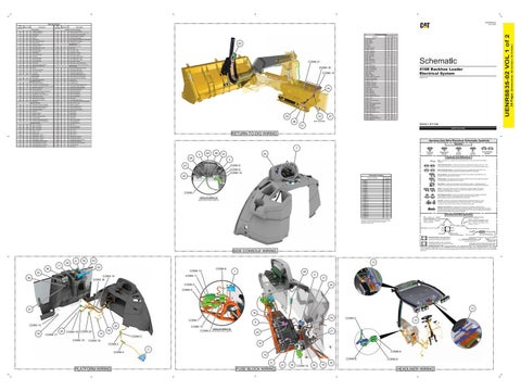
416E Backhoe Loader Electrical System LMS1573-UP
NOT SHOWN
Volume 1 of 2: Cab
51
RETURN-TO-DIG WIRING
511
BR
Radio Speaker - Right (+)
R954
OR
512
GN
Radio Speaker - Right (-)
R955
GY
Accugrade Sw Power #1 Return
513
OR
A/C Refrigerant Pressure Switch
R956
BU
Accugrade Sw Power #2
515
GY
HVAC Blower Motor #1 (High)
R957
GY
Accugrade Sw Power #2 Return
516
GN
HVAC Blower Motor #1 (Medium)
R958
GN
Accugrade Awake
517
BU
HVAC Blower Motor #1 (Low)
X977
YL
Fuel Pump (+)
Harness And Wire Electrical Schematic Symbols Symbols
7 T
40
2
36
44
53
48
Pressure Symbol
Level Symbol
Flow Symbol
A
CONN 9
Fuse: A component in an electrical circuit that will open the circuit if too much current flows through it. Switch (Normally Open): A switch that will close at a specified point (temp, press, etc.). The circle indicates that the component has screw terminals and a wire can be disconnected from it.
CONN 8 CONN 10
Switch (Normally Closed): A switch that will open at a specified point (temp, press, etc.). No circle indicates that the wire cannot be disconnected from the component. Ground (Wired): This indicates that the component is connected to a grounded wire. The grounded wire is fastened to the machine.
Connector Location
42
Connector Number CONN 1
CONN 1 VIEW OF AREA “A” (ROTATED FOR CLARITY)
Schematic Location
CONN 2
C-14 I-13
CONN 3
I-13
CONN 4 CONN 5
H-13 E-12
CONN 6
G-12
CONN 7
E-11
CONN 8
D-11
CONN 9
D-11
CONN 10
C-11
CONN 11
B-11
CONN 12
B-11
CONN 13
F-8
CONN 14
E-5
CONN 15
F-4
CONN 16
F-4
CONN 17
G-4
CONN 18
G-5
CONN 19
H-5
CONN 20
I-5
CONN 21
E-4
Ground (Case): This indicates that the component does not have a wire connected to ground. It is grounded by being fastened to the machine. Reed Switch: A switch whose contacts are controlled by a magnet. A magnet closes the contacts of a normally open reed switch; it opens the contacts of a normally closed reed switch. Sender: A component that is used with a temperature or pressure gauge. The sender measures the temperature or pressure. Its resistance changes to give an indication to the gauge of the temperature or pressure.
T
Relay (Magnetic Switch): A relay is an electrical component that is activated by electricity. It has a coil that makes an electromagnet when current flows through it. The electromagnet can open or close the switch part of the relay. Solenoid: A solenoid is an electrical component that is activated by electricity. It has a coil that makes an electromagnet when current flows through it. The electromagnet can open or close a valve or move a piece of metal that can do work. Magnetic Latch Solenoid: A magnetic latch solenoid is an electrical component that is activated by electricity and held latched by a permanent magnet. It has two coils (latch and unlatch) that make electromagnet when current flows through them. It also has an internal switch that places the latch coil circuit open at the time the coil latches.
Harness and Wire Symbols Wire, Cable, or Harness Assembly Identification: Includes Harness Identification Letters and Harness Connector Serialization Codes (see sample).
The connectors shown in this chart are for harness to harness connectors. Connectors that join a harness to a component are generally located at or near the component. See the Component Location Chart.
Harness Identification Letter(s): (A, B, C, ..., AA, AB, AC, ...)
L-C12 3E-5179
AG-C4 111-7898
L-C12 3E-5179
1
Part Number: for Connector Plug
Harness Connector Serialization Code: The "C" stands for "Connector" and the number indicates which connector in the harness (C1, C2, C3, ...).
Part Number: for Connector Receptacle
2 Plug
11
54
50
43
CONN 12
35
CONN 8
1
46
CONN 11
CONN 14 CONN 18
38
1 2
Deutsch connector: Typical representation of a Deutsch connector. The plug contains all sockets and the receptacle contains all pins.
1 2
Sure-Seal connector: Typical representation of a Sure-Seal connector. The plug and receptacle contain both pins and sockets.
Fuse (5 Amps)
5
CONN 5
24
CONN 6
B 12
37 18
CONN 13 39
26
25
45
CONN 16 CONN 20
CONN 17 CONN 15
55
CONN 9
14
CONN 5
10
6
CONN 10
VIEW OF AREA “B” (ROTATED FOR CLARITY)
21
20
CONN 3
CONN 19
16
CONN 2 CONN 4
3
CONN 8 15 CONN 6 31
PLATFORM WIRING
FUSE BLOCK WIRING
Component Part Number
Wire Gauge* Wire Color
*Wire gauge is shown in AWG (American Wire Gauge) but could also be shown in metric denoted with mm
17
CONN 7
9X-1123
325-AG135 PK-14 Harness identification code: This example indicates wire group 325, wire 135 in harness "AG".
13 52
56
5A Receptacle Pin or Socket Number
© 2020 Caterpillar. All Rights Reserved. CAT, CATERPILLAR, LET’S DO THE WORK, their respective logos, “Caterpillar Yellow,” the “Power Edge” and Cat “Modern Hex” trade dress, as well as corporate and product identity used herein, are trademarks of Caterpillar and may not be used without permission.
SIDE CONSOLE WIRING 41
Circuit Breaker Symbol
Symbols and Definitions
4
47
Temperature Symbol
23
32
CONN 19
30
19
CONN 9
22
HEADLINER WIRING
(Dimensions: 48 inches x 35 inches)
101
Wire Number
Description
36 Page,
Wire Color
UENR5835-02 VOL 1 of 2
Wire Number