Wire Number
Wire Color
101 102 105 112 113 116 118 119 121 123 124 128 143 157 161 194
RD BU BR PU OR BR GY PK YL WH GN PK BR YL PK GN
200
BK
304 306 307 308 309 310 311 321 322
WH GN OR YL GY PU WH BR GY
405 406 419 441 443 447 450
GY PU YL OR YL PK YL
SENR5811 December 1992
Wire Description Chart Description Power Distribution Circuits BAT HD LMP KEY SW MAIN POWER RELAY OUTPUT OPR MON PANEL B+ SWITCHED AUX CKT AUX CKT AUX CKT BACKUP ALARM TO LAMP AUX CKT A/C AUX CKT AUX CKT AUX CKT AUX CKT AUX CKT Ground Circuits MAIN CHASSIS Basic Machine Circuits STARTER RELAY NO. OUTPUT
Wire Number
Wire Color
500 501 502 503 504 505 506 513 515 516 517 520 521 522 536 537 538 552 564 568 576 577 A512
BR GN OR BR YL BU PU OR GY GN BU WH YL WH WH GN BR WH GY GN PK PU GN
603 604 605 606 607 608 610 611 614 617 618 619 634
PK OR YL GY PK GN OR PU PU BR YL GN WH
762 766
YL GN
STARTER RELAY COIL TO NEUT START SW OR KEY SW
KEY SW TO NEUT START SW MAIN POWER RELAY COIL ALTERNATOR REGULATOR TERM. START AID SW TO START AID SOL START AID SOL TO TEMP SW BCKP ALARM LAMP TRAVEL ALARM WARNING HORN (FORWARD) Monitoring Circuits OPR MON OIL PRESS. (LO SETTING) OPR MON COOLANT TEMP OPR MON PARKING BRAKE ENG COOLANT TEMP GAGE POWER TRAIN TEMP GAGE FUEL LEVEL GAGE TACH SENDER (+)
Description Accessory Circuits WIPER - FRONT (PARK) WIPER - FRONT (LO) WIPER - FRONT (HI) WIPER - REAR (PARK) WIPER - REAR (LO) WIPER - REAR (HI) WASHER - FRONT A/C COMPRESSOR/REFRIGERANT PRESS. SW BLOWER MOTOR (HI) BLOWER MOTOR (MEDIUM) BLOWER MOTOR (LO) OPR A/C SW TO THERMOSTAT/FUSE A/C SW TO REFRIGERANT SW A/C CLUTCH TO THERMOSTAT SW HAZARD SW TO TURN SW TURN SIGNAL SW TO FLASHER HAZARD INDICATOR FOUR WHEEL DRIVE SOL REAR WIPER INTERRUPT SW TO WIPER SW WARNING BUZZER TO DIODES WIPER - AUX (LO) WIPER - AUX (HI) REAR INTERRUPT SW TO WIPER MOTOR Lighting Circuits ROTARY BEACON STOP LAMP TURN LAMP - LEFT TURN LAMP - RIGHT FLOOD LAMP - FRONT FLOOD LAMP - REAR HEAD LAMP BASIC HEAD LAMP HI PARK/TAIL/DASH LAMP TAIL/POSITION LAMP - LEFT (ROAD PKG)/WIDTH TAIL/POSITION LAMP - RIGHT (ROAD PKG)/WIDTH HEAD LAMP LO HEAD LAMP SW TO WORK/HEAD LAMP JUMPER Control Circuits BUCKET POSITIONER SOL SW XMSN DISCONNECT SOL
Harness Connector Location Chart Connectors
Machine Location 1
12 Contacts
2
3
5
8 Contacts 6
7
6 Contacts 8
* 4 Contacts
* 9
Harness And/Or Components A - 9R9558
Part No.
Off Machine Switch Specifications
Function
8N1693
Coolant Temperature (Start Aid)
6T2665
Coolant Temperature
Actuate
37.8 ± 2.8°C (100 ± 5°F) 107.2 ± 2.8°C (225 ± 5°F)
Deactuate
Contact Position
26.7°C MIN (80°F MIN) 93°C MIN (196°F MIN)
Normally Closed Normally Closed
Resistor and Solenoid Specifications
Component
Part No.
Resistance (Ohms)¹
Resistor - Alternator
8C4110
22 ± 1.1
Resistor - Blower Motor Speed
7T3828
Overall 1.0 ± .1; Tap 0.5 ± .05
Solenoid - A/C Clutch
8T8812
3.5 ± 0.15
Solenoid - Bucket Positioner
9T7304
18
Solenoid - Start Aid
3T9493
1.5
¹ At room temperature.
416, 426, 428, 436 And 438 Series II Backhoe Loaders Electrical System 416: 5PC15429-UP
428: 6TC10381-UP
426: 7BC5259-UP
436: 5KF1553-UP
438: 3DJ2161-UP
Schematic Location B-9
K - 9R9557 E - 9R9541
B-7
H - 9R9544 E - 9R9541
E-3
L - 9R9543 B - 9R9551
A-8
E - 9R9541 D - 9R9549
B-4
E - 9R9541 E - 9R9541
A-6
G - 9R9542 D - 9R9549
C-4
E - 9R9541 A - 9R9558
D-3
Front Wiper Motor A - 9R9558 Rear Wiper Motor (Upper) HH - 9R9098
E-9
Printed in U.S.A.
1992 Caterpillar All Rights Reserved
F-7
JJ - 9R9443
* = Connector is located at the component.
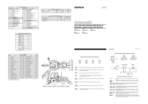
Harness And Wire Electrical Schematic Symbols Machine Location 1
Component Location Chart Component Alarm - Backup
Schematic Location B-9
Machine Location 12
Component Solenoid - Engine Shutdown
Schematic Location D-2
A
Alarm - Fault
C-3
13
Solenoid - Front Drive
C-2
2
Alternator
C-1
14
Solenoid - Start Aid
F-2
3
Batteries
F-5
15
Solenoid - Transmission Neutralizer
C-2
C
Breaker - Running Lamp
C-8
16
Switch - Backup Alarm
C-2
A
Flasher
C
Fuse - Holders
C-9
B
Switch - Beacon
D-7
C-8, C-3
A
Switch - Blower (Heater And Air Cond)
E-3
B B
Gauge - Converter Temperature
D-8
17
Switch - Bucket Positioner
A-1
Gauge - Coolant Temperature
D-8
18
Switch - Coolant Temperature
C-2
B
Gauge - Fuel
D-9
19
Switch - Coolant Temp (Start Aid)
C-1
B
Gauge - Tachometer
D-9
20
Switch - Engine Oil Pressure
D-1
4
Horn - Forward
D-1
A
Switch - Forward Horn
C-4
B
Meter - Service
D-9
B
Switch - Front Drive
C-6
B
Meter - Volt
D-8
B
Switch - Front Wiper
C-6
A
Motor - Blower
D-3
B
Switch - Hazard
D-7
A
Motor - Fan
E-7
B
Switch - Key Start
D-8
A
Motor - Front Wiper
D-3
A
Switch - Lamp Test
C-4
A
Motor - Rear Wiper (Lower)
F-8
21
Switch - Neutral/Start
C-2
A
Motor - Rear Wiper (Upper)
E-9
22
Switch - Parking Brake
F-6
5
Motor - Starter
E-2
B
Switch - Rear Dual Wiper
D-6
C
Relay
C-8
B
Switch - Rear Flood Lamp
D-7
C
Relay - Main
C-7
23
Switch - Refrigerant
F-1
C
Relay - Start
C-7
B
Switch - Running Lamp
D-6
6
Resistor - Alternator Field
D-7
B
Switch - Start Aid
D-7
A
Resistor - Blower Motor Speed
D-3
A
Switch - Thermostat
C-3
7
Sender - Converter
C-2
A
Switch - Turn Signal
E-4
8
Sender - Coolant Temperature
C-1
24
Switches - Brake (Stop Light)
D-4
9
Sender - Fuel
A-6
A
Switches - Transmission Neutralizer
10
Solenoid - Air Conditioner Clutch
D-1
A
Switches - Wiper Disconnect
11
Solenoid - Bucket Positioner
A-4
A
Typical representation of a Deutsch connector. The plug contains all sockets and the receptacle contains all pins.
Receptacle
Plug 2
Pressure Symbol
9 3 8
6
A 5
1
1
2
B
6
C
13
24 16
7
Pin or Socket Number
Flow Symbol
Wire, Cable, or Harness Assembly Identification
8
2
21
Level Symbol
4
10
7 15
20
5 12
14
Temperature Symbol
18
19
17
23
C
Normally open switch that will close with an increase of a specific condition (temp-press-etc.).
11
A
A 325-PK-14
9
Pin
AA 1
Normally closed switch that will open with an increase of a specific condition.
9 B 1
C
2
6
22
B = Components in operator compartment - Right console. 1
6 5
8 7
11
16
15
24 21
7
9 3
12
14 5
10
18
4
19
2
REED SWITCH - A switch whose contacts are controlled by a magnet. A magnet closes the contacts of a normally open reed switch; it opens the contacts of a normally closed reed switch.
23 13
No circle indicates that the wire cannot be disconnected from the component.
T
Machine Harness Connector and Component Locations
Wire Gauge
FUSE - A component in an electrical circuit that will open the circuit if too much current flows through it.
The circle indicates that the component has screw terminals and a wire can be disconnected from it.
8 20
200-BK-14
Electrical Schematic Symbols And Definitions
17
3
325-PK-14
Circuit Number Identification
Normally closed switch that is open due to an applied condition, and will close again with a specific decrease in that condition.
A
9X-1123
Wire Color
Socket
2
D-6, D-4
Component Part Number
Single Wire Connector
Normally open switch that is closed due to an applied condition, and will open again with a specific decrease in that condition.
E-8
Typical representation of a Sure-Seal connector. The plugand receptacle contain both pins and sockets.
T
3
22
1 2
1 2
1
Electrical Schematic Symbols And Definitions
A = Components in operator compartment. C = Components on relay panel (inside right console).
AA
This indicates that the component has a wire connected to it that is connected to ground.
This indicates that the component does not have a wire connected to ground. It is grounded by being fastened to the machine.
SENDER - A component that is used with a temperature or pressure gauge. The sender measures the temperature or pressure. Its resistance changes to give an indication to the gauge of the temperature or pressure. RELAY (Magnetic Switch) - A relay is an electrical component that is activated by electricity. It has a coil that makes an electromagnet when current flows through it. The electromagnet can open or close the switch part of the relay. CIRCUIT BREAKER (C/B) - A component in an electrical circuit that will open the circuit if too much current flows through it. This does not destroy the circuit breaker and it can be reset to become part of the circuit again. SOLENOID - A solenoid is an electrical component that is activated by electricity. It has a coil that makes an electromagnet when current flows through it. The electromagnet can open or close a valve or move a piece of metal that can do work. MAGNETIC LATCH SOLENOID - A magnetic latch solenoid is an electrical component that is activated by electricity and held latch by a permanent magnet. It has two coils (latch and unlatch) that make electromagnet when current flows through them. It also has an internal switch that places the latch coil circuit open at the time the coil latches.