Component Locations Components in the operator Station IDENT
Tractor Mounted Components Schematic Location F-3
Component
1
ALARM - LOW BRAKE OIL PRESSURE
2
ALARM - PARK BRAKE WARNING
3
IDENT
Operators Station
Schematic Location A-6
Component
66
AUX. START RECEPTACLE
F-2
67
BATTERI ES
A-5
BREAKER - AIR CONDITIONER
D-4
68
HORN - HIGH TONE
B-1
4
BREAKER - ALTERNATOR
D-4
69
HORN - LOW TONE
B-1
5
BREAKER - HEADLAMP
D-4
70
LAMP - CAB
6
BREAKER - KEY
E-4
71
7
BREAKER - RUNNING LAMPS
E-4
72
8
DIODE BLOCK
F-2
9
FLASHER
10
SENR8232 March 1993
29
56
24
28
32
26
33
37
39
11
34 35
25
60
Wire Number
Wire Description
Wire Color
Description
Wire Number
Wire Color
Description Monitoring Circuits
Power Circuits
31
101
RD
BATTERY
400
GN
SERVICE HOUR METER (-)
102
BU
HEAD LAMP BREAKER TO SW.
403
GN
ALTERNATOR (R) TERMINAL
103
YL
DOME/DASH/PARK/TAIL LAMP
405
GY
ENGINE OIL PRESS.
B-7
105
BR
BREAKER TO KEY SWITCH
406
PU
ENGINE COOLANT TEMP. INDICATOR
LAMP - HIGH BEAM HEAD - RIGHT
B-1
107
WH
ENGINE SHUTDOWN CONTROL
407
PK
TRANSMISSION TEMP. INDICATOR
LAMP - HIGH BEAM HEAD - LEFT
C-1
109
OR
ALTERNATOR OUTPUT (+) TERM.
419
YL
PARK BRAKE INDICATOR
73
LAMP - LOW BEAM HEAD - RIGHT
B-1
112
PU
MAIN POWER RELAY OUTPUT
432
PK
BRAKE OIL PRESSURE INDICATOR
D-2
74
LAMP - LOW BEAM HEAD - LEFT
C-1
FUSE - BACK UP ALARM
E-5
75
LAMP - TURN/PARK - RIGHT - FRONT
B-1
118
GY
FRONT WIPER FUSE TO SW.
443
YL
CONVERTER TEMP. GAUGE
11
FUSE - BODY HOIST CONTROL
E-5
76
LAMP - TURN/PARK LEFT - FRONT
C-1
121
YL
FUSE TO BACK UP ALARM SW.
449
BU
SPEEDO. PICK-UP
12
FUSE - CAB LAMP
D-5
77
MOTOR - FRONT WASHER
E-12
123
WH
FUSE TO GAUGES
450
YL
TACHOMETER PICK-UP
13
FUSE - DIFF. LOCK
D-5
78
SOLENOID - BODY RAISE
E-10
124
GN
HEATER/AIR CONDITIONER SW.
454
GN
RETARDER INDICATOR
14
FUSE - HORN
E-5
79
SOLENOID - BODY LOWER
D-10
15
FUSE - GAUGES
D-5
80
SOLENOID - PARK BRAKE
C-2
130
GN
469
GN
FUEL LEVEL SWITCH
16
FUSE - INDICATORS
D-5
81
SOLENOID - RETARDER
B-4
FUSE TO INDICATORS, LOW BRAKE OIL PRESSURE HORN AND WARNING HORN (FORWARD)
17
FUSE - PARK BRAKE
D-5
82
SOLE NIOD - START AID
C-2
158
BR
DIFF. LOCK FUSE TO SW.
477
YL
SPEEDO. PICK-UP
18
FUSE - RETARDER
E-5
83
SWITCH - BRAKE OIL PRESSURE
A-9
160
PU
BODY HOIST FUSE TO SOLENOIDS
484
YL
STEERING PRESSURE INDICATOR
19
FUSE - START AID
D-5
84
SWITCH - DISCONNECT
A-5
165
YL
FUSE TO START AID SW.
490
GN
TORQUE CON.LOCK UP INDICATOR
20
FUSE - WASH/WIPE - FRONT
E-5
85
SWITCH - FUEL LEVEL
A-2
173
YL
B404
YL
ALTERNATOR INDICATOR
21
GAUGE - CONVERTER TEMPERATURE
E-6
86
SWITCH - REFRIGERANT
B-2
190
PK
FUSE TO CAB LAMP AND STOP LAMP SWITCHES FUSE TO PARK BRAKE SW.
22
INDICATOR - ALTERNATOR CHARGE
F-4
87
SWITCH - STOP LAMP
D-3
23
INDICATOR - BRAKE OIL PRESSURE
F-5
88
SWITCH - STEERING PRESSURE
B-3
199
OR
FUSE TO RETARDER SW.
24
INDICATOR - CONVERTER LOCK
F-6
25
INDICATOR - COOLANT TEMPERATURE
F-5
IDENT
26
INDICATOR - DIFF. LOCK
F-5
89
ALTERNATOR
27
INDICATOR - ENGINE OIL PRESSURE
F-5
90
MOTOR - STARTER
A-6
28
INDICATOR - HIGH BEAM
F-5
91
PICK-UP - SPEEDOMETER
E-11
29
INDICATOR - LEFT TURN
F-6
92
PICK-UP - TACHOMETER
A-3
30
INDICATOR - LOW FUEL
F-6
93
SENDER - CONVERTER TEMP.
C-11
31
INDICATOR - PARK BRAKE
F-6
94
SOLENOID - AIR CONDTNR CLUTCH
B-3
32
INDICATOR - RETARDER
F-4
95
SOLENOID - DIFF. LOCK
B-7
33
INDICATOR - RIGHT TURN
F-4
96
SOLENOID - ENGINE SHUTDOWN
A-2
34
INDICATOR - STEERING PRESSURE
F-6
97
SWITCH - CONVERTER TEMPERATURE
F-11
35
INDICATOR - TRANSMISSION OIL TEMP
F-4
98
SWITCH - COOLANT TEMPERATURE
A-4
36
LAMP - DOME
C-7
99
37
METER - SPEEDO.
E-4
100
SWITCH - COOLANT TEMPERATURE (ETHER INHIBIT) SWITCH - ENGINE OIL PRESSURE
38
METER - SERVICE HOUR
E-5
101
SWITCH - LOCK UP PRESSURE
B-5
39
METER - TACHO
E-5
102
SWITCH - RETARDER INHIBIT
B-5
40
MOTOR - BLOWER
C-4
41
MOTOR - FRONT WIPER
C-7
IDENT
42
RELAY - ALTERNATOR CHARGE
F-1
103
ALARM-BACKUP
A-12
43
RELAY - MAIN POWER
D-4
104
LAMPS-BACKUP
A-12
44
RELAY - PARK BRAKE
E-7
105
LAMP-STOP/TAIL/TURN-RIGHT
A-12
45
RELAY - START
D-8
106
LAMP - STOP/TAIL/TURN - LEFT
B-12
46
RESISTOR - AIR CONDTNR/HEATER
D-5
47
SWITCH - BACK-UP ALARM
C-9
48
SWITCH - BLOWER
C-5
49
SWITCH - BODY HOIST CONTROL
D-8
50
SWITCH - BODY HOIST
D-8
51
SWITCH - CAB LAMP
52
SWITCH - DIFF. LOCK
53
SWITCH - DIMMER
D-2
54
SWITCH - DOME LAMP
C-7
55
SWITCH - FRONT WIPER
E-8
56
SWITCH - HORN
F-8
57
SWITCH - KEY START
E-2
58
SWITCH - NEUTRAL START
C-9
59
SWITCH - PARK BRAKE - PRESSURE
C-2
60
SWITCH - PARK BRAKE
E-8
61
SWITCH - RETARDER CONTROL
F-10
62
SWITCH - RUNNING LAMP
F-8
63
SWITCH - START AID
E-3
64
SWITCH - TURN SIGNAL
E-2
65
THERMOSTAT
C-4
62
51
55
38
21
8
12
9
63
57
27
30
23
61
50
Engine and Transmission Mounted Components Schematic Location
Component
A-3
2
48
Ground Circuits
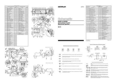
D20D & D250D Articulated Trucks Electrical System
73
75
71
77
85
67
WIPER - FRONT (PARK)
GN
WIPER - FRONT (LOW)
200
BK
MAIN CHASSIS
502
OR
WIPER - FRONT (HIGH)
200
BK
BODY HOIST CONTROL GROUND
506
PU
WASHER - FRONT
Basic Machine Circuits
513
OR
STARTER SOL. TO RESISTOR
515
GY
304
WH
STARTER RELAY TO NO.1 OUTPUT
516
GN
BLOWER MOTOR (MEDIUM)
306
GN
START RELAY TO NEUTRAL START SW.
517
BU
BLOWER MOTOR (LOW)
307
OR
KEY START SW. TO NEUTRAL START SW.
521
YL
AIR CONDITIONER SW. TO REFRIGERANT SW.
308
YL
MAIN POWER RELAY COIL
522
WH
310
PU
START AID SW. TO START AID SOL.
537
GN
AIR CONDITIONER COMPRESSOR TO THERMOSTAT SW. TURN SIGNAL SW TO FLASHER
311
WH
START AID SOL. TO TEMP SW.
539
BU
TURN SIGNAL INDICATOR - RIGHT
321
BR
BACK UP ALARM/LAMP
540
WH
TURN SIGNAL INDICATOR - LEFT
322
GY
SW. TO WARNING HORN (FORWARD)
572
PU
RETARDER INHIBIT SW. TO SOL.
324
BU
DIFF. LOCK SW. TO INDICATOR/SOL.
326
PU
KEY SWITCH "C" TERMINAL
602
WH
DOME LAMP
370
BU
604
OR
STOP LAMP SW. TO STOP LAMP
371
OR
605
YL
TURN LAMP - LEFT
606
GY
TURN LAMP - RIGHT
45
610
OR
DIMMER SW. TO RUNNING LAMP SW.
611
PU
HEAD LAMP HIGH INDICATOR
14
614
PU
PARK/TAIL/GAUGE LAMP
619
GN
HEAD LAMP - LOW
624
YL
CAB LAMP
53 49 15
52 13
20
19
4
6
6NG1-UP 9MG1-UP
5
12
1 47
10
7
Lighting Circuits
DIODE BLOCK TO LOW BRAKE OIL PRESSURE HORN DIODE BLOCK TO NEUTRAL START SW. AND PARK BRAKE WARNING HORN
3
16
Control Circuits
58 706
BR
F-7
A958
WH
TRANSMISSION RETARDER SW. TO RETARDER SOL. PARK BRAKE SOL.
B-8
B761
YL
BODY RAISE SOL.
B762
GN
BODY LOWER SOL.
43
11
18
Printed in U.S.A.
© 1993 Caterpillar All Rights Reserved
Harness And Wire Electrical Schematic Symbols
Electrical Schematic Symbols And Definitions
A
54
89
66
101
81 82
T
Pressure Symbol
Temperature Symbol
Level Symbol
Typical representation of a Deutsch connector. The plug contains all sockets and the receptacle contains all pins.
2
Flow Symbol
1 2
1 2
Receptacle
Plug
98
102
AA 1
Engine and Transmission - Right Side 40 46 65
BR
501
BU
17 Schematic Location
500
301
64
Trailer Mounted Components Component
Accessory Circuits
AIR CONDITIONER COMPRESSOR TO REFRIGERANT SW. BLOWER MOTOR (HIGH)
A-2
A-4
22
Typical representation of a Sure-Seal connector. The plugand receptacle contain both pins and sockets.
Pin or Socket Number
70
Wire, Cable, or Harness Assembly Identification
86
Single Wire Connector
Normally open switch that will close with an increase of a specific condition (temp-press-etc.). C
78
72 76
79
68 36 69
41
90
59
105
54
104
70
94
36
84
96
325-PK-14
Wire Color
Socket
200-BK-14
Circuit Number Identification
The circle indicates that the component has screw terminals and a wire can be disconnected from it.
Wire Gauge
FUSE - A component in an electrical circuit that will open the circuit if too much current flows through it. REED SWITCH - A switch whose contacts are controlled by a magnet. A magnet closes the contacts of a normally open reed switch; it opens the contacts of a normally closed reed switch.
92
No circle indicates that the wire cannot be disconnected from the component.
104 40 46 65
1
9X-1123
Electrical Schematic Symbols And Definitions Engine and Transmission - Left Side
41
AA
2
Normally closed switch that is open due to an applied condition, and will close again with a specific decrease in that condition.
103
106
Pin
Normally closed switch that will open with an increase of a specific condition.
99
80
A
A 325-PK-14
Normally open switch that is closed due to an applied condition, and will open again with a specific decrease in that condition.
74
Component Part Number
88 T
77
SENDER - A component that is used with a temperature or pressure gauge. The sender measures the temperature or pressure. Its resistance changes to give an indication to the gauge of the temperature or pressure.
This indicates that the component has a wire connected to it that is connected to ground. RELAY (Magnetic Switch) - A relay is an electrical component that is activated by electricity. It has a coil that makes an electromagnet when current flows through it. The electromagnet can open or close the switch part of the relay.
82 86
93
72
78 79
74
This indicates that the component does not have a wire connected to ground. It is grounded by being fastened to the machine.
83
100 87
91
68 69
95 97
CIRCUIT BREAKER (C/B) - A component in an electrical circuit that will open the circuit if too much current flows through it. This does not destroy the circuit breaker and it can be reset to become part of the circuit again. SOLENOID - A solenoid is an electrical component that is activated by electricity. It has a coil that makes an electromagnet when current flows through it. The electromagnet can open or close a valve or move a piece of metal that can do work. MAGNETIC LATCH SOLENOID - A magnetic latch solenoid is an electrical component that is activated by electricity and held latch by a permanent magnet. It has two coils (latch and unlatch) that make electromagnet when current flows through them. It also has an internal switch that places the latch coil circuit open at the time the coil latches.