VIEW OF AREA “A”
UENR5440-01 November 2014
REAR VIEW OF DASH
(ROTATED FOR CLARITY)
CONN 6
42
40
49 41
54
16
35
52
6
37
CONN 23
CONN 2
CONN 9
45
43
3
A
CONN 8
13
17
CONN 7
48
8 55
CONN 12 38
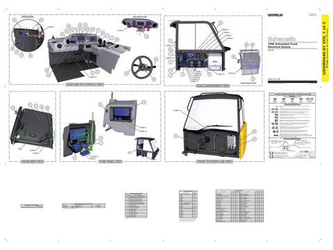
725C Articulated Truck Electrical System
29
30
LFB1-UP
9 18
5
28 50
56
CONN 13 HVAC
7
39
12
32
2
53
34
CONN 1 CONN 21 CONN 20 CONN 22 CONN 18 CONN 17
15
11 CONN 15 44
DASH AND RH CONSOLE VIEW
31
CONN 19
CONN 16 19
Volume 1 of 3: Cab
DETAIL VIEW OF “HVAC”
© 2014 Caterpillar, All Rights Reserved
Printed in U.S.A.
ECM COMPARTMENT VIEW
Harness And Wire Electrical Schematic Symbols Symbols
T
Pressure Symbol
10 51
Temperature Symbol
36
23
Flow Symbol
Circuit Breaker Symbol
Symbols and Definitions
33
47
Level Symbol
Fuse: A component in an electrical circuit that will open the circuit if too much current flows through it.
46
Switch (Normally Open): A switch that will close at a specified point (temp, press, etc.). The circle indicates that the component has screw terminals and a wire can be disconnected from it.
CONN 14
Switch (Normally Closed): A switch that will open at a specified point (temp, press, etc.). No circle indicates that the wire cannot be disconnected from the component. Ground (Wired): This indicates that the component is connected to a grounded wire. The grounded wire is fastened to the machine. Ground (Case): This indicates that the component does not have a wire connected to ground. It is grounded by being fastened to the machine. Reed Switch: A switch whose contacts are controlled by a magnet. A magnet closes the contacts of a normally open reed switch; it opens the contacts of a normally closed reed switch. Sender: A component that is used with a temperature or pressure gauge. The sender measures the temperature or pressure. Its resistance changes to give an indication to the gauge of the temperature or pressure.
T
CONN 11
Relay (Magnetic Switch): A relay is an electrical component that is activated by electricity. It has a coil that makes an electromagnet when current flows through it. The electromagnet can open or close the switch part of the relay.
CONN 10
Solenoid: A solenoid is an electrical component that is activated by electricity. It has a coil that makes an electromagnet when current flows through it. The electromagnet can open or close a valve or move a piece of metal that can do work.
20
Magnetic Latch Solenoid: A magnetic latch solenoid is an electrical component that is activated by electricity and held latched by a permanent magnet. It has two coils (latch and unlatch) that make electromagnet when current flows through them. It also has an internal switch that places the latch coil circuit open at the time the coil latches.
21 14
Harness and Wire Symbols
22 Wire, Cable, or Harness Assembly Identification: Includes Harness Identification Letters and Harness Connector Serialization Codes (see sample).
1
Harness Identification Letter(s): (A, B, C, ..., AA, AB, AC, ...)
L-C12 3E-5179
AG-C4 111-7898
1
Part Number: for Connector Plug
DOME LIGHT
L-C12 3E-5179
Harness Connector Serialization Code: The "C" stands for "Connector" and the number indicates which connector in the harness (C1, C2, C3, ...).
Part Number: for Connector Receptacle
2
CONN 3
Plug
FUSE PANEL
CONN 4
Receptacle Pin or Socket Number
1 2
Deutsch connector: Typical representation of a Deutsch connector. The plug contains all sockets and the receptacle contains all pins.
1 2
Sure-Seal connector: Typical representation of a Sure-Seal connector. The plug and receptacle contain both pins and sockets.
5A Fuse (5 Amps)
9X-1123
Component Part Number
325-AG135 PK-14
27
CONN 12 CONN 5
FUSE PANEL VIEW
HEADLINER VIEW
FRONT EXTERIOR CAB VIEW
Component Location
Connector Location Schematic Location CONN 1 - To Rear Camera G-12 CONN 2 B-11 CONN 3 I-11 CONN 4 I-11 CONN 5 G-10 CONN 6 A-9 CONN 7 D-7 CONN 8 D-7 CONN 9 - To Application ECM (ATCH) F-7 CONN 10 - Service Connection G-7 CONN 11 - ET Conncetion H-7 CONN 12 H-7 CONN 13 E-6 CONN 14 B-6 CONN 15 - To Differential Lock Switch A-6 CONN 16 B-2 CONN 17 F-1 CONN 18 F-1 CONN 19 G-1 CONN 20 H-1 CONN 21 I-1 CONN 22 J-1 CONN 23 J-1 Connector Number
Failure Mode Identifiers (FMI)¹
Resistor, Sender, and Solenoid Specifications Related Electrical Service Manuals Title Cross Reference for Electrical Connectors:
Form Number REHS0970
Part No. Component Description 167-7801 Resistor IAC Override 174-3016 Resistor CAN Data Link 2 A ¹ At room temperature unless otherwise noted.
Resistance (Ohms)¹ 390 ± 5% 120 ± 10%
FMI No. Failure Description 0 Data valid but above normal operational range. 1 Data valid but below normal operational range. 2 Data erratic, intermittent, or incorrect. 3 Voltage above normal or shorted high. 4 Voltage below normal or shorted low. 5 Current below normal or open circuit. 6 Current above normal or grounded circuit. 7 Mechanical system not responding properly. 8 Abnormal frequency, pulse width, or period. 9 Abnormal update. 10 Abnormal rate of change. 11 Failure mode not identifiable. 12 Bad device or component. 13 Out of calibration. 14 Parameter failures. 15 Parameter failures. 16 Parameter not available. 17 Module not responding. 18 Sensor supply fault. 19 Condition not met. 20 Parameter failures. ¹The FMI is a diagnostic code that indicates what type of failure has occurred.
The connectors shown in this chart are for harness to harness connectors. Connectors that join a harness to a component are generally located at or near the component. See the Component Location Chart.
Component Alarm - Action Brake Pedal AS Coil - MSS Exciter Compressor - Air Seat *NOT SHOWN Converter - 12-24V Display - CMPD ECM - Transmission ECM - VIMS Flasher AS Fuse Block AS Ground - Cab 1 Ground - Cab 2 Ground - Dash Ground - Fuse Ground Strap - Cab to Frame Instrument Cluster Lever - Shift/Hoist Quad Module - Intermittent Wiper Delay Motor - Blower Motor - Front Washer Motor - Front Wiper Motor - Rear Washer Motor - Rear Wiper MSS Key Reader Radio - Product Link Relay - Headlamp Relay - Main Resistor - CAN Data Link 2 A
Schematic Location H-10 E-10 B-11 G-10 D-1 G-11 J-4 H-7 B-7 J-9 C-3 C-2 B-11 G-7 C-3 F-11 F-10 A-6 B-4 C-4 B-4 B-4 H-14 B-6 F-4 A-6 H-9 B-7
Machine Location 1 2 3 4 5 6 7 8 9 10 11 12 13 14 15 16 17 18 19 20 21 22 23 24 25 26 27 28
Component Resistor - HVAC Resistor - IAC Override Resistor - J1939 Data Link A Sensor - Throttle Socket - 12V Power Switch - A/C Enable Switch - Axle Lock Switch - CPS Force Regen Switch - Dimmer Switch - Dome Lamp Switch - Fan Speed Switch - Hazard Switch - Head Side Lamp Switch - Heated Mirror Switch - Hood Switch - Horn Switch - Keystart Switch - LH Mirror Switch - Long Range Lamp Switch - Parking Brake Switch - Rear Wiper Switch - Retarder Switch - RH Mirror Switch - Secondary Steering Switch - Washer/Wiper/Turn Signal Switch - Work Lamp Thermostat - HVAC Valve - Water
Schematic Location B-4 D-1 E-4 F-10 G-10 E-14 E-14 J-12 D-14 B-7 E-11 D-14 C-14 F-14 F-14 A-6 A-11 I-14 J-12 E-10 D-14 A-6 I-14 E-14 B-6 C-14 B-3 C-4
Machine Location 29 30 31 32 33 34 35 36 37 38 39 40 41 42 43 44 45 46 47 48 49 50 51 52 53 54 55 56
Harness identification code: This example indicates wire group 325, wire 135 in harness "AG".
Wire Gauge Wire Color
36 Page,
25
(Dimensions: 48 inches x 35 inches)
26
UENR5440-01 VOL 1 of 3
24