37 CONN 4 39 31
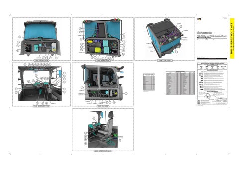
730, 730 EJ and 735 Articulated Truck Electrical System
CONN 7 28
CONN 2
38 29
730: 3T31174-UP
CONN 21
730 Ejector: 3T4135-UP
735: 3T5244-UP
15 40 10
34
13
14
CONN 5
41
12
43
CONN 3
19
CONN 1
11
CONN 12 16
CONN 10
23
46
27
36
30
9
CAB - FRONT VIEW
Volume 1 of 3: Cab
CONN 6
21
7
8
20
PUBLICATIONS.CAT.COM
CAB - REAR VIEW
CAB - TOP VIEW Harness And Wire Electrical Schematic Symbols
32
48
52
51
60
63
56
65
62
Symbols
T
Pressure Symbol
Temperature Symbol
Level Symbol
Flow Symbol
Circuit Breaker Symbol
Symbols and Definitions Fuse: A component in an electrical circuit that will open the circuit if too much current flows through it.
Component Location - Volume 1
47 Connector Location - Volume 1
24 17 67
Connector Number
55 59
18
5
61
58 53
3 50
54
Machine Location
Actuator - Water Valve
B-7
1
Schematic Location
CONN 18
1
CONN 19
Resistor - CAN 2 Term A
Schematic Location
Machine Location
G-16
35
Alarm - Action
B-10
2
Resistor - CAN 2 Term A 2
H-1
36
Block - Fuse
I-11
3
Resistor - Green Lamp
G-15
37
Blower As
B-7
4
Resistor - IAC Override
C-4
38
D-2, E-15
Coil - MSS Exciter 1
E-16
5
Resistor - Red Lamp
G-15
39
CONN 2
F-2, E-15
Compressor - Air Seat
G-12
6
Sensor - A/C Compr Discharge Press
B-7
40
CONN 3
D-15
Control - A5M4 Chassis
J-7
7
Sensor - A/C Compr Suction Press
C-7
41
CONN 4
C-15
Control - A5M4 Transmission
J-6
8
Sensor - Cab Air Temp
B-7
42
CONN 5
J-13
Control - Aftertreatment
I-3
9
Sensor - Cab Vent Air Temp
A-7
43
CONN 6
G-13
Control - Payload
F-13
10
Sensor - Evap Coil Temp
CONN 7
E-13
Control - Telematics A5N2
F-3
11
Sensor - Throttle
CONN 8
D-13
Convertor - 24V 12V (10A)
F-13
12
Sensor - Washer Fluid Level
CONN 9 - DIAGNOSTIC
G-9
Convertor - 24V 12V (15A) Seat
F-13
13
Socket - 12V Power
B-10
47
CONN 10
A-9
Diode - Door Sw Wakeup
H-9
14
Switch - Air Condr Operator
H-16
48
CONN 11
H-9
Diode - Key Sw
H-9
15
Switch - Assisted Hoist Enable
C-16
49
CONN 12
H-9
Diode - Key Sw Wakeup
G-9
16
Switch - Door
D-16
50
B-7
44
C-10
45
B-8
46
CONN 13
B-5
Display - Indication
D-10
17
Switch - DPF Regen Force
J-16
51
CONN 14
G-1, I-4
Display - Secondary
C-13
18
Switch - Economy Mode
I-16
52
CONN 15
H-1, I-4
Flasher
F-16
19
Switch - Front Work Light
E-16
53
CONN 16
H-4
Ground - ECM and Fuse
G-9
20
Switch - Hazard Light
D-16
54
CONN 17
F-4
Ground - Headliner Switch
J-13
21
Switch - Headlights
F-16
55
CONN 18
E-4
Ground - RH Console
F-16
22
Switch - Heated Mirror
I-16
56
CONN 19
D-4
Ground - Washer
B-9
23
Switch - Hood
F-16
57
CONN 20
J-2
Heated Mirror - Aux
D-15
24
Switch - Horn
B-16
58
CONN 21
E-2
Key Reader
C-16
25
Switch - Key Start
E-16
59
I-1
Lever - Shift Hoist (Ejector)
D-16
26
Switch - LH Rear View Mirror
I-16
60 61
The connectors shown in this chart are for harness to harness connectors. Connectors that join a harness to a component are generally located at or near the component. See the Component Location Chart.
49
Component
CONN 1
CONN 22
CONN 9 57
Schematic Location
Component
Motor - Front Washer
B-8
27
Switch - R ACS Platform Light
E-16
Motor - Front Wiper
C-16
28
Switch - Rear Wiper Control
G-16
62
Motor - LH Rear Wiper
G-15
29
Switch - RH Rear View Mirror
J-16
63
Motor - Rear Washer
B-8
30
Switch - Seat Belt
G-12
64
Motor - RH Rear Wiper
G-15
31
Switch - Sec Steer
H-16
65
Panel - HVAC
G-16
32
Switch - Tertiary Brake
C-16
66
Switch - Wash Wiper Turn
B-16
67
Pedal As - Brake
C-10
33
Relay - Key Sw
H-11
34
Switch (Normally Open): A switch that will close at a specified point (temp, press, etc.). The circle indicates that the component has screw terminals and a wire can be disconnected from it. Switch (Normally Closed): A switch that will open at a specified point (temp, press, etc.). No circle indicates that the wire cannot be disconnected from the component. Ground (Wired): This indicates that the component is connected to a grounded wire. The grounded wire is fastened to the machine. Ground (Case): This indicates that the component does not have a wire connected to ground. It is grounded by being fastened to the machine. Reed Switch: A switch whose contacts are controlled by a magnet. A magnet closes the contacts of a normally open reed switch; it opens the contacts of a normally closed reed switch. Sender: A component that is used with a temperature or pressure gauge. The sender measures the temperature or pressure. Its resistance changes to give an indication to the gauge of the temperature or pressure.
T
Relay (Magnetic Switch): A relay is an electrical component that is activated by electricity. It has a coil that makes an electromagnet when current flows through it. The electromagnet can open or close the switch part of the relay. Solenoid: A solenoid is an electrical component that is activated by electricity. It has a coil that makes an electromagnet when current flows through it. The electromagnet can open or close a valve or move a piece of metal that can do work. Magnetic Latch Solenoid: A magnetic latch solenoid is an electrical component that is activated by electricity and held latched by a permanent magnet. It has two coils (latch and unlatch) that make electromagnet when current flows through them. It also has an internal switch that places the latch coil circuit open at the time the coil latches.
Harness and Wire Symbols Wire, Cable, or Harness Assembly Identification: Includes Harness Identification Letters and Harness Connector Serialization Codes (see sample).
Harness Identification Letter(s): (A, B, C, ..., AA, AB, AC, ...)
L-C12 3E-5179
AG-C4 111-7898
L-C12 3E-5179
1
Part Number: for Connector Plug
Harness Connector Serialization Code: The "C" stands for "Connector" and the number indicates which connector in the harness (C1, C2, C3, ...).
Part Number: for Connector Receptacle
2 5A Plug
CONN 16 33
66
26
CONN 20
CONN 11
CONN 17
CAB - INTERIOR VIEW
CONN 13 CONN 22
42
4
44
22
2 CONN 15 CONN 14
45
64
6
CAB - OPERATOR SEAT
1 2
Deutsch connector: Typical representation of a Deutsch connector. The plug contains all sockets and the receptacle contains all pins.
1 2
Sure-Seal connector: Typical representation of a Sure-Seal connector. The plug and receptacle contain both pins and sockets.
Fuse (5 Amps)
9X-1123
Component Part Number
325-AG135 PK-14 Harness identification code: This example indicates wire group 325, wire 135 in harness "AG".
Wire Gauge* Wire Color
*Wire gauge is shown in AWG (American Wire Gauge) but could also be shown in metric denoted with mm
© 2021 Caterpillar. All Rights Reserved. CAT, CATERPILLAR, LET’S DO THE WORK, their respective logos, “Caterpillar Corporate Yellow”, the “Power Edge” and Cat “Modern Hex” trade dress as well as corporate and product identity used herein, are trademarks of Caterpillar and may not be used without permission.
CAB - RH VIEW
25
Receptacle Pin or Socket Number
(Dimensions: 56 inches x 35 inches)
35
42 Page,
CONN 8
M0116179-02 VOL 1 of 3
M0116179-02 June 2021