RENR9024-11 January 2021
26
24 89 27
37 39
19 16
93
91
28
22 A
14
32
38
90 94
E 3 20
23
F
17
25
34
43
44
15 41
31
42
33
35
92
36 40
21 29
Component Solenoid - Auxiliary Valve 5 Solenoid A Solenoid - Auxiliary Valve 5 Solenoid B Solenoid - Auxiliary Valve 6 Solenoid A Solenoid - Auxiliary Valve 6 Solenoid B Solenoid - Blade Left Lower Solenoid - Blade Left Raise Solenoid - Blade Pitch Backward Solenoid - Blade Pitch Forward Solenoid - Blade Right Lower Solenoid - Blade Right Raise Solenoid - Blade Side Shift Left Solenoid - Blade Side Shift Right Solenoid - Centershift Pin Puller Solenoid - Circle Left Solenoid - Circle Right Solenoid - Circle Side Shift Left Solenoid - Circle Side Shift Right Solenoid - Left Bladedown Force Control Solenoid - Left Bladedown Force Operation Solenoid - LH Blade Cushion Solenoid - RH Blade Cushion Solenoid - Right Bladedown Force Control Solenoid - Right Bladedown Force Operation Solenoid - Secondary Steering Left Solenoid - Secondary Steering Right Solenoid - Wheel Lean Left Solenoid - Wheel Lean Right Switch - Beacon Switch - Cab Flood Lamp Switch - Dimmer Switch - Flood Lamps Switch - Pin Puller Indicator Switch - Snow Wing Flood
Schematic Location E-6 D-6 D-6 D-6 F-4 F-4 G-4 G-4 G-4 F-4 G-4 H-4 I-4 H-4 H-4 G-4 G-4 D-3 E-3 G-3 G-3 E-3 E-3 E-4 E-4 H-4 H-4 D-12 D-12 E-12 E-12 I-4 D-12
Machine Location 31 31 32 32 32 32 31 31 32 32 31 31 38 31 31 31 31 93 93 37 37 94 94 32 32 31 31 F F F F 38 F
16M Motor Grader Electrical System B9H108-UP R9H100-349
Machine locations are repeated for components located close together. A = Located below or inside of dash. E = Located inside rear covered compartment. F = Located on right hand cab column.
Volume 1 of 3: Cab and Chassis PUBLICATIONS.CAT.COM
Harness And Wire Electrical Schematic Symbols
Connector Location - Volume 1
CONN 1
Schematic Location C-14
Machine Location E
CONN 2
D-14
E
CONN 3
E-14
E
CONN 4
G-14
E
CONN 5
D-7 , G-14
14
29
CONN 6
I-14
E
30
CONN 7
D-11
A
CONN 8
F-11
3
CONN 9
F-11
3
Connector Number 19 25
28
26 20
27
21
24 22 23
3
15
F 32
16
A 41 18
93
14
17
94 31
91 E
43
36
42 38 39 40
89
90
92
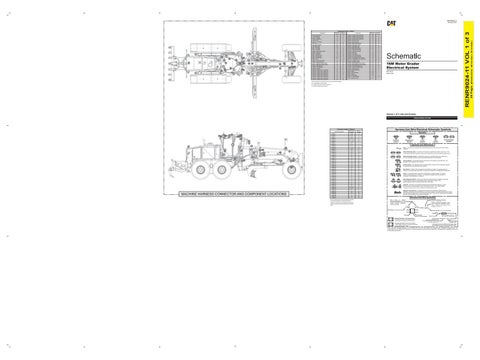
MACHINE HARNESS CONNECTOR AND COMPONENT LOCATIONS
G-10
20
E-9
21
CONN 12
E-9
21
CONN 13
E-9
22
CONN 14
E-9
21
CONN 15
E-9
22
CONN 16
F-9
23 23
44
CONN 17
F-9
35
CONN 18
F-9
25
CONN 19
F-9
26
34 33
CONN 10 CONN 11
CONN 20
F-9
24
CONN 21
F-9
24
CONN 22
F-9
22
CONN 23
F-9
27
CONN 24
G-7
14 14
CONN 25
H-7
CONN 26
E-5
93
CONN 27
F-3
92
CONN 28
F-3
35
CONN 29
F-3
39
CONN 30
F-3
40
CONN 31
F-3
42
CONN 32
G-7
A
CONN 33 CONN 34 CONN 35 CONN 36 CONN 82 CONN 83 CONN 84 CONN 85 CONN 86 CONN 87
G-3 G-3 H-2, G-2 H-2 C-11 H-3 H-3 I-3 I-3 I-3
35 35 41 41 E 44 39 35 89 43
The connectors shown in this chart are for harness to harness connectors. Connectors that join a harness to a component are generally located at or near the component. See the Component Location Chart.
Symbols
T
Pressure Symbol
Temperature Symbol
Level Symbol
Flow Symbol
Circuit Breaker Symbol
Symbols and Definitions Fuse: A component in an electrical circuit that will open the circuit if too much current flows through it. Switch (Normally Open): A switch that will close at a specified point (temp, press, etc.). The circle indicates that the component has screw terminals and a wire can be disconnected from it. Switch (Normally Closed): A switch that will open at a specified point (temp, press, etc.). No circle indicates that the wire cannot be disconnected from the component. Ground (Wired): This indicates that the component is connected to a grounded wire. The grounded wire is fastened to the machine. Ground (Case): This indicates that the component does not have a wire connected to ground. It is grounded by being fastened to the machine. Reed Switch: A switch whose contacts are controlled by a magnet. A magnet closes the contacts of a normally open reed switch; it opens the contacts of a normally closed reed switch. Sender: A component that is used with a temperature or pressure gauge. The sender measures the temperature or pressure. Its resistance changes to give an indication to the gauge of the temperature or pressure.
T
Relay (Magnetic Switch): A relay is an electrical component that is activated by electricity. It has a coil that makes an electromagnet when current flows through it. The electromagnet can open or close the switch part of the relay. Solenoid: A solenoid is an electrical component that is activated by electricity. It has a coil that makes an electromagnet when current flows through it. The electromagnet can open or close a valve or move a piece of metal that can do work. Magnetic Latch Solenoid: A magnetic latch solenoid is an electrical component that is activated by electricity and held latched by a permanent magnet. It has two coils (latch and unlatch) that make electromagnet when current flows through them. It also has an internal switch that places the latch coil circuit open at the time the coil latches.
Harness and Wire Symbols Wire, Cable, or Harness Assembly Identification: Includes Harness Identification Letters and Harness Connector Serialization Codes (see sample).
Harness Identification Letter(s): (A, B, C, ..., AA, AB, AC, ...)
L-C12 3E-5179
AG-C4 111-7898
L-C12 3E-5179
1
Part Number: for Connector Plug
Harness Connector Serialization Code: The "C" stands for "Connector" and the number indicates which connector in the harness (C1, C2, C3, ...).
Part Number: for Connector Receptacle
2 5A Plug
Receptacle Pin or Socket Number
1 2
Deutsch connector: Typical representation of a Deutsch connector. The plug contains all sockets and the receptacle contains all pins.
1 2
Sure-Seal connector: Typical representation of a Sure-Seal connector. The plug and receptacle contain both pins and sockets.
Fuse (5 Amps)
9X-1123
Component Part Number
325-AG135 PK-14 Harness identification code: This example indicates wire group 325, wire 135 in harness "AG".
Wire Gauge* Wire Color
*Wire gauge is shown in AWG (American Wire Gauge) but could also be shown in metric denoted with mm
© 2021 Caterpillar. All Rights Reserved. CAT, CATERPILLAR, LET’S DO THE WORK, their respective logos, “Caterpillar Corporate Yellow,” the “Power Edge” and Cat “Modern Hex” trade dress, as well as corporate and product identity used herein, are trademarks of Caterpillar and may not be used without permission.
(Dimensions: 48 inches x 35 inches)
30 18
Camera - Rear Vision Coil - MSS Exciter Control - Gateway Control - Implement 3 Ground - Cab 1 Ground - Front Frame 1 Horn - Air Horn - Forward (High) Key Reader - MSS LED - MSS Status Mirror - LH Heated Mirror - RH Heated Module - Steering Control Valve Monitor - Rear Vision Motor - Air Cleaner Motor - Autolube Pump Motor - LH Side Wiper Motor - RH Side Wiper Radio - Gen 2 Resistor - Steer Valve Pull-Up Sensor - Autolube Pressure Sensor - Left Steer Cylinder Position Sensor - Right Steer Cylinder Position Solenoid - Articulate Left Solenoid - Articulate Right Solenoid - Autolube Solenoid - Auxiliary Valve 1 Solenoid A Solenoid - Auxiliary Valve 1 Solenoid B Solenoid - Auxiliary Valve 2 Solenoid A Solenoid - Auxiliary Valve 2 Solenoid B Solenoid - Auxiliary Valve 3 Solenoid A Solenoid - Auxiliary Valve 3 Solenoid B Solenoid - Auxiliary Valve 4 Solenoid A Solenoid - Auxiliary Valve 4 Solenoid B
Machine Location 16 A 28 E E 14 36 35 A A 30 29 32 15 19 90 18 17 28 32 91 34 33 32 32 90 31 31 32 32 31 31 32 32
36 Page,
Component
RENR9024-11 VOL 1 of 3
Component Location - Volume 1 Schematic Location C-11 D-10 I-9 I-12 H-13 F-7 I-2 G-3 D-10 D-10 F-9 E-9 H-3 C-10 E-9 F-2 C-12 B-12 I-10 G-3 H-3 G-2 G-2 F-4 F-4 F-2 H-4 H-4 F-4 F-4 D-6 D-6 D-6 D-6