M0117586-01 May 2020
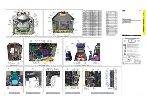
Component Location - Volume 1
16
CONN 17 83 24
14
CONN 15
84
Arc Suppressor - Rear Wiper Left Antenna - AM/FM
G-15 D-15
17 1
Bussbar
G-8
107
CONN 16
25
72
CONN 24
71
70
CONN 19
CONN 8
CONN 26
78
Control - LH Joystick
J-1
57
CONN 1
Schematic Location D-16
Control - RH Joystick
D-1
3
58
CONN 2
D-16
B-3
4
Relay - Horn
H-7
59
F-2
5
Relay - LH Position Light
G-7
60
CONN 3
D-16
CONN 4
102
CONN 18 CONN 2
CONN 21
20
CONN 5
1
21
22
CAB HEADLINER VIEW
23
54
Connector Number
55 56
6
61
CONN 4
7
Relay - Rear Wiper Motor Left
E-7
62
CONN 5
I-1
8
Relay - Rear Wiper Motor Right
F-7
63
Controller - Implement Master
E-10
9
Relay - RH Front Cab Flood
E-7
64
CONN 6
E-15
Controller - Machine
H-10
10
Relay - RH Position Lamp
F-7
65
CONN 7 - Com Converter
G-15
Controller - Steering
F-11
11
Relay - Ripper Flood
G-7
66
CONN 8
H-15
Relay - Rear Cab Lamps
Controller - Steering 2
J-11
12
Relay - Snow Wing Lamp
Converter - Communication
G-15
13
Relay - Wakeup ECM
J-2
14
D-14
F-7
G-7 G-7
67
B-15 B-15
CONN 9
68
H-15
69
CONN 10 - Service Connector
70
CONN 11
J-14
CONN 12
H-14
Resistor - CAN A 1
H-2
15
Resistor - CAN B 1
D-14
Display - D6 (Atch)
E-1
18
Resistor - GC Cab CAN
J-7
72
Display - D6 Main
F-1
19
Resistor - GC Machine CAN
J-7
73
J-15
Ground - Cab 1
B-16
20
Resistor - Steering A CAN 1
J-11
74
CONN 13
H-14
Ground - Cab 2
B-16
21
Resistor - Steering A CAN 2
C-11
75
Ground - Cab 3
B-16
22
Resistor - Steering B CAN 1
J-11
76
CONN 14
H-14
Resistor - Steering B CAN 2
C-11
77
CONN 15
G-14
Ground - Roof 1
C-16
24
Resistor - Wiper CAN 1
I-15
78
CONN 16
G-14
Ground - Roof 2 Ground - Implement Control
B-16 E-10
25 108
Resistor - Wiper CAN 2 Resistor - Ventilating Fan
I-15 E-15
79 71
CONN 17
F-14
Ground - Machine Control
I-10
109
Seat Gp
J-2
80
CONN 18
F-14
J-15
A-16
23
Keypad - Lower
C-14
26
Keypad - Middle
D-14
27
Sensor - Inching Pedal
Keypad - Upper
D-14
28
Sensor - Louver Temperature
Sensor - AWD Control Dial Position
G-2
29
Sensor - Recirculation Filter Temperature
F-15
CONN 19
F-14
82 83
CONN 20
F-14
A-15
84
CONN 21
B-14
30
Sensor - Throttle Position
F-15
31
Switch - ATC/Manual
Motor - LH Door Washer
F-15
32
Switch - Aux Lever 6
B-14
87
CONN 23 - Grade Display
J-10
H-2
33
Switch - Aux Lever 7
B-14
88
CONN 24 - Grade to Network Manager
J-10
Motor - LH Up Down Armrest
I-2
34
Switch - AWD
B-3
85
C-15
J-15
86
89
CONN 25 - Grade Audible Alarm
I-10 I-10
CONN 22
Motor - LH Window Washer
F-15
35
Switch - Brake Light
B-3
90
Motor - Rear Ventilating Fan
E-15
36
Switch - Front Wiper
I-15
92
CONN 26
F-15
37
Switch - Hazard
C-14
93
CONN 27
Motor - Rear Wiper Left
H-15
38
Switch - Heated Mirror
E-14
94
Motor - Rear Wiper Right
G-15
39
Switch - Horn
E-2
95
CONN 28
Motor - RH Door Washer
F-15
40
Switch - Implement Lockout
Motor - RH Side Wiper
H-2
41
Switch - Inching Pedal
Motor - RH Up Down Armrest
E-2
42
Switch - Key
Motor - RH Window Washer
F-15 C-15 E-14
43 44 45 46
Switch - LH Armrest
CONN 30
C-3
F-2, A-5
98
CONN 31
C-3
I-15 E-3
99 101
H-15
102
47
Switch - RH Armrest
E-2
103
I-7
48
Switch - RH Door Wiper
I-15
104
F-7
49
Switch - Seat Belt
I-7
50
Relay - Blade Flood Heel
G-7
51
Switch - Turn Signal Switch - Ventilating Fan
Relay - Blade Flood Toe
I-7
52
CAB BOTTOM VIEW
CONN 32
100
D-16 E-14
Relay - Beacon Lamp
A-3
97
Radio - Entertainment AM/FM
Relay - Blade Cushion
E-3 C-3
CONN 29
96
B-3 H-2
Switch - LH Door Wiper Switch - Park Brake Op Switch - Rear Wiper
J-10
C-14
Power Port - 12V 2 Relay - Backlighting
J-2
105
G-2 E-14
106 91
120 Motor Grader Electrical System E94215-799 E95205-799
81
B-3 A-15
Motor - LH Side Wiper
Motor - Front Wiper
Panel As - HVAC
CONN 20
I-7 H-7
H-2
Power Port - 12V 1
CONN 11
CONN 1
E-7 F-7
Relay - Headlamp Dimmer
F-2
Motor - Rear Washer
CONN 29
H-7
Relay - Grade Power Relay - Headlamp
Control Gp - LH Auxiliary
Module - Flasher
CONN 12
Relay - Grade Mast
Relay - Heated Mirror
Control Gp - LH Auxiliary
Motor - Front Washer
17
2
Control Gp - Network Manager
Ground - Cab 4
79
Connector Location - Volume 1
Control Gp - Auxiliary Pod
Converter - Voltage Entertainment Radio
CONN 27
Machine Location 53
Control Gp - Electronic
Converter - Seat
CONN 6
CONN 9
Schematic Location H-7
Component Relay - Cab Flood LH Front
C-3
CONN 33
J-2
CONN 34
A-7, F-2
The connectors shown in this chart are for harness to harness connectors. Connectors that join a harness to a component are generally located at or near the component. See the Component Location Chart.
Volume 1 of 4: Cab
Harness And Wire Electrical Schematic Symbols Symbols
15
29
38
108
109
12
39
5
19
CONN 10
T
CONN 23
Pressure Symbol
CONN 25
Temperature Symbol
Level Symbol
Flow Symbol
Circuit Breaker Symbol
Symbols and Definitions Fuse: A component in an electrical circuit that will open the circuit if too much current flows through it.
CONN 22
Switch (Normally Open): A switch that will close at a specified point (temp, press, etc.). The circle indicates that the component has screw terminals and a wire can be disconnected from it. Switch (Normally Closed): A switch that will open at a specified point (temp, press, etc.). No circle indicates that the wire cannot be disconnected from the component.
2
Ground (Wired): This indicates that the component is connected to a grounded wire. The grounded wire is fastened to the machine.
3
Ground (Case): This indicates that the component does not have a wire connected to ground. It is grounded by being fastened to the machine. Reed Switch: A switch whose contacts are controlled by a magnet. A magnet closes the contacts of a normally open reed switch; it opens the contacts of a normally closed reed switch.
8
Sender: A component that is used with a temperature or pressure gauge. The sender measures the temperature or pressure. Its resistance changes to give an indication to the gauge of the temperature or pressure.
T
Relay (Magnetic Switch): A relay is an electrical component that is activated by electricity. It has a coil that makes an electromagnet when current flows through it. The electromagnet can open or close the switch part of the relay.
74
Solenoid: A solenoid is an electrical component that is activated by electricity. It has a coil that makes an electromagnet when current flows through it. The electromagnet can open or close a valve or move a piece of metal that can do work. Magnetic Latch Solenoid: A magnetic latch solenoid is an electrical component that is activated by electricity and held latched by a permanent magnet. It has two coils (latch and unlatch) that make electromagnet when current flows through them. It also has an internal switch that places the latch coil circuit open at the time the coil latches.
Harness and Wire Symbols Wire, Cable, or Harness Assembly Identification: Includes Harness Identification Letters and Harness Connector Serialization Codes (see sample).
Harness Identification Letter(s): (A, B, C, ..., AA, AB, AC, ...)
L-C12 3E-5179
AG-C4 111-7898
L-C12 3E-5179
1
Part Number: for Connector Plug
Harness Connector Serialization Code: The "C" stands for "Connector" and the number indicates which connector in the harness (C1, C2, C3, ...).
Part Number: for Connector Receptacle
2 Plug
CONN 33 CONN 30 CONN 32 CONN 31
9
CONN 28
10
CONN 7
11
CONN 14
82
CONN 13
85
90
97
95
4
106
CAB REAR WALL VIEW
80
46
47
CONN 3
OPERATOR CONSOLE VIEW 44
86
92
94
62
104
37
35
99
34
100
43
103
45
64
41
55 63 56 61
49
51
65
A
91
66 60
67
89 68
107
28 48
57
27
101
96
98
93
81
87
53 33
32
30
73
40
CONN 34
OPERATOR LH CONSOLE VIEW
75 77
OPERATOR RH CONSOLE VIEW
54 50
88
6
OPERATOR SEAT VIEW
52
76
26 36 7
Deutsch connector: Typical representation of a Deutsch connector. The plug contains all sockets and the receptacle contains all pins.
1 2
Sure-Seal connector: Typical representation of a Sure-Seal connector. The plug and receptacle contain both pins and sockets.
Fuse (5 Amps)
9X-1123
Component Part Number
325-AG135 PK-14 Harness identification code: This example indicates wire group 325, wire 135 in harness "AG".
Wire Gauge* Wire Color
*Wire gauge is shown in AWG (American Wire Gauge) but could also be shown in metric denoted with mm
© 2020 Caterpillar. All Rights Reserved. CAT, CATERPILLAR, LET’S DO THE WORK, their respective logos, “Caterpillar Yellow,” the “Power Edge” and Cat “Modern Hex” trade dress, as well as corporate and product identity used herein, are trademarks of Caterpillar and may not be used without permission.
CAB FRONT VIEW
105
13
5A Receptacle Pin or Socket Number
1 2
OPERATOR LH PLATFORM VIEW
42 16
VIEW OF AREA “A”
59
(ROTATED FOR CLARITY)
58
OPERATOR RH PLATFORM AND FUSE BLOCK VIEW
(Dimensions: 56 inches x 35 inches)
Machine Location
I-10
Component
M0117586-01 VOL 1 of 4
Schematic Location
Arc Suppressor - Auxiliary Wakeup
42 Page,
31
18 69